Hydraulically Conductive fractures and Their Properties in Boreholes KR4 and KR7-KR10 at Olkiluoto Site
|
|
|
- Sakari Heikkilä
- 6 vuotta sitten
- Katselukertoja:
Transkriptio


1 . Working Report Hydraulically Conductive fractures and Their Properties in Boreholes KR4 and KR7-KR10 at Olkiluoto Site.. Pirjo Hella Eveliina Tammisto Henry Ahokas May 2004 POSVA OY FN OLKLUOTO, FNLAND Tel Fax
2 CONTRACTOR ORGANSATONS: JP-Fintact Oy J aakonkatu Vantaa ORDERED BY: Posiva Oy Olkiluoto NUMBER OF THE ORDERS: JP-Fintact Oy: 9546/03/AJH, 9726/03/AJH CONTACT PERSON AT POSV A: Aimo Hautojarvi Posiva Oy CONTRACTORS' CONTACT PERSONS: Henry Ahokas JP-Fintact Oy WORKNG REPORT HYDRAULCALLY CONDUCTVE FRACTURES AND THER PROPERTES N BOREHOLES KR4 AND KR7-KR10 AT OLKLUOTO STE AUTHORS: '/ 7. : Henry Ahokas JP-Fintact Oy --p,(; Pirjo Hella JP-Fintact Oy APPROVED BY Pauli Saksa JP-FintactOy
3 Working Report Hydraulically Conductive fractures and Their Properties in Boreholes KR4 and KR7-KR10 at Olkiluoto Site Pirjo Hella, Eveliina Tammisto, Henry Ahokas JP-Fintact Oy May 2004 Working Reports contain information on work in progress or pending completion. The conclusions and viewpoints presented in the report are t hose of author{s) and do not necessarily coincide with those of Posiva.
4 HelHi, P., Tammisto, E. & Ahokas, H Hydraulically conductive fractures and their properties in boreholes KR4 and KR7-KR10 at Olkiluoto site. Eurajoki: Posiva Oy. 84 p. Working Report ABSTRACT As part of the program for the final disposal of the nuclear fuel waste, Posiva Oy investigates the prevailing hydrological conditions at the Olkiluoto island. Hydraulic properties of fractures are of interest for the groundwater flow modelling and for planning of grouting and analysis of leakages etc. The detailed flow logging with 0.5 m test interval and made in 1 0 cm steps is used for exact depth determination of hydraulically conductive fractures or fracture zones. Together with borehole wall images flow logging provides possibilities to detect single conductive fractures. The results of flow logging are combined to the fracture data and other rock properties. Boreholes KR4, KR7, KR8, KR9 and KRlO have been selected as pilot holes. The conductive fractures were recognised from the images primarily based on a visible flow traces along the image. n most of the cases of measured flow, no visible flow traces were seen in the image. n these cases the most probable fracture(s) to conduct the flow were picked using the single point resistance measurements as supportive information. n order to be able to analyse the properties of the hydraulically conductive fractures, the fractures in the mineralogical/drilling report corresponding to the ones picked from the borehole wall image were identified. The combination was done based on matching the depth, intersection angle and other fracture properties (reported large aperture or thickness etc.). The results from boreholes KR7 and KR8 were checked also from the core sample. According to the results the hydraulically conductive fractures/zones could be distinguished from the borehole wall images in most cases. An important phase in the work is to calibrate the depth of the image and the flow logging with the sample length. Checking results from the core samples is essential in order to reliably correlate the borehole wall fractures to the core sample mappings. The hydraulic conductivity is clearly higher in the upper part of the bedrock in the depth range m below sea level than deeper in the bedrock. The frequency of hydraulically conductive fractures (T > m 2 /s) in depth range m varies from 1 to 3 in 1 0 m sample length. Deeper in the rock the conductive fractures are less frequent, but occur often in groups of few fractures. About 20 % of the conductive fractures are within fracture or crushed zones and another 20 % within 1 0 m distance from the zones. Single or groups of few hydraulically conductive fractures occur also on the sparsely fractured intervals. The main new information got in this study is the orientation of the conductive fractures. Keywords: Hydrology, hydraulic conductivity, transmissivity, flow logging, disposal of spent nuclear fuel
5 HelHi, P. Tammisto, E. & Ahokas, H Hydraulisesti johtavat raot ja niiden ominaisuudet kairanrei'issa KR4 and KR7-KR10. Eurajoki: Posiva Oy. 84 s. Tyoraportti TVSTELMA Osana ydinjatteen loppusijoitustutkimusta Posiva Oy selvittaa Olkiluodon saaren hydrologisia olosuhteita. Rakojen hydrauliset ominaisuudet ovat tarkeita mm. pohjavesimallinnuksessa, vuotovesien arvioinnissa, injektoinnin suunnittelussa. 0,5 m:n mittausvalein ja 0,1 m:n syvyysvalein tehdylla yksityiskohtaisella virtausmittauksella voidaan selvittaa vettajohtavoien rakojen ja rakovyohykkeiden tarkka syvyys. Yhdessa reika-tvkuvien kanssa virtausmittaus mahdollistavaa yksittaisten vettajohtavien rakojen tunnistuksen. Tassa tyossa on virtausmittauksen tulokset yhdistetty rako- ja kivilajitietoihin. Kairanreiat KR4, KR 7, KR8 KR9 ja KR1 0 on valittu esimerkkirei'iksi. Reika-tv-kuvista vettajohtavat raot tunnistettiin paaasiassa kuvassa nakyvan virtauksen avulla. Suurimmassa osassa vettajohtavista kohdista kuvasta ei voida havaita nakyvaa virtausta, jolloin kuvasta poimittiin todennakoisin vettajohtava rako hyodyntaen vastusmittaustuloksia. Vettajohtavien rakojen ominaisuuksien analysointia varten kuvasta poimitut raot yhdistettiin kairasydannaytteesta kartoitettuihin rakoihin. Yhdistaminen tehtiin syvyyden, leikkauskulman ja raon ominaisuuksien (raportoitu avoimuus/tiiveys jne.) avulla. Kairanreikien KR7 ja KR8 tulokset tarkistettiin kairasydannaytteesta. Tulosten perusteella vettajohtavat raot/vyohykkeet pystytaan yleensa tunnistamaan reika-tv-kuvista. Vettajohtavien rakojen tunnistamisen helpottamiseksi on seka reika-tvkuvan etta vedenjohtavuustulosten syvyys korjattava vastaamaan naytesyvyytta. Tulosten tarkastaminen kairasydannaytteesta auttaa kuvasta poimittujen ja naytteesta kartoitettujen rakojen yhdistelyssa ja tarkentaa tulosta. Kallion ylaosassa (0-150 m merenpinnasta) vettajohtavia rakoja esiintyy selvasti useammin kuin syvemmalla kalliossa. Kallion ylaosassa vettajohtavia rakoja (T > m 2 /s) on noin 1-3 kpl 10 m naytepituudella. Syvemmalla vettajohtavia rakoja on harvemmin, mutta ne esiintyvat usein pienina ryhmina. Noin viidesosa tunnistetuista vettajohtavista raoista sijaitsee rako- ja rikkonaisuusvyohykkeissa, suurin piirtein yhta paljon korkeintaan 10 m etaisyydelhi vyohykkeesta. Yksittaisia vettajohtavia rakoja rai niiden ryhmittymia esiintyy kuitenkin myos vahemman rakoilleessa kalliossa. Tama tyo toi ennen kaikkea uutta tietoa vettajohtavien rakojen suunnista. Avainsanat: Vedenjohtavuus, virtausmittaus, ydinjatteen loppusijoitus, hydrologia
6 1 CONTENTS Abstract Tiivistelma Preface ntroduction Background Data Recognition of the hydraulically conductive fractures Method Results Remarks on the study method Checking results from the core samples Properties of hydraulically conductive fractures Conclusions References Appendix 1 List of conductive fractures Appendix 2 Well CAD logs of conductive fractures and rock properties Appendix 3 Tables of the properties of the hydraulically conductive fractures Appendix 4 Depth calibration results... 80
7 2
8 3 PREFACE This work has been done under the contracts 9546/03/ AJH and 9726/03/ AJH by Posiva Oy. The contact person has been Aimo Hautojarvi. Henry Ahokas has guided the work done at JP-Fintact. Eveliina Tammisto has taken care of the recognition of the hydraulic fractures from the borehole wall images and compiling the required information to the Well CAD logs as well as the presentation of the results. Pirjo Hella has assisted in the gathering and checking of the input data, compiled the result tables. She has also written the report, except chapters 4.1 and 4.3 by Eveliina Tammisto, who together with Henry Ahokas has provided many valuable comments concerning also other parts of the report. All three participated also to the checking of the core samples at Loppi.

9 4
10 5 1 NTRODUCTON Posiva Oy has carried out site investigations for the disposal of spent nuclear fuel at the Olkiluoto site since late 1980's. Within the site characterisation programme, hydraulic properties of fractures are of interest for the ground water flow modelling, for planning of grouting and analysis of leakages etc. The detailed flow logging with 0.5 test interval and made in 10 cm steps provides possibilities to detect even single hydraulically conductive fractures. n this work, the results of flow logging are combined to the fracture data and other rock properties. An important data set to detect the conductive fractures has been the borehole wall images. This memorandum presents the preliminary results of the project to recognise and analyse the properties, especially orientation, of the hydraulically conductive fractures. Boreholes KR4, KR 7, KR8 (0-315 m), KR9 and KRl 0 have been selected as pilot holes. These boreholes were chosen, because they lie in the vicinity of the planned access tunnel and they give an opportunity to test the usefulness of borehole wall images made with different techniques.
11 6
12 BACKGROUND First attempts to recognise hydraulically conductive single fractures have been made in connection of the interpretation of hydraulic tests (HTU) (Kuusela-Lahtinen & Front 1991a-c). The test interval of the BTU-measurements was mostly 30 m being far too long to make it possible to get information on individual conductive fractures. More detailed analysis based on borehole-tv and difference flow loggings (2 m interval) have been made for Kivetty and Romuvaara only. The orientation of the conductive fractures in the averagely fractured rock mass outside the known fracture zones has been analysed covering boreholes KR1, KR2, KR4 and KR10 in the depth range m for technical planning purposes (see Appendix 1 in Rautakorpi et al. 2003). According to the results, there seems to be slight indications on the decrease in conductivity with steeper inclination of fractures. The conductive fractures in average rock mass are anyhow so sparse that the data set used in analysis has been very limited to make any definitive conclusions. n connection to the mapping of low temperature fracture minerals in core samples (see e.g. Gehor et al 2001) some attention has been paid also to the hydraulic conductivity. Single conductive fractures have not been recognised, but it has been concluded that on the hydraulically conductive intervals in places thicker covers of calcite and clay minerals occur than elsewhere. Sericite and quartz coatings, corroded spots and small hollows occur also on the conductive intervals. With respect to borehole KR9, Gehor et al. (1997) state that the hydraulic conductivity seems not to have exercised any distinct control over the mineral assemblages, since in most cases the zones having the best conductivity include the same minerals as those of lower conductivity. n the latest fracture mappings from the borehole wall images, the fractures with visible traces of flow have been picked (see Tammisto et al. 2003). For reference, an analogous project has been carried out within the Kamaishi URL programme in Japan (Ota & Amano 2003), in which the hydraulically conductive fractures have been identified based on the results of the standard geophysicalloggings. Conductive fracture mapping and correlation between borehole TV- and radar images and difference flow logging results concerning borehole KL02 at Laxemar in Sweden is reported by Carlsten et al. (2001). At Laxemar, the flow logging was carried out also by PRG-Tec with an identical measurement technique as in the boreholes analysed in this study. The borehole imaging technique (BPS) and the resolution are the same as used in borehole KR4 in Olkiluoto. Carlsten et al. (200 1) discuss the importance of depth adjustments in the correlation of the various results. They conclude that all the flow anomalies could be correlated with the BPS-features, either fractures or veins. Most of the flow anomalies (70-80% depending on the certainty of the correlation) are correlated to open fractures or fractures with cavities. The fracture type has been determined from the borehole wall image.
13 8
14 9 3 DATA The input data and how it is used in this work is described below: Hydraulic conductivity /transmissivi ty Difference flow logging in detailed mode measured by PRG-Tee (PolHinen & Rouhiainen 1996a, 1996b, 2001, Rouhiainen 2000). The corrections resulting from the comparison and summary of the different conductivity measurements presented by Ahokas (200 1) are taken into account. Results of electric conductivity measurements carried out in conjunction of the flow logging have been used in the depth calibration of the flow results. Fracturing The fracture data presented in the drilling reports (Jokinen 1994, Rautio 1995a, 1995b, 1996a, 1996b, 2000, Suomen Malmi 1990), resulting from the mineralogical studies by Kivitieto (Gehor et al. 1996, 1997, 2001) and fractures picked from the borehole wall images have been used. The borehole wall imaging in KR4 is done using BP-imaging technique with 1 pixel/1 o and 1 mm length resolution by Geosigma (Strahle 1996), in boreholes KR8 (0-315 m) and KR9 using OPTV technique with 1 pixel/0.5 and 0.5 mm length resolution by Robertsson Geologging (Wild et al. 2002a, 2002b) and in boreholes KR 7 and KR1 0 using OB40 technique with 1 pixel/0.5 and 0.5 mm length resolution by Astrock (Kallio et al. 2003). From boreholes KR4 (Strahle 1996, Tammisto et al. 2003) and KR9 (Tammisto et al. 2003) fracture mapping from the borehole wall image was readily available. n the other boreholes the mapping of the hydraulically conductive fractures was done within this work. Mainly fracture depth and orientation, but also fracture properties have been used to correlate the fractures detected in the different loggings (see chapter 4.1). The fracture properties in the final tables (see Appendix 1) are determined as follows although the original values are also shown: Orientation From borehole wall images, if not observed in the image the orientation according to the drilling report is used. Fracture type From the drilling reports Fracture in-fillings From mineralogical studies, if not reported in the mineralogical studies the in-fillings according to the drilling report. Only the main minerals, carbonates, sulphides, clay minerals, chlorite and graphite are taken into account, others are omitted. n addition, the fractures reported to contain hollows are marked. Shape of the fracture According to the drilling report Roughness of the fracture surface According to the drilling report
15 10 ntensity of fracturing For each of the identified conductive fracture the number of fractures on 1 meter interval (the conductive fracture in the middle) has been given. The fracture frequency has been searched from the fracture frequency results used in bedrock modelling (Vaittinen et al. 2003). The frequency is calculated from the fracture lists given in the drilling reports using the recovered sample length for each 1 m interval with 1 cm step. Rock type According to the bedrock model (Vaittinen et al. 2003), which in turn is based mainly on the mineralogical studies. Anyhow, if the fracture is clearly in another rock type as reported, the rock type is defined from the image. These situations occur because the lithology is heterogeneous and normally only the main or dominant rock type on each interval is reported although smaller intrusions of other rock type also occur. Contacts From the borehole wall images the information on whether the conductive fracture is at a lithological contact or close to contact (within few centimetres) is gathered. Foliation Picked from the image. Following definitions are used: - No foliation is present (no) - Foliation is present (yes) Foliation and the fracture are parallel Foliation and the fracture are nearly parallel Fracture is not parallel to the foliation (no) - t is not clear from the image whether the rock is foliated or not ( eos) Ri-class Defined according to drilling reports. Bedrock structures The structure type (average rock mass/hydraulic feature/fracture zone/crushed zone) in the surrounding of the fracture is defined according to the bedrock model v. 2003/1 (Vaittinen et al. 2003). Distance to the nearest fractured zone The distance along the borehole to the nearest fracture or crushed zone (as defined in the bedrock model v. 2003/1, Vaittinen et al. 2003) is also given. Table 3-1 shows the depth intervals included in the study. On these intervals both the flow logging results and borehole wall images are available.
16 r Table 3-1. The borehole intervals included in the study. KR4 KR7 KR8 KR9 KR10 tart length, m nd length, m ample length, m Depth calibration Matching the depth of the different data sets is a precondition for the recognition of the hydraulically conductive fractures and analysis of their properties. Each of the methods suffers from depth errors. The core sample is not always re-sampled correctly, for example due to the core loss or broken sections. None of the selected boreholes is drilled using the current triple tube technique, which ensures better core sample recovery. n flow logging and borehole wall imaging techniques the major source of depth error is the cable elongation, which is depth dependent. f the equipment gets stuck in the borehole stepwise depth errors are possible, but otherwise the error should be at least piecewise linear. The borehole wall image depth was checked by comparing the depths of some distinct fractures/fracture zones in the image and on the other hand in the reported core sample length. The borehole wall images were rather well calibrated to the core sample depth already as a result of previous works. n borehole KR8, the borehole wall image was approximately 0.45 m below the drilling depth constantly along the borehole. The difference flow logging depth was calibrated mainly by comparing the depth to that of the BP-image and checking that the distances between flowing points in both measurements kept constant. Depth errors were controlled by plotting the depth difference between methods as a function of depth and clear outliers of the general trend were checked separately. Depth difference between correlated fractures is presented in Appendix 5. The data was used to check the correlation. n the fracture lists in Appendix 1 the original depth for each measurement is listed, only the level adjustment of KR8 borehole wall image was done.
17 12
18 RECOGNTON OF THE HYDRAULCALLY CONDUCTVE FRACTURES 4.1 Method A Well CAD log for each borehole was compiled, presenting the flow logging results, rock types, fractures mapped from the core sample and the borehole wall images. Picking the conductive points from the flow logging results The list of flow points by PRG-Tec was readily available from boreholes KR4, KR7 and KR8. From the other boreholes, the flowing points were picked from the flow log in this study. Picking the conductive fractures from the borehole wall images The conductive fractures were recognised from the images primarily based on a visible flow along the image. n most of the cases no traces of flow was visible in the image although flow was measured at the same depth. n these cases, the most probable fracture(s) to conduct the flow were picked i.e. fractures, which are open at least partly or have a greater width. Reliability of the conductive fracture recognition from the borehole wall image was classified according to following principles: - Absolutely certain Clear signs of inflow from a fracture to the borehole in the mage or clearly distinguishable (partly) open fractures in the image. Certain Distinct fracture(s), usually at least partly open, sometimes also weak signs of flow in the image. Uncertain Fracture(s) are seen in the image, but it is difficult to distinguish a single conductive fracture either due to the large number of fractures or because only tight fractures are present, no signs of flow in the image. n some cases, although flow was measured no detectable fractures in the image existed. n few cases, clear signs of flow were visible in the image, but no flow was observed in the detailed flow measurement. n Figures 4-1, 4-2 and 4-3 examples of different situations occurring in the image are shown.


, materia/flows")
19 14 OL-KR7 Depth Lith. Fract. angle Figure 4-1. Certain observation (OL-KR7, m), materia/flows into the borehole.

 is most likely the one at 149.")
20 15 KR9 Depth '1m:3m Figure 4-2. Example of a conductive section in borehole KR9, visible upward flow can be seen from a fracture at depth m. According to difference flow measurement there are two conductive fractures at this section with cm depth difference, the lower one having a higher flow. The lower conductive fracture(s) is most likely the one at m. Here also connections between fractures can be seen.


.")
21 Depth Lith. Fract. angle 0 OL.!KR Figure 4-3. Uncertain observation (OL-KR9, m). The fracture is clear but not open. The fractures mapped from the core sample (Rautio 1996b) are shown on the left and there are no other fractures near by. Connecting the fractures to the fractures reported by core mappings n order to be able to analyse the properties of the hydraulically conductive fractures, the fractures in the mineralogical /drilling report corresponding to the ones picked from the borehole wall image were identified. The combination was done based on matching the depth, intersection angle and other fracture properties (reported large aperture or thickness etc.). ntersection angle was preferred above the exact depth matching as the angle can be determined more accurately than the depth. There are small inaccuracies in
22 17 the core sample length due to for example incomplete sample recovery. The dip direction or dip of the fracture was not used, as it is known that rather great differences in the dip direction/dip between determinations from the borehole wall image and from the oriented core sample exist. See Figure 4-4 for an example. The results of the correlation were classified into three classes: - Certain Fractures with a matching depth and intersection angle and no other as probable fractures are present. Normally the fractures are filled, but can sometimes be classified also as tight. From the images even visible flow was observed from fractures defined to be tight. - Quite certain A couple of fractures with equal properties, from which it is hard to say which one is the conductive one. - Uncertain Difference in depth or in intersection angle is big or the number of fractures is so high that it is impossible to distinguish the conductive one(s).
 -, 1- f.- 11 t- r- \ l \" \" (J lt i'\j.. 11 ::. 247.0 ()llr P r.... :.. C)lilk le r... l Figure 4-4.")

23 18 OL KR7 Depth 1m:15Ctn lnt>!!rs. llf"l9li:" nters. m e Log(K) rn:rn driling rrom mill -4 repolt boreh:lle ime J:g(T) \. 0 E( rn21!!i -4 le... lo l \ loll t r-. hf lr-lil J t:::::--. ) -, 1- f.- 11 t- r- \ l " " (J lt i'\j.. 11 :: ()llr P r.... :.. C)lilk le r... l Figure 4-4. Example on correlating flow points to fractures. On the left column all the fractures mapped from the core sample are presented, in the middle the conductive fractures picked from the borehole wall image and on the right the flow logging results. The arrows show the correlation. 4.2 Results Appendix 1 contains the list of the hydraulically conductive fractures and their properties with remarks concerning their recognition and correlation and Appendix 2 WellCAD presentations of the hydraulically conductive fractures and some other rock properties. n total 287 hydraulically conductive fractures were observed in the five boreholes, the results of boreholes KR 7 and KR8 were checked also from the core sample.
.")


24 19 Table 4-1 and Figure 4-5 summarise the results per borehole. The frequency of the hydraulically conductive fractures is calculated in two ways. All fractures having flow greater than the detection limit are encountered (see Figure 4-6 for the distribution of the transmissivity values). First, the average distance between conductive fractures is calculated simply by dividing the sample length by the number of observed conductive fractures. Secondly, the distance along borehole between two conductive fractures was calculated and the statistical parameters for the parameter calculated. Two depth intervals; from surface to 150 m below sea level (mbsl) and depths below 150 mbsl and on the other hand averagely fractured rock mass and the fractured zones were considered separately. There seems to be a clear decrease in the frequency of the conductive fractures around the depth 150 mbsl. The frequency of hydraulically conductive fractures is lowest in borehole KR4, whereas in borehole KR8 they are most frequent. This fact does not change even if the interval m in borehole KR8 is omitted to make the results better comparable with the other boreholes. n borehole KR1 0 hydraulic conductivity measurements have been done only below the depth of 100 m. The results also show that hydraulically conductive fractures appear rather evenly in the near surface part of the bedrock (1-3 conductive fractures per 10 m). Deeper the variation between boreholes is considerable, the average being 5 conductive fractures per 100 m. Deeper in the rock they are less frequent, but occur often in small groups of few conductive fractures resulting in the nearly equal median distance between fractures as in the upper part of the rock. A group of conductive features is often within or close to a fracture or crushed zone, but they occur also in less frequently fractured sections. ḡ 60 en Q) '- :::1 50 u c 40 Q) 30 Q).c Q) 20 0 c ro 10 "'0 0 KR4 KR7 KR8 KR9 KR10 Total 0 Average rock mass, z < 150 mbsl Average rock mass, z > 150 mbsl --+- Fr. zones, z > 150 mbsl - n total 6 Fr. zones, z < 150 mbsl Figure 4-5. Mean distance between hydraulically conductive fractures in the boreholes in total and at two different depth intervals in averagely fractured rock mass and in fractured zones (fracture and crushed zones as defined in the bedrock model v. 2003/1, Vaittinen et al. 2003).


25 20 Table 4-1. Summary of hydraulically conductive fractures. 11 conductive fractures KR4 KR7 KR8 KR9 KR10 Total Count Sample start length Sample end length Sample length/fracture, m m below sea level Count Sample length, m Sample length/fracture, m Distance between conductive fractures, m Average Median Stdev M in Max >150 m below sea level Count Sample length, m Sample length/fracture, m lpistance between conductive fractures, m verage Median tdev M in Max Deepest situating conductive fracture, ample length, m c :::> e log(tm2/s) Figure 4-6. Distribution of the transmissivity values. The measuring limit varies between m 2 s depending on the quality of groundwater.
26 Remarks on the study method The depth of the conductive feature in flow logging The flow loggings have been done with 10 cm depth intervals, the measured section being 0.5 m. Thus the conductive feature is somewhere within the 10 cm interval. n some cases, the conductive sections have a bit blurred edges making the depth determination difficult. The measurement of the electric conductivity provides useful substantial information as the conductive features are seen as anomalies. Cases where several over-lapping conductive intervals exist are also a bit problematic. Taking all this into account, the achievable depth accuracy is assumed to be about ± 10 cm. Picking the conductive fractures from the borehole wall image Flow can be observed in the images only when some material flows into the borehole from a fracture. Some times it is difficult to distinct if the flow actually come from the fracture or is it only remains of drilling debris on the borehole wall. Outflow cannot be seen from the images. By comparing the fracture head to the borehole head the direction of flow, either into to the borehole or out of borehole, can be determined. The fracture heads compared to the borehole pressure were checked in sections with a visible inflow in the image. n most of the cases the flow direction was indeed into the borehole, but there were some exceptions: - KR 7 at depth m (head difference 2 cm- 51 cm, see Figure 4-7) - KR8 at depths m (head difference 11 cm) and m (head difference 6 cm, see Figure 4-8) and - KRlO at depth m (head difference 43 cm) Possible reasons for the changed flow directions can be natural variation in the flow conditions. The head measurements and the image logging have been done at different times. n borehole KR 7 the flow and heads have been measured twice, before and after the extension drilling. The fracture head is normally higher compared to the borehole pressure and the inflow from fracture to borehole in the later measurement done after the extension drilling. n section m the head difference was also increased, but here the flow direction is opposite, from borehole to fracture. The head measurement using 2 m packer interval in the different runs is not done exactly at same depths and reason for differences can also be that the packer interval covers different fractures. n most cases no traces of flow was visible in the image. Often conductive points occur at a fractured zone, where detection of a single conductive fracture is difficult. n fractured zones several possibly conductive fractures were picked. These fractures were often connected to each other. Sometimes, when the flow log shows only one conductive point, there were many fractures with visible flow in the image. n some cases there were many fractures but none of them was open or partly open and no flow was visible in the image. n these cases the fracture(s) with the best matching depth was picked and reported as uncertain.


27 22 Figure 4-7. Downward flow from a fracture at depth of m in borehole OL-KR7. Another remarkable fracture at m. Comparison of the fracture and borehole head suggests that the flow is out from borehole.


.")
28 23 :KR8 Depth 1m:3m Figure 4-8. Flow from a fracture at depth of m in borehole OL-KR8 (in the image at depth m, the image depth is uncorrected). The measured fracture head is here 6 cm less than borehole head.
29 24 The accuracy of azimuth and tilt measurements from the borehole image depends on the shape of the fracture. The orientation is most accurate when the shape is smooth and the fracture intersects the borehole image perpendicularly. For stepped and undulating fractures or fractures nearly parallel to the borehole the dip direction can be difficult to define. Errors can be even several tens of degrees. The accuracy of the orientation depends also on the accuracy of the image rotation angle and of the borehole orientation, as the fracture borehole wall image is oriented according to them. Both are assumed to be within few degrees. Combining borehole wall image fractures to those mapped from the core sample The task to combine the drilling/mineralogy fractures to those observed from the borehole wall images was found to be rather difficult and time consuming. t is hard to say for example how consequently the fracture thickness has been mapped in the core sample leggings and whether the thickness is just the thickness of the in-filling or are there any signs of openness, making the correlation difficult and uncertain. This is especially true for the intervals with frequent fracturing, where there are several alternatives and even several conductive fractures. On the other hand, if the fracturing is sparse, the correlation is straightforward and reliable also. The correlation would be more reliable if a systematic fracture correspondence study were made (like the Fracture database approach, FDB, see Saksa et al and Karanko et al. 2000), giving better control on for example the depth errors. n the fracture correlations also the other fractures in the vicinity of the conductive one have to be taken into account.
30 25 5 CHECKNG RESULTS FROM THE CORE SAMPLES The fractures recognised to be hydraulically conductive in boreholes KR7 and KR8 were checked from the core sample at the national drill core depot at Loppi. The checking was done mainly to justify the correlation of image fractures and fractures reported from the core sample and also to see if any signs of flow can be detected from the core sample. The checking revealed that the correlation was done reasonably well. n many cases the conductive fractures are distinct and easily recognisable (see Figure 5-l for an example). Checking fractures from the sample helped to solve cases, where there were several alternative fractures. Also additional new conductive fractures were detected. On intervals with frequent fracturing the sample was often broken and the image is the only possible way to detect individual conductive fractures. Occasionally, the sample was taken for other studies. n Table 5-1, a summary of the checked fractures and the changes made is presented. Some observations were made during the checking: - There was often a white "collar" around the sample or white material on the fracture surface of the hydraulically conductive fractures. Often the fracture surface of the conductive fractures was smoother to touch than those of the non-conductive ones nearby, although not necessarily reported to be different in the drilling report. At some points, the conductive fracture was not through the entire sample and therefore not reported in the drilling report. At some points intersections between conductive fractures or conductive and nonconductive fractures or even termination of a fracture could be. Table 5-l. Summary of the fracture checks from the core sample at Loppi KR7 KRS Conductive fractures in total Chanoe in correlation at Loppi Fractures observed to be 8 13 conductive when checking the (5 from the older flow meter (many of the second alternatives core sample at Loppi results) were observed to be conductive, too) Removed from the conductive 0 1 fracture list Sample missing 3 10 Conductive intervals, but broken 9 7 sample so that individual fractures are not recoonisable


31 26 Figure 5-l. Two clear conductive fractures, in borehole KR 7 at sample depth m and m (the image depth is uncorrected). Checking the fractures from the core sample proved to be very useful. t is recommended that in the future, the fractures recognised to be hydraulically conductive on the base of the flow measurements and the borehole wall image are correlated to the core sample fractures when both the sample and the image are at hand. This is a much faster method and gives a more reliable result than using only the reported lists of fractures. The opportunity to check both the core sample and the borehole wall image enables to solve special situations like where a fracture is missing from the reported list or for example not through the entire sample or cases of alternative or intersecting fractures right a way. A pre-condition for the work is that the image depth is matched to the sample depth with less than 10 cm difference.


32 27 6 PROPERTES OF HYDRAULCALLY CONDUCTVE FRACTURES The summary tables of properties of the hydraulically conductive fractures are presented in Appendix 3. n the tables the results of all and on the other hand the results of the fractures classified as certain are separated in order to see if more decisive conclusions can be deduced from the certain observations. Here the certainty refers to how accurately the fractures in the borehole image are correlated to those mapped from the core sample. The correlation of fractures in boreholes KR 7 and KR8 were checked from the core sample and thus all are counted as certain. Below some remarks based on the results are given. Rock types n total about two thirds of the hydraulically conductive fractures are on migmatitic mica gneiss sections, the main rock type in the site. Roughly 30% are in granites and only a few in the less frequent rock types; tonalite, quartz feldspar gneiss and amphibolite. There are large differences between the results of different boreholes reflecting mainly the rock type variation in the near-surface part of the borehole. Less than 10 % of the hydraulically conductive fractures are located at or in the vicinity (within few centimetres) of the lithological contacts, in borehole KR1 0 none. Foliation n total, about 40% of the hydraulically conductive fractures occur on intervals with foliated rock, but the amount varies largely between boreholes. The majority of conductive fractures in foliated rock are not oriented along the foliation. Also, here the variation between boreholes is considerable. Bedrock structures About 20% of the hydraulically conductive fractures are within the fractured or crushed zones. Also this varies between boreholes - in borehole KR4 the conductive fractures are closer related to the fractured structures than in the other boreholes. The results are here a bit vague, as in the zones the single conductive fractures are difficult to distinguish and only one flow peak is seen although several fractures can be conductive. So it is likely that the number of conductive fractures within zones is actually higher. Figure 6-1 shows the distribution of the distance to the nearest fractured zone. There is a clear peak at 0 m distance, i.e. when the fracture is within the zone. The frequency within the 10 m from zone is nearly as high, but decreases then gradually. Nearly half of the conductive fractures are within the zones or 10 m distance from the zone. Fracture frequency Figure 6-2 shows the distribution of the hydraulically conductive fractures according to the number of fractures in their neighbourhood (±0.5 m distance from the fracture). The distribution is rather even i.e. single conductive fractures are nearly as frequent as conductive fractures in the zones. Here it has to be kept in mind that in the most frequently fractured sections it is likely that every single conductive fracture can't have been differentiated because of their number and the 10 cm measurement interval. t is also possible that the flow from a single fracture dominates and masks other fractures with a smaller flow in close proximity.
 distance to nearest fracture or crushed zone, m Figure 6-1.")
. The shown distance is the upper limit of the interval.")

 surrounding the conductive fracture.")

33 (.) c: (.) Q) c: :::J Q) 0"' :::J Q) g E - :::J (.) distance to nearest fracture or crushed zone, m Figure 6-1. Distribution of the distance to the nearest fractured structure (fracture or crushed zone) according to the bedrock model v. 2003/1 (Vaittinen et al. 2003). The shown distance is the upper limit of the interval = V nurrt>er of fracture/ m all certain Figure 6-2. Distribution of the hydraulically conductive fractures according to the fracture frequency on one meter interval (±0.5 m) surrounding the conductive fracture. Fracture orientation n Figure 6-3 the orientation distribution of the conductive fractures are shown on equal area lower hemisphere plots (black circles certain and white circles uncertain observations, certainty according to how reliable is the recognition of the conductive fracture from the image). Noteworthy is that in some boreholes, especially in KR7, the fracture orientations are clearly depending on the borehole orientation. Anyhow the transmissivity of the fracture is not depending on the intersection angle, see Figure 6-4.
34 29 Cerlain :-' Uncertain KR4 tqr7 R10 Figure 6-3. Orientation distribution of the hydraulically conductive fractures; stereograms of poles to the fractures shown on an equal-area, lower hemisphere projection.


35 30 (i) C\1. _ >.Q fracture/borehole intersection angle (degrees) Figure 6-4. Transmissivity of the fracture as a function of the borehole/fracture intersection angle. Fracture properties The conductive fractures are mainly defined as filled, 70 to 80% of all conductive fractures. Open fractures were mapped only in borehole KR7, where 40% of the conductive fractures were open. But in borehole KR 7 it seems that different definitions were used in core sample logging so no further conclusions are made. t is not unusual that tight fractures are also observed to be hydraulically conductive even with certainty. t is recommended that it will be checked from the borehole wall images if the fracture is open or partly open instead of using the varying fracture definitions according to the drilling report. About 20 % of the fractures have no reported infilling materials. Typical infillings are carbonates, sulphides, clay minerals, each of which are present in about % of the conductive fractures. Chlorite is also a typical infilling. There are not very great differences between the boreholes. The shape of the fracture is planar in 20% of the cases, irregular in 50% of the cases and undulating in 10% of the cases. 40% to 50% of the fractures have a semirough surface, whereas about 30% are rough and 10 % smooth. n both cases the proportions vary between boreholes.
36 31 7 CONCLUSONS This pilot study showed that it is possible to identify single hydraulically conductive fractures using the difference flow measurements (using 0.5 m test section with 0.1 m steps) and borehole wall images. Furthermore, the fractures observed from the image can be correlated with fractures observed from the core sample. The last step is tedious and most effectively done when both the image and the sample can be studied at the same time. A precondition is that the depth of flowmeter results and borehole wall images are calibrated to the sample depth with a reasonable accuracy (appr. ±10 cm). From the borehole wall image the orientation of the fracture can be interpreted and it is possible to detect the openness and shape of the fracture. Also the rock type and possible foliation can be mapped. n order to be able to analyse other properties of the hydraulically conductive fractures, like infillings, it is necessary to identify the same fractures in the core sample. Boreholes KR4, KR7, KR8 (the earlier drilled part to the depth of 315 m), KR9 and KR1 0 have been selected as pilot holes. From these boreholes all the necessary measurements were done, the borehole wall imaging with different techniques. The conductive fractures were recognised from the images primarily based on a visible flow traces along the image. Flow traces can be seen in the image, only if the flow is from the fracture to the borehole. n few cases where flow traces were observed in the image, the fracture and borehole head measurement showed that the flow direction was the opposite, from borehole to fracture. This can be due to the variation in flow conditions as the measurements have been done at different times. On most of the conductive intervals flow traces were not visible in the image and the most probable fracture(s) to conduct the flow were picked using the single point resistance measurements as supportive information. The corresponding fractures mapped from the core sample were found based on matching depth, intersection angle and other fracture properties (reported large aperture or thickness etc.). The results from boreholes KR7 and KR8 were finally checked from the core sample at the core archive. The hydraulic conductivity is clearly higher in the upper part of the bedrock in the depth range m below sea level than deeper in the bedrock. The results also show that hydraulically conductive fractures appear rather evenly in the near surface part of the bedrock. The frequency of hydraulically conductive fractures in depth range m varies from 1 to 3 in 10 m sample length. Deeper in the rock the conductive fractures are less frequent, but occur often in small groups of few fractures resulting in the nearly equal median distance between fractures as in the upper part of the rock. This can be partly due to the difficulty to differentiate each single conductive fracture in the upper parts of the rock. The main new information got in this study is the orientation of the conductive fractures. The orientation distribution in different borehole varies and is dependent on the overall borehole orientation. Dominant orientation of the fractures in the Olkiluoto boreholes is dipping gently towards southeast (see for example Anttila et al. 1999), the orientation of the hydraulically conductive fractures seems to be more diverse. Subhorizontal fractures, but with varying orientation are a clear subset, but also sub-vertical ones are present.
37 About 20 % of the conductive fractures are within fracture or crushed zones and another 20 % within 10 m distance from the zones. But single hydraulically conductive fractures occur also nearly as frequently on the sparsely fractured intervals. t is possible that on the frequently fractured sections each individual conductive fracture is not identified due to the high amount of fractures and due to the high flows which mask many less conductive fractures in close proximity. The analysis of the fracture properties of the hydraulically conductive fractures was found difficult, because of the rather varying definitions used. Most of the conductive fractures have infilling materials, carbonates, sulphates and clay minerals being present in 40% of the fractures and chlorite in 30%. The fractures are often open or partly open as can be seen from the images.
.")

38 33 REFERENCES Ahokas, H Summary of results of measurements of hydraulic conductivity and differences between different methods in boreholes KR1-KR1 0 at Olkiluoto (in Finnish with an English abstract). Helsinki, Finland: Posiva Oy. 109 p. Working report Anttila, P., Ahokas, H., Front, K., Heikkinen, E., Hinkkanen, H., Johansson, E., Paulamaki, S., Riekkola, R., Saari, J., Saksa, P., Snellman, M., Wikstrom, L., Ohberg, A Final disposal of spent nuclear fuel in Finnish bedrock - Olkiluoto site report. Helsinki, Finland: Posiva Oy. 206 p. Posiva-report Carlsten, S., Strahle, A. & Ludvigson, J.-E Conductive fracture mapping. A study on the correlation between borehole TV- and radar images and difference flow logging results in borehole KL02. Stockholm, Sweden: Svensk Kambranslehantering AB. 75 p. R Gehor, S., Karki, A., Maatta, T., Suopera, S. & Taikina-aho, Eurajoki, Olkiluoto: Petrology and low temperature fracture minerals in drill core samples (in Finnish with an English abstract). Helsinki, Finland: Posiva Oy. 300 p. Work Report PATU Gehor, S., Karki, A., Suopera, S. & Taikina-aho, Eurajoki, Olkiluoto: Petrology and low temperature fracture minerals in the OL-KR9 drill core sample (in Finnish with an English abstract). Helsinki, Finland: Posiva Oy. 56 p. Work Report Gehor, S., Karki, A., Maatta, T. & Taikina-aho, Eurajoki, Olkiluoto: Petrology and low temperature fracture minerals in drill cores OL-KR6, OL-KR7 and OL-KR12 (in Finnish with an English abstract). Helsinki, Finland: Posiva Oy. 166 p. Working Report Jokinen, J Core drilling of deep borehole OL-KR7 at Olkiluoto in Eurajoki Helsinki, Finland: Teollisuuden Voima Oy. 61 p. Working report PATU Kallio, L., Julkunen, A. & Valitalo, J Optical imaging in boreholes KR7, KR10, KR11, KR15-KR19, and KR15B-KR18B at the Olkiluoto site, Eurajoki, Finland: Posiva Oy. (in preparation) Karanko, A., Heikkinen, E. & Hella, P Supplementary fracture database from deep boreholes at Olkiluoto site (in Finnish with an English abstract). Helsinki, Finland: Posiva Oy. 362 p. Working report Kuusela-Lahtinen, A. & Front, K. 1991a. Single Borehole Hydraulic Tests in Olkiluoto, Western Finland: nterpretation of Borehole KR1 (in Finnish with an English abstract). Helsinki, Finland: Teollisuuden Voima Oy. TVO/Site investigations Work Report Kuusela-Lahtinen, A. & Front, K. 1991b. Single Borehole Hydraulic Tests in Olkiluoto, SW Finland: nterpretation of Boreholes KR2 and KR3 (in Finnish with an English abstract). Helsinki, Finland: Teollisuuden Voima Oy. TVO/Site investigations Work Report
39 34 Kuusela-Lahtinen, A. & Front, K. 1991c. Single Borehole Hydraulic Tests in Olkiluoto, SW Finland: nterpretation of Boreholes KR4 and KR5 (in Finnish with an English abstract). Helsinki, Finland: Teollisuuden Voima Oy. TVO/Site investigations Work Report Ota, K. & Amano, K Characterisation of water-conducting fractures in Crystalline rocks; Experience from Kamaishi URL programme to current Millprogramme. p. 155 in MRS 2003 Scientific basis for Nuclear Fuel Management V. Kalmar Sweden June 15-18, Abstracts. 382 p. PolHinen, J. & Rouhiainen, P. 1996a. Difference flow measurements at the Olkiluoto site in Eurajoki, boreholes KR1-KR4, KR7 and KR8. Helsinki, Finland: Posiva Oy. Working report 96-43e. Pollanen, J. & Rouhiainen, P. 1996b. Difference flow measurements at the Olkiluoto site in Eurajoki, boreholes KR9 and KR10. Helsinki, Finland: Posiva Oy. 19 p. Working report 96-44e. Pollanen, J. & Rouhiainen, P Difference flow and electric conductivity measurements at the Olkiluoto site in Eurajoki, boreholes KR6, KR7 and KR12. Helsinki, Finland: Posiva Oy. 150 p. Working Report Rautakorpi, J., Johansson, E., Tinucci, J., Palmen, J., HelHi, P., Ahokas, H. & Heikkinen, E Effect of fracturing on tunnel orientation using KB Tunnel and 3DEC programmes for the repository of spent nuclear fuel at Olkiluoto. Eurajoki, Finland:Posiva Oy. 38p. Working report Rautio, T. 1995a. Core drilling of deep borehole OL-KR8 at Olkiluoto in Eurajoki. Helsinki, Finland: Teollisuuden Voima Oy. 24 p. Working report P ATU Rautio, T. 1995b. Drilling at Olkiluoto in Eurajoki 1995, Extension of the borehole OL KR4. Helsinki, Finland: Teollisuuden Voima Oy. 20 p. Working report PATU Rautio, T. 1996a. Core drilling of deep borehole OL-KR10 at Olkiluoto in Eurajoki. Helsinki, Finland: Posiva Oy. 27 p. Working report PATU Rautio, T. 1996b. Core drilling of deep borehole OL-KR9 at Olkiluoto in Eurajoki. Helsinki, Finland: Posiva Oy. 28 p. Working report P ATU Rautio, T Extension core drilling of deep borehole OL-KR7 at Olkiluoto in Eurajoki Helsinki, Finland: Posiva Oy. 121 p. Working report Rouhiainen, P Electrical conductivity and detailed flow logging at the Olkiluoto site in Eurajoki, boreholes KR1 - KR11. Helsinki, Finland: Posiva Oy. 387 p. Working report Saksa, P., HelHi, P., Voipio, S., Nummela, J., Hanninen, T., Ahokas, H., Heikkinen, E. & Lindh, J Olkiluodon syvakallion yksityiskohtainen rakotietokanta. Helsinki, Finland: Posiva Oy. 98 p. Tyoraportti
40 35 Stnllile, A Borehole-TV measurements at the Olkiluoto site, Finland Vol. 1. Report and Appendices for OL-KRl. Vol. 2. Appendices for OL-KR2 and OL-KR4. Helsinki, Finland: Posiva Oy. 20 p + app. Work report PATU-96-59e. Suomen Malmi Oy Core drilling of deep borehole OL-KR4 at Olkiluoto in Eurajoki. Helsinki, Finland: TVO Site nvestigations. 17 p. Working report Tammisto, E., Lehtimaki, T., Palmen, J., Hella, P. & Heikkinen, E Fracture mapping from Olkiluoto borehole image data, Eurajoki, Finland: Posiva Oy. 108 p. Working Report Vaittinen, T., Ahokas, H., Heikkinen, E., Hella, P., Nummela, J., Saksa, P., Tammisto, E., Paulamaki, S., Paananen, M., Front, K. & Karki, A., Bedrock model of the Olkiluoto site, version 2003/1. Eurajoki, Finland: Posiva Oy. 266 p. Working report Wild, P., Siddans, A. & Kennaugh, K. 2002a. Optical Televiewer survey and processing in Olkiluoto site, Finland Boreholes KR9, KR12, KR13 and KR14. Helsinki, Finland: Posiva Oy. 29 p. Working report Wild, P., Siddans, A. & Wild, D. 2002b. Optical Televiewer survey and processing in boreholes KR3, KR5, KR8 and Gyro survey in borehole KR14, at the Olkiluoto site, Finland Helsinki, Finland: Posiva Oy. 86 p. Working report
41 36
42 37 APPEND 1 List of conductive fractures Hydraulically conductive fractures Borehole: Depth(m): ntersection angle (degrees 0-90) : Dip direction (degrees 0-360) : Dip (degrees 0-90): LogT(/s): T-depth(m): Flow certainty: No fractures: Ri-degree: Dist to the nearest Structure (m): Struct type: Rock type: Changed at Loppi: Loppi notes: KR, where is borehole number the depth of the drilling fracture, if not correlated the depth of the borehole wall image fracture, the depth is measured along borehole length from borehole wall images, if fracture is not observed in the image the intersection angle according to the drilling report from borehole wall images, if fracture is not observed in the image the dip direction according to the drilling report from borehole wall images, if fracture is not observed in the image the dip according to the drilling report log(t) value at T-depth the depth of a single conductive fracture detected from the flow logging results the reliability of detecting single conductive fractures from the flow logging results the number of fractures on 1 meter interval (the conductive fracture in the middle) counted from the fracture list of the drilling report refined according to drilling reports the distance along the borehole to the nearest fracture or crushed zone (as defined in the bedrock model v. 2003/1) the structure type (average rock mass/hydraulic feature/fracture zone/crushed zone) in the surrounding of the fracture is defmed according to the bedrock model v (Vaittinen et al. 2003) according to the bedrock model (Vaittinen et al. 2003), which in turn is based mainly on the mineralogical studies, if the fracture is clearly in another rock type as reported, the rock type is defined from the image x- if borehole wall image fracture or fracture correlations has been changed after checking results from the core samples Empty- if results has not been changed, boreholes KR 7 and KR8 Notes of checking fractures from the core samples, boreholes KR7 and KR8 Fractures from borehole wall image mage fracture depth(m): depth of the fracture picked from the borehole wall image, m
43 38 APPEND 1 ntersection angle (image) (degrees 0- ) : Azimuth (image) (degrees 0-360) : Tilt (image) (degrees 0-90): mage note: Contact: Foliation: Azimuth of foliation: Cert. of observation: from borehole wall image from borehole wall image from borehole wall image notes of fracture picking from the borehole wall images the information on whether the conductive fractme is at or close to a lithological contact defined from the image, following defmitions are used: -No foliation is present (no) -Foliation is present (yes) - t is not clear from the image whether the rock is foliated or not (not clear) - Foliation and the fracture are parallel (parallel to the fracture) -Foliation and the fracture are nearly parallel (rather parallel to the fracture) -Fracture is not parallel to the foliation (not parallel to the fracture) the reliability of the conductive fracture recognition from the borehole wall image before checking of the results from the core samples Fractures from core sample mapping (drilling) Drilling fracture Depth(m): ntersection angle (drilling) (degrees 0- ) : Drill note: Fracture type: Shape of the fracture surface: the depth of the correlated drilling fracture from the drilling report notes of drilling fracture correlation to borehole wall image fractures from drilling report: av- open tii- filled ti- tight avha - open slickensided tiha - tight slickensided tiiha - filled slickensided tiisa- clay filled tamu- grain filled from drilling report tasa - planar etas - irregular kaar - undulating
44 39 APPEND 1 Type of the fracture surface: Cert of drill fracture: from drilling report kark-rough pkar-semirough tasa-smooth the reliability of fracture correlation before checking of the results from the core samples Fractures from mineralogical studies Miner. fracture Depth(m): ntersection angle (miner) (degrees 0-90) : Karb: Sulphides: Clay: Corroded: Chlorite: Graphite: the depth of the correlated fracture from mineralogical report the intersection angle of the correlated fracture from mineralogical report carbonate minerals in fracture filling according to mineralogical report sulphide minerals in fracture filling according to mineralogical report clay minerals in fracture filling according to mineralogical report from mineralogical report chlorite in fracture filling according to mineralogical report graphite in fracture filling according to mineralogical report


45 OL-KR4: List of conductive fractures FT Hydrology Appendix 1 HYDRAULCALLY CONDUCTVE FRACTURES lt 116 KR t!! f ol ill J J J Mica gneiss KR Mica gneiss KR Mica gneiss KR Hydraulic feat. Mica gneiss KR Fracture zone Mica gneiss KR Fracture zone Mica gneiss KR Mica gneiss KR Mica gneiss KR Hydraulic feat. Mica gneiss KR Hydraulic feat. Mica gneiss KR Mica gneiss 0 KR KR Mica aneiss Granite KR Hydraulic feat. Mica gneiss KR Hydraulic feat. Mica gneiss KR Fracture zone Mica gneiss KR KR Fracture zone Fracture zone Mica gneiss Mica gneiss KR Mica gneiss KR Hydraulic feat. Mica gneiss KR KR KR KR uncertain Crushed zone Mica gneiss )> "U "U m z c ><... PH,ET/Fintact KR4_properties-TK-klpul.xls\Sheet1


46 OL-KR4: List of conductive fractures FT Hydrology Appendix '.! -4tl'URES FROM BOREHOLE WALL MAGE 1 i. j KR KR KR KR ! no drilling fracture not speciafically open Could this be correlated to at-value? Any of these or even all, the other possibilities include f76/26 and /205/53 ' J 11 yes yes yes yes ' FRACTURES FROM CORE SAMPLE MAPPNG (DRLLO). Jl i it 1 rather parallel quite certain to the fracture no other fractures ti etas kark quite certain rather parallel uncertain la etas pkar quite certain to the fracture parallel to the la tasa pkar quite certain fracture not parallel to certain different in FOB ll etas pkar uncertain the fracture J il! il il FRACTUERS FROM MNERALOGCAL STUDES tl 11 J SK KA cc SK cc -1 SK MO KR KR KR Either one or these, the alternative is /82154 tight fractures, unpossible to say which is conductive no clear fractures not clear certain zone, alternatively la etas kark uncertain la ha etas pkar quite certain no fractures, la etas pkar uncertain graphite, according to mineralogy rvl -1 cc MK+SK L KR no clear fractures below la tasa pkar quite certain cc SK KR KR KR KR KR KR KR downward flow open fracture open fracture with clear downward flow, also above possible fractures like / Clear open fracture Two open fractures, the one above has greater aperture, can be either one, the alternative is /125/ Clear open fracture Clear open fracture contact yes rather parallel Absolutely la etas pkar uncertain gne/gran 9 to the fracture certain cm below gne/gran yes parallel to the Absolutely parallel and ll etas pkar uncertain fracture certain similar fractures yes parallel to the fracture not clear gan/gne not yes not parallel to parallel to the fracture gran/gne 5 cm above yes not clear parallel to the fracture Absolutely or la etas pkar quite certain certain certain la etas sile uncertain certain or 301 tamu etas pkar quite certain certain parallel and la mu etas pkar quite certain similar fractures certain ti etas pkar quite certain cc SK L cc cc klor SK KA - KR KR KR KR KR KR KR R R Fracture zone, both are possible f Distinct fracture belongs to the same zone as the previous one, orientation uncertain Alternatively /208/38, the lower one is more remarkable Open fracture Fracture zone wide fracture, the orientation according to the lower edge Remarkable fracture zone Rather small fracture not clear not clear not clear yes rather parallel quite certain to the fracture or la etas pkar quite certain not clear possibly Absolutely etas pkar quite certain parallel to the certain fracture yes yes yes yes not clear not parallel to the fracture certain Amu etas kark uncertain certain ll etas kark uncertain certain ti etas pkar uncertain not clear uncertain zone la not clear/not certain or la ha etas pkar quite certain parallel to the fracture quite certain other possibilities la kaar pkar quite certain exist uncertain other possibilities la etas pkar quite certain exist cc SK+CU cc SK+CU cc SK+CU SK KA -1 cc SK sv -1 cc L L L )>., m z c 5< PH,ET/Fintact KR4_properties-TK-lopul.xls\Sheet1

47 OL-KR4: List of conductive fractures FT l-Hydrology Appendix 1 HYDRAUUCALLYCONDUFRACTURES. J t! KR J J al ill r j KR uncertain Crushed zone Quartz feldspar gneiss KR KR uncertain uncertain Crushed zone Crushed zone Pegmatite Pegmatite KR Pegmatite N )> "'0 "'0 m z c >< PH,ET F intact KR4_properties-TK-lopul.xls\Sheet1

48 OL-KR4: List of conductive fractures FT Hydrology Appendix 1 HYDRAULC FRACTURES FROM BOREHOLE WALL MAGE J! j l it t KR KR KR KR ! i t Open fractures, the lowest is the most remarkable the the upper one, the alternatives are /103/12 and Clear open fracture Clear open fracture Clear open fracture '& i : Ji ;) yes not parallel to certain the fracture yes parallel to the certain fracture [gne/qran not clear not clear certain in gran/gne yes parallel to the certain contact fracture FRACTURES FROM CORE SAMPLE MAPPNG (DRLLG) i i il il t '&!!i fl i j il! other possibilities ta tasa si le quite certain or different in FOB, tliha quite certain other 'possibility tlimu etas pkar uncertain ta etas pkar uncertain FRACTUERS FROM MNERALOGCAL STUDES lj 11 ll J SK -1 L+SV cc L KR The most probable one, other alternatives include /69/38 and not clear not parallel to quite certain the fracture other possibilities ta etas sile uncertain are and L.,J:::. V-,) )> "tj "tj m z c ><..a. PH,ET/Fintact KR4_properties-TK-opul.xls\Sheet1


49 OL-KR7: List of conductive fractures FT Hydrology Appendix 1 HYDRAUUCALL Y CONDUCTVE FRACTURES h! J V KR hi f :, ' h J J 1 ''*-' KR KR KR KR core sample broken core sample broken this and the following one very clear cases, a photo should be taken KR this and the previous one very clear casas, a photo should be taken KR KR KR KR Picked from the image after Loppi KR uncertain Crushed zone No single conductive fracture can be detected. The orientation is the according to the zone visible in the image. The depth is measured from the top and bottom point of the zone, zone is approximately 13.2 cm thick. KR KR Peamatite Pegmatite KR Pegmatite..r::....r::.. KR KR uncertain KR not measured KR Core sample is missing. KR Core sample is partly missing. KR KR Mica gneiss Mica gneiss Form the two close by fractures the lower is the conductive one. The alternative could be excluded. Core sample is missing. KR KR KR KR KR KR KR KR KR KR Crushed zone Mica gneiss Mica gneiss Mica gneiss Granite pegmatite Granite pegmatite gne Granite pegmatite Granite pegmatite Granite pegmatlte Granite pegmatite Picked from the image after Loppi (211.91). Change of the TV-fracture after Loppi, should be Changed the core sample fracture to second alternative, it might be possible that both are conductive. Fracture not through the sample, not reported in the drilling report. ntersecting the next fracture. A photo should be taken. ntersecting the previous one correlation changed at Loppi. Fracture not through the sample, not reported n the driiung report. ntersecting the next fracture. A photo should be taken. )>., m z c 5< PH,ET/FT KR7 _properties-tk_tark-lopul.xls\sheet1


50 i OL-KR7: List of conductive fractures FRACTURES FROM BOREHOLE WALL -..AGE e! i 0 tt tl ' t: j i of 1 t J 11 Jt! E! not clear yes parallel to the uncertain fracture upward and downward flow not clear certain downward flow not clear certain upward flow yes not parallel to certain the fracture FRACTURES FROM CORE SAMPLE MAPPNG (DRLUG) r lj., i. t e o j! il! ll J only possible av etas karll certain fracture av tasa pkar uncertain la etas pkar certain la etas karll quite certain la etas pkar certain FRACTUERS FROM MNERALOGCAL STUDES c:j li i i lt J SK KA cc cc cc KA FT Hydrology Appendix upward flow yes not parallel to certain the fracture la kaar pkar certain cc KA upward and downward flow yes not parallel to certain the fracture only possible av etas karll certain fracture KA downward flow no certain downward flow no certain downward flow yes parallel to the fracture open fracture downward and upward flow not clear absolutely certain downward flow, image too low no certain downward flow, image too low no certain downward flow no certain upward flow no certain upward flow no absolutely certain not open yes not parallel to uncertain the fracture ta etas karll certain only possible la etas sile certain fracture ta etas pkar quite certain zone, the depths av tasa karll uncertain are the upper and lower bounds of the zone av etas karll certain borehole image is av etas karll certain lower than other sections borehole image is av etas pkar certain lower than other sections ti etas karll certain av etas karll certain only possible la etas karll certain fracture ta etas karll certain cc KA cc cc SK ' KA cc SK KA SK KA cc SK KA KA cc SK Kl Kl Vl open fracture yes not parallel to certain the fracture clear fracture not clear certain the intersection ta etas pkar uncertain angle difference is big, but there isn't a better drilling fracture taha etas pkar quite certain cc SK L open fracture yes not parallel to certain the fracture open fracture no certain no open fracture no uncertain yes not parallel to certain the fracture open fracture not clear certain open fracture yes parallel to the certain fracture upward flow not clear certain upward flow not clear certain upward flow not clear certain clear fracture 10 cm below not clear certain could be la tasa karll quite certain av etas karll certain av etas karll quite certain tiiha kaar karll certain av etas karll certain av etas pkar certain could be av etas karll quite certain could be av etas karll quite certain ta etas karll uncertain ti etas karll uncertain av kaar pkar certain cc SK L L cc L cc SK L cc L - )> "'tj "'tj m z c >< PH,ET/FT KR7 _properties-tk_tarll-lopul.xls\sheet1


51 OL-KR7: List of conductive fractures FT Hydrology Appendix 1 J 1 t! J f KR KR '. f hi : Crushed zone Crushed zone f h Granite oeamatite broken core sample o'...' KR Crushed zone Granite pegmatite broken core sample KR Crushed zone Granite pegmatite broken core sample KR Crushed zone Granite pegmatite broken core sample KR Granite pegmatite KR KR Hydraulic feat a ne gne The alternatives could be excluded. KR KR KR Granite oeamatite gne gne This was recognised to be conductive at Loppi. KR gne 0\ KR gne This fracture is not through the core sample and thus not reported in the drilling report. KR Granite pegmatite KR KR KR KR KR Granite pegmatite a ne Granite pegmatite Granite pegmatite gne This was recognised to be conductive at Loppi. From the older flowmeter results. This was recognised to be conductive at Loppi. From the older flowmeter results. This was recognised to be conductive at Loppi. From the older flowmeter results. KR KR KR KR KR KR KR KR KR KR KR KR Hydraulic feat Fracture zone Fracture zone L...-- Granite oeamatite a ne Granite pegmatite Granite oegmatite gne Granite oeamatite Granite oeamatlte Granite oeamatite Granite oegmatite Granite j)eginatite Granite pegmatite Granite pegmatite Chanaed the core sample fracture to sacond alternative. This was recognised to be conductive at Loppi. From the older flowmeter results. Chanaed the correlated drilina fracture at Loooi. This - recognised to be conductive at Loppi based on the older flowmeter results. )> "'D "'D m z c >< PH,ETFT KR7 _properties-tk_tark-lopul.xls\sheet1


52 OL-KR7: List of conductive fractures Jl c! '& i 'lit tt t f i 11 S fl clear fracture 10cm below not clear certain possibly downward flow; not clear certain at m fracture head 2 cm less than borehole head upward and downward flow; not clear certain at fracture head 51 cm less than borehole head downward flow not clear certain clear fracture; not clear certain at fracture head fracture head 29 cm less than borehole head upward flow yes parallel to the certain fracture upward flow no certain upward flow no certain upward flow no certain upward flow yes not parallel to certain the fracture i J. ie 'C i t t il il 63 av kaar pkar zone, individual fractures not reported, no fractures a rough estimate zone, individual fractur fractures not e zone reported, no fractures a rough estimate zone, individual fractur fractures not e zone reported, no fractures a rough estimate zone, individual fractur fractures not ezone reported, no fractures a rough estimate 63 taha tasa pkar 54 ta tasa _pkar 77 only possible av etas pkar fracture 63 ti etas pkar 68 ta etas pkar 50 av etas pkar certain le si Jl cc cc cc cc certain uncertain certain uncertain certain quite certain g SK K+SV SK K+SV SK K+SV SK K+SV SK L FT Hydrology Appendix upward flow yes not parallel to certain the fracture 72 av etas pkar quite certain..j::>. -.J upward flow yes not parallel to certain the fracture upward flow yes parallel to the certain fracture no upward flow no certain no av etas kark 81 av kaar pkar 77 av etas kark 32 ta etas pkar 63 av etas pkar certain cc certain cc cc cc SK SK SK SK Kl L SV sv upward flow 2 cm below yes parallel to the certain fracture upward flow no certain open fracture no certain upward flow no certain upward flow no certain upward flow not clear certain upward flow not clear certain upward flow not clear certain upward flow not clear certain upward flow gne/ara not clear certain upward flow not clear certain no av etas pkar 54 ti etas kark 72 av etas kark 72 av etas pkar 72 av etas _pkar 72 ti tasa pkar 63 av tasa kark 36 av kaar kark 72 ti kaar kark 72 ti etas pkar 50 could be ta etas pkar 68 could be or av etas pkar ta tasa pkar... certain uncertain certain cc certain cc certain certain certain cc certain cc certain cc quite certain cc quite certain cc SK SK SK SK SK SK L L SV L )> "tj "tj m z c ><...a. PH,ET/FT KR7 _properties-tk_tark-lopul.xls\sheet1


53 OL-KR7: List of conductive fractures t j f KR hi f : Crushed zone Granite pegmatite.. h J This was recognised to be conductive at Loppi. FT Hydrology Appendix 1 KR Crushed zone Granite pegmatite KR Crushed zone Top of the zone KR Crushed zone Bottom of the zone. KR Crushed zone KR Could be, sample shows signs of flow. Recognised to be conductive at Loppi. 1 KR KR The second alternative Tv-fracture was selected at Loppi. Core fracture OK. KR Fracture zone broken sample KR KR Fracture zone Pegmatite broken sample 00 )> ""0 ""0 m z c ><..a. PH,ET/FT KR7 _properties-tk_tar11-lopul.xls\sheet1


54 OL-KR7: List of conductive fractures FT Hydrology Appendix 1 i. i ' i r &! fl c. J! ' ec: ; ' i lt t no upward flow not clear certain top depth of fracture zone not clear certain bottom depth of fracture zone not clear certain :!!.. i a G. zone, individual fractures not reported, no fractures a rough estimate zone, individual fractures not reported, no fractures a rough estimate zone, individual fractures not reported, no fractures a rough estimate in the fracture section above, no fractures estimated. ei il il 11! lt ll i cc SK 6 J i 6 Kl SV J i upward flow not clear certain zone, individual fractures not reported cc Kl open fracture yes parallel to the certain fracture open fracture, alternatively no certain /210/ open fracture, alternatively f7/83 not clear certain open fracture not clear certain open fracture no certain none fits well taha etas pkar very uncertain cc thickness 3 mm, tamu tasa karl< quite certain could also be could also be tamu etas pkar uncertain tamu kaar pkar quite certain tamu etas pkar quite certain cc SK cc SK cc SK SK L Kl Kl Kl \0 )> ""0 ""0 m z c ><...a. PH,ET/FT KR7 _properties-tk_tar1<-lopul.xls\sheet1


55 OL-KR8: List of hydraulically conductive fractures FT Hydrotogy Appendix 1 HYDRAUYCONDUcnN FRACTURE8 11 i lltl! t! 11 d Ht hi i lhl v-. 0 PH.ET/Fintact KR8_properties-TK_afk-loputxts\Sheet1
 FRACTUERS FROM MNERALOGCAL STUDES i ' tt _ t! 2034 30 19 t illlt t JJ! f b 11. 11 J 11 f J 1 '11!")
![] f_l 11 J ll i ii 6 Vosibleftow r -9cmbetow jnotclear notparallelto rsotutely 2022 23 tii kaar pkar quotecertaon 11....r :;- -; ;1!!:::---]2 :::?:::::::,;.; := :ft=-=-.... - - - --.](/docs-images/98/138997082/images/56-2.jpg "1 ' - - -:-::------'-------f-- ju:an ------- ;-- r_:_ - in _j t_j -;r-rn 1-- 2---92 90 No clear and open fracture --- yes :±--- - -----:- - pkar :::_:::_ ----- L not clear not parallel to uncertain")
56 OL-KR8: List of hydraulically conductive fractures FT Hydrology Appendix 1 FRACTURES FROM BOREHOLE WALL MAGE FRACTURES FROM CORE SAMPLE MAPPNG (DRLUO) FRACTUERS FROM MNERALOGCAL STUDES i ' tt _ t! t illlt t JJ! f b J 11 f J 1 '11! ] f_l 11 J ll i ii 6 Vosibleftow r -9cmbetow jnotclear notparallelto rsotutely tii kaar pkar quotecertaon r :;- -; ;1!!:::---]2 :::?:::::::,;.; := :ft=-= ' - - -:-::------' f-- ju:an ;-- r_:_ - in _j t_j -;r-rn No clear and open fracture --- yes :± :- - pkar :::_:::_ L not clear not parallel to uncertain loniy'possible ta etas kar1< quite certain KA :i7 5s 31' cieartracture, no- visible flow foo---- <:!.!_- quite certain a- r--eiss -Dkar- '43: ' ---- lyes neay luncertaon only reported to uncertain parahelto the fracture fohatoon Clear fracture, but no vosoble flow, fracture f; 'yes not parallel to uncertaon ta etas quite certain r o :a:'. 1 o:rds, gran/gne yes 0 :to )AhsOiutOty s ti tasa Pi<Sr- quiiecertain- "'74.60" r--l-+---l--l- - ::: 1 :,q ;;;;;;; F,-F-- :-r= =: --=- -;.;;.;;- = ,,., 0 --ltt 7579m _J_ T 3o-_ 4_7_1 21 clear fracture With flow both upwards and jy.;s--- parahel to tiie-!at>soluteiy _ ti etas kar1< - quote certiiin- 7i713 o EJ:; -:!i;,z :t:= i =3 =-==m:: f== ==r.. : ;::: --l - : -=;H H ; ; :: -H ::. ;,; ;: - :;-. - :11 :- hre m stinct open fracture/broken zone ---- notdear Absolutely tiimu tasa kar1< certain L certain ' ----T _]-- -- ;;;:ell;;_ ==-ear quite certain =- -:_,:: _ t Partly open fracture, the lowest is the most no 32 kaar pkar quite certain probable, alternatives include m and m r-;,,4 c:'==== ;:':: q:= = :--:--: M Remar1<1e open fracture, atternatively yes not parallel to jcertain Alternatively ta etas pkar uncertain /25/84 the fracture m Remar1<1e open fracture, atternatively jno!certain !Alternatively taha etas site uncertain CC SK m Vl PH,ET/Fintact KR8_properties-TK_tar1<-klpul.xls\Sheet1

ie----------------.. - -- - - --..--- ----- = - =- r :2; --:*;_ - :- :\"\"'- =!::.-:::--:- +..::;:-\"...,.;;--=--= l l,.")
57 OL-KR8: List of hydraulically conductive fractures FT Hydrology Appendix 1 lrll J J :..: r Hydraulcfeat. Granite J 1 J 1 lh sample is missing ;@thr -r 1 - J :- = 1 -- :;-= === 1 conductive. KR l Fracture zone gne sample is missing KR s 0 Fracture zone gne - x Newconducuvefractures,alsothesecondalternativesofthefollowingoneare,...,- -"''" -,-r;; --.,-- cro Ractum zone Granite tiroken sami)ie = - =- r :2; --:*;_ - :- :""'- =!::.-:::--:- +..::;:-"...,.;;--=--= l l,... '"'" " j '" ",., f ''"' ' "' --,_, "', i :::_-r:= ;! t--: t-===f: -:: =e r --:1==-===--::-:::::. =--:-=--:-_-::== KR Granite x Uncorrected image depth V N :r::-:t KR [ Fracturezone Granite Atthedepth brokenzoneinwhichatleastfourconductive fractures check these, core sample fractures and (the lower _; :, M- -r; -:=-::; -:;-t-; , ftft ft ft ftft ft ft ft ft ft Fracture zone Granite l broken sample ::: --t : :; _, ; : - :: 1- ::-l-:::: : 0 Fracturezone :: ! KROs -r T :S:s r g-f i<r08] _ :--:--=-t :F --= re s kth-1-: _: - j -} l- ----it-- -f.-:= KR ' Hydrauic feat. gne sample is missing, three possibilities with similar properties. 1 KR ' , 4.07 Granite Not conductive PH,ET/Fintact KR8_proper1ies-TK_tarl<-lopul.xls\ShMt1


58 OL-KR8: List of hydraulically conductive fractures Jl 11 tt t! Clear fracture J 1 i _J, yes 1 i 111 n 1 11 not parallel to!certain the fracture 11:::: n:::=res, \yes :;:':to jcertain t;;';;:ely t kaar kark quotecertaon -: CC j ::r-=-:+:. =:::::=t--:r- s== -:-f ---== = - F f-: ::-:=Ftt 1 the fracture !Only visible fracture, but not open yes r_ atherparalel-uncertain Alternatively tahl quotecertaon CC : SK ill' - to the fracture m! oT ss,...-t-,o - -1''Twofriiclufe5-CioseloeaCiiOther, yes p,jraiieitothe ""!Aha tasa pkar eitheronej- ---!=..yes.- a;arallel t rtain Alternatively taha t85a- pkar QUite certain of them or both, alternatively m \yes to the fracture m !paralleltotheborehole,uncertain i----ln.; quitecertain i2ooiid taha ei8ssii8"- uncertaon =l cc ----rri-tx depth and orientation. Also other fracture close by, difficult to say which is the conductive one. Alternative s m 11/81/39 j , the other. one could be j 1 ;f';!;e_=_b:::::::::7--:":::=--:=- ij-=-=: --=- --::--;:- ::-:-=::l 1 1 the fracture conductive fracture also at depth app F- :.:::=:::::::::=- =fe:- :::: -=--= = :::::: --.: :J=-=--== :i clearr;.act.;e gra/gne6cm yes ratherpiiraiieil certain PTrl ccabove to the fracture Open fracture, alternatively yes!not parallel to!absolutely Alternatively tilha tasa 1 sile uncertain CC 28/53/35!the fracture!certain m ' 32!Clear fracture, alternatively m cc SK L 29/52/26 or m 54/17/50 certaon J f everal conductive --H-fr-f l t. i:jtiiiraciiii'e ilardly-cooiductive 'bui-oio ; :;; ken ncertliin i --f--ts$8- f --i>kar -- unceilaon a+ --- f --- ===][=:==[=_=][ - -======================= =========== ======== :::::::=========== ================-===== ==============-====:= 140: other fracture close by, w not the ones r ju r:nnected to the prevoous conductove -y.- to Clear fracture, no other possobihties close by ---!Yes rather paraftel.certaon - l'"'"i40.:i t - - taha etas the fracture 52-49" Ciear fracture.-no other possoboloties close by not parallel to certaon the fracture pkar uncertain 1--:; ta kaar si le uncertain 14i l MK E;i; ::::::::f= ;:::_--.::: r oe ta tasa pkar quite certain cc L -- - t SK " li.. ;t==rr !Only possible!yes not parallel to 'uncertain only one with a ti tasa pkar certain CC SK !Open fracture, others also in the same zone, alternatives include m 29/317/3 and /289/ x- yes. ::::::to Absolutely = :-=:'----tal--,tasa :---+-S-o-.le-+-q""" ui,... te-certa --,-,- in -l-c2=50-=-.=os,--30'""+-l-+-- the fracture certain mineralogy 3 parallel fractures, the middle one l ; l o:;='iiy-:;;n p.;ssill;i;,distirlci-itiet j t r l :-63 --"--- - s r-'! A ---r---ta P<.. -,- ---;"iiecertairi -- 12s1sT :--ss-hct-- 8K cS,.,-K,... FT Hydrology Appendix 1 Vl w PH,ET/Fintact KR8_properties-TK_tark-lopul.xls\Sheet1


59 OL-KR8: List of hydraulically conductive fractures FT Hydrology Appendix 1 ll!lltl! KR KR _, 23-l ' J i<roe -r2ss r 295 -r - :;-r r =s::i J 2s5:so - -! hi , 0.78! - -s --r ois - T' J J gne Grane gne ll l New conductive fractura recognised at Loppi se-veiiiiilr&c:tlir&s iiieoiiewiiha -oenii&.iiiiiqki isiiiepiob&bie-ioiie ooiliiuctiv9: KRos -r : f.if: Fracture zooe gne 1- -sampleismissini - KRii :s:9-j 273.6o -- -! 1o '" =ti:::== """:.. =t ± ';i""'":========== Peg-matite ,, : : : KROB i Pegmatite - x New conductive fracture recognised at Loppi. Uncorrected TV :fracture depth os mu KROB gne JT. 64 :_ -L ::.?. -.J - _:-J.1_o_6_.0 KR gne ; : =:11-_ E!i ii :,;:oo:"- Ros_ _ v23-1- Pegmatite _. _Me_:stive exd _ --- _ V't PH,ET/Fintact KR8_properties-TK_tatl<-lopul.xls\Sheet1


60 OL-KRB: List of hydraulically conductive fractures FT Hydrok>gy Appendix Both fractures are open and partly overlapping, can be either one of these or both, the other alternative is m -. -? 21249!_2_7_ - 27 Vl Vl PH,ET/Fintact KR8_properties-TK_tark-lopul.lds\Sheet1

61 OL-KR9: List of hydraulically conductive fractures FT Hydrology Appendix 1 HYDRAUUCALL Y CONDUCTVE FRACTURES c 0! 1 t & c! KR f... a. r ,!! s i J J gra KR uncertain Veined gneiss KR Veined gneiss KR Veined gneiss KR KR Tonalite Tonalite KR Hydraulic feat. Tonalite KR Hydraulic feat. Tonalite KR KR KR KR uncertain Tonalite Veined gneiss Veined gneiss Veined gneiss KR Hydraulic feat. Veined gneiss KR Hydraulic feat. Veined gneiss KR KR Hydraulic feat. Veined gneiss Veined gneiss Ul 0\ KR Veined gneiss KR KR Veined gneiss Veined gneiss KR gra KR KR KR Veined aneiss Veined aneiss Veined gneiss KR Veined gneiss KR KR KR KR Veined gneiss Veined gneiss Veined gneiss Veined gneiss KR Veined gneiss KR KR KR KR KR KR KR KR Veined gneiss Veined gneiss Veined gneiss Veined gneiss Migmatic mica gneiss Migmatic mica gneiss Amphibolite )> "'tj "'tj m z c ><... PH,ET/FT KR9_properties-TK-opul.xls\Sheet1
 e J!..! ';i 'C ft 11,!ll J 0 e c. li ';i! il c: i 41.")

62 OL-KR9: List of hydraulically conductive fractures FT Hydrology Appendix 1.. H i FRACTURES FROM BOREHOLE WALL MAGE ft i. E ; c E only possible fracture r 8 jj ';i :1 8 :. 11 not clear '; certain FRACTURES FROM CORE SAMPLE MAPPNG (DRLLG) e J!..! ';i 'C ft 11,!ll J 0 e c. li ';i! il c: i too big intersection la etas pkar uncertain angle difference FRACTUERS FROM MNERALOGCAL! STUDES u :! lt 1 l! t.!.6: A ll' :sr l u fi cc SK only possible fracture clear fracture not clear clear fracture only possible fracture clear fracture clear fracture fracture zone fracture zone fracture zone clear fracture yes not parallel to uncertain the fracture yes not parallel to certain the fracture gran/gne yes not parallel to uncertain the fracture not clear certain yes parallel to the uncertain fracture yes not parallel to certain the fracture yes not clear not clear not clear not clear not parallel to certain the fracture certain certain certain certain only possible ti etas kark quite certain ti etas kark certain ti etas kark quite certain la etas kark certain la etas pkar certain too big intersection ti kaar kark uncertain angle difference ta etas kark certain la kaar kark uncertain la kaar kark certain la kaar kark uncertain could also be ti etas uncertain 69.34, ti etas kark certain kiis cc KA cc SK cc cc cc KA cc L cc L kiis clear fracture very unclear fracture uncertain, alternatively m 66/183/45 yes parallel to the certain fracture yes parallel to the uncertain fracture no uncertain la tasa sile certain ta tasa kark uncertain Alternatively la etas kark certain SK SK SM cc SK SM Vl -J Alternatively la etas kark uncertain cc SK SM only possible fracture not clear not open no fractures no fractures fracture in the same fracture zone not clear open fracture only possible fracture not clear certain yes not parallel to uncertain the fracture yes not parallel to uncertain the fracture yes not parallel to certain the fracture no no no uncertain certain quite certain ti tasa pkar certain la etas pkar uncertain ta etas kark certain Alternatively 78.7 ti etas pkar quite certain ti etas kark quite certain taha tasa sile uncertain only possible ti etas pkar quite certain ahough tight la etas pkar uncertain from mineralogy quite certain la etas kark certain la tasa pkar certain KA cc KA cc cc cc cc kiis KA possibly this fracture possibly this fracture both are possible, alternative is /170n8 clear fracture no fractures clear fracture yes not parallel to uncertain the fracture not clear uncertain no certain yes not parallel to certain the fracture gne/amf yes not parallel to certain the fracture la etas pkar certain la etas kark certain ahematively la tasa pkar certain ti etas kark certain weathered ti tasa pkar quite certain according to mineralogy alternatively taha tasa si le uncertain only possible ti kaar kark uncertain syiipynyt ti kaar!quite certain tii tasa pkar certain cc SK cc cc SK KA cc KA cc SK SM+KA )> ""0 ""0 m z c >< PH,ET/FT KR9_properties-TK-opul.xls\Sheet1


63 OL-KR9: List of hydraulically conductive fractures FT Hydrology Appendix 1 i t, KR J J f! 4 hi J J Veined gneiss KR uncertain Veined gneiss 'KR Veined gneiss KR Veined gneiss KR Veined gneiss KR Crushed zone Veined gneiss KR Crushed zone Veined gneiss KR Crushed zone Veined gneiss KR Crushed zone Veined gneiss KR KR Peamatite_granite Pegmatite granite KR KR KR KR KR KR KR uncertain Pegmatite granite Pegmatite granite Mica gneiss Quartzite gneiss Quartzite gneiss Quartzite gneiss Quartzite gneiss Vl 00 KR KR Quartzite ijneiss Quartzite gneiss KR Veined gneiss KR Pegmatite granite KR Fracture zone Veined gneiss KR Fracture zone Veined gneiss KR uncertain 15 0 Fracture zone Veined gneiss KR KR KR KR KR KR KR uncertain Fracture zone 0 Fracture zone Fracture zone 1.05 Veined gneiss Veined gneiss Veined gneiss Veined gneiss Veined gneiss )> "'D "'D m z c ><..a. PH,ET/FT KR9_properties-TK-opul.xls\Sheet1


64 i OL-KR9: List of hydraulically conductive fractures '! it i :si. E J c. J clear fracture clear fracture E both are possible, not open, alternative is m 45/263/42 open fracture clear fracture open fracture in fracture zone c 0 jl of S ft 8 :. j yes not parallel to certain the fracture yes not parallel to certain the fracture yes not parallel to uncertain the fracture yes parallel to the certain fracture yes not parallel to uncertain the fracture no certain jl! Ji -! i Ji Jl 01 c r! 54 ti tasa pkar 32 ta etas kark 50 Atternatively ti etas kark m 59 tamu tasa kark 41 ta tasa pkar 54 ta etas pkar a le n si li certain certain quite certain uncertain certain certain s i cc cc cc SK SK,.. a i 8 t5 FT Hydrology Appendix 1 J open fracture in fracture zone no certain could be ta etas pkar quite certain SK open fracture in fracture zone not clear certain ti kaar kark uncertain look , maybe one of them upward flow from the fracture upward and downward flow from the fracture no certain no certain several tamu tamu etas pkar fractures 32 ta etas sile 50 this is a conductive ti tasa pkar fracture, but difficutt to correlate tot-value uncertain certain certain SK L L downward flow from the fracture open fracture open fracture open fracture no fractures clear fracture upward and downward flow from the fracture no certain no certain no certain not clear certain not clear certain not clear certain tamu tasa pkar 50 ti tasa kark 63 ti tasa kark 54 ta etas kark 36 ta etas sile 27 ta kaar kark 27 Atternatively taha kaar sile ta etas sile 72 Atternatively ti tasa kark the depth matches ti tasa better to but intersection angle don't certain certain uncertain [quite certain uncertain quite certain quite certain certain uncertain uncertain cc cc cc SK SK L L KA SM+PA L L L Vl \ g no fractures open fracture open fracture open fracture, alternatives /212/19 and /151/36 open fracture open fracture can't say which one of the fractures not clear not open alternatively /1 02/ no certain no certain not clear certain no certain no certain yes parallel to the uncertain fracture no uncertain no uncertain the upper ti etas kark alternative is closed,alternatively m 77 tamu etas kark 77 ta etas pkar 72 Attematives ta etas pkar include and ti tasa pkar 45 ta etas pkar 54 ta etas kark 81 ta etas pkar 18 taha etas sile 45 taha etas pkar 81 too many drilling ta tasa pkar fractures quite certain certain certain certain certain uncertain quite certain uncertain uncertain quite certain uncertain cc cc cc cc cc cc SK SK SK SK SK )> "'tj "'tj m z c >< PH,ETFT KR9_properties-TK-opul.xls\Sheet1

65 OL-KR10: List of hydraulically conductive fractures FT Hydrology Appendix 1. j J cl KR r S i!e! lt!i ! KR KR KR KR KR KR KR KR Granite oeamatite Granite pegmatite Granite pegmatite Migmatltlc mica gneiss KR KR KR KR KR KR KR KR uncertain uncertain gra gne gne Granite pegmatite KR KR KR Crushed zone Crushed zone 0"1 0 KR uncertain KR KR KR KR Hydraulic feat. KR KR Crushed zone Granite pegmatite KR uncertain Crushed zone KR KR KR KR KR KR KR Granite pegmatite Pegmatite )> "'0 "'0 m z c x..a. PH,ET/FT KR10_properties-TK-opul.xls\Sheet1


66 quite OL-KR10: List of hydraulically conductive fractures FT Hydrology Appendix 1 u c:.! j '0 c: E 'Ot J 11 Jl t 1lf E : Si! t downward flow yes not parallel to certain the fracture 'ii g! '&i 1 i :ef J al! 50 the only possible ti tasa kark 54 only possible ta kaar pkar 50 from mineralogy il il. 1: u il it il! certain certain cc quite certain : l! 11: :a CO.!!- C' SK u KA L 0 1 fi J yes not parallel to certain the fracture 14 could be taha etas pkar quite certain SK KA no other fractures no uncertain tight fracture no uncertain downward flow no certain no other fractures, possibly downward flow not clear certain i etas kark 63 ta etas pkar 63 none fits ti tasa pkar 72 ti etas okar 63 ti etas pkar ncertain certain uncertain cc certain cc certain no other fractures, possibly downward flow not clear certain ti etas pkar certain no other fractures yes not parallel to uncertain the fracture 54 ti tasa kark certain possibly upward flow no uncertain no other fractures no uncertain upward flow no certain uncertain no uncertain upwardflow no certain only possible yes not parallel to uncertain the fracture upwardflow yes not parallel to certain the fracture upwardflow no certain upwardflow no certain no reported flow ta kaar pkar 32 don'tfrtwell ta kaar pkar 81 ta la sa kark 72 ta etas pkar 54 ta la sa pkar 32 could be ta tasa pkar 41 no other possible ta etas pkar drilling fractures 45 tamu etas kark 52 could be , tamu tasa sile but the intersection angle difference would be bigger uncertain certain cc certain certain quite certain certain certain cc certain kiis SK SK SK SK L KA+SV L sv L tk 0\ upwardflow yes not parallel to certain the fracture 50 ta tasa pkar certain Kl clear fracture not clear uncertain clear fracture not clear uncertain open fracture not clear certain open fracture, could be also no certain /204/ clear fracture no uncertain clear fracture, could be also uncertain /25/ no certain 72 ta etas lpkar 81 ta etas lpkar 72 could be taha etas si le 59 could be or ta etas pkar ti etas kark 23 ta tasa kark too many possible drilling fractures certain certain ;quite certain cc quite certain certain certain cc SK SK SK KA KA L KA clear fracture no uncertain open fracture no certain clear fracture yes not parallel to certain the fracture clear fracture yes not parallel to certain the fracture clear fracture no uncertain no uncertain no uncertain 41 ta etas lpkar 45 could be ta kaar lpkar 27 ta tasa pkar 27 ta etas kark 23 ta tasa lpkar 45 ti etas kark no drilling fractures reoorted certain certain certain cc certain cc cc certain SK SK Kl )> "'C "'C m z c S<...a. PH,ETFT KR 1 O_properties-TK-opul.xls\Sheet1

67 OL-KR10: List of hydraulically conductive fractures FT Hydrology Appendix 1 'V c J lr KR KR J f 1 i ih f j J Mica gneiss KR gne KR KR KR '\ N > "'0 "'0 m z c >< PH,ETFT KR10_properties-TK-opul.xls\Sheet1


68 OL-KR1 0: List of hydraulically conductive fractures! 11.. c. jl r c:t! E c. clear fracture r E 1S l! c: sf at lt c: li 0 il lii )i!.!! :2 ci no certain yes parallel to the uncertain fracture J lii 'C! ;! i 11! ta etas pkar certain could be as ta tasa pkar quite certain well gf! : lt 3! i! 'i ci! SK cc SK i 1..2 g ) 6 L FT Hydrology Appendix 1 J 'i downward flow; at depth m fracture head 43 cm less than borehole head no certain too big intersection ta kaar uncertain angle difference, could also be or unclear no uncertain yes not parallello uncertain the fracture ta la sa pkar certain ta etas pkar certain cc cc unclear no uncertain too big intersection ti etas pkar uncertain angle difference L \ w )> "tj "tj m z c 5< PH,ETFT KR10_properties-TK-opul.xls\Sheet1
69 64 APPEND2 Well CAD logs of conductive fractures and rock properties Hydraulically conductive fractures Depth(m): ntersection angle (degrees 0- ) : Oriented fractures (degrees 0-360): Fracture frequency (1/m): Log(K) (m/s): LogT (ta/s): Lith: Str: Hyd: Ri: measured along borehole length from borehole wall images, if fracture is not observed in the image the intersection angle according to the drilling report from borehole wall images, if fracture is not observed in the image the orientation according to the drilling report, colour according to fracture type according to the bedrock model v. 2003/1 (Vaittinen et al. 2003) hydraulic conductivity 2 m, log m/s transmissivity, log m /s rock types according to the bedrock model (Vaittinen et al. 2003), which in turn is based mainly on the mineralogical studies the structure type of structure model (average rock mass/fracture zone/crushed zone) in the surrounding of the fracture is defined according to the bedrock model v. 2003/1 (Vaittinen et al. 2003) the structure type of hydro geological model (average rock mass/hydraulic feature/fracture zone/crushed zone) in the surrounding of the fracture is defined according to the bedrock model v. 2003/1 (Vaittinen et al. 2003) Ri-class (Rilll, RiiV, RiV), based on engineering geological mapping (Vaittinen et al. 2003)

: Log(T): Hydraulic conductivity 2 m, log m/s Transmissivity, log m2/s")
70 ""',..., 65 APPEND2 OL-KR4 ntersection angle: Open Tight Filled Op. si. e Ti. si. Fi. si. Clay filled Grain filled 0 Unknown Oriented fractures: cf' Certain observation Uncertain observation, colours as above Log(K): Log(T): Hydraulic conductivity 2 m, log m/s Transmissivity, log m2/s Lithology: Granite D Quartz feldspar gneiss Structural section, structural model: D lntact rock Fracture zone - Crushed zone Structural section, hydr. model: D ntact rock Hydraulic feature Fracture zone - Crushed zone Ri-class, based on engineering geological mapping: D Ri ll Ri V. RiV Depth ntersection angle Oriented fractures Fract.freq. Log(K) Lit h. Str Hyd Ri m:1700m /m m/s -5 KR04_ KR04 - Log(T) f il r\ C- r 0 / -10m2/s -5 :- ==- er- " lc1..11aa lc1..11aa f- V'" V'" la A ll ( \..., ( () \ r- '180/23 0 >--fo-" > > 'nn 1180/ > r > ;:=c lp 1-11 p F ( ( "V' - t---r la t

 F? [ lo t= D 1- c 0 \ t;> 1- r- 600.0 - f> i;> b ( ' ( = t 650.0 ( 550.")
71 66 APPEND t O. ' li' d <) hi U 12 Q"-'?nA F""i r" RH70A '"' U 137/18 loo p.--- ir">u'\'h'> lr">u'\nr> /12 R = (., f;_ > t:> ( c c) F? [ lo t= D 1- c 0 \ t;> 1- r f> i;> b ( ' ( = t ( j.:::::> b- :=- 10:- ) b - P ) :::::- ==b..

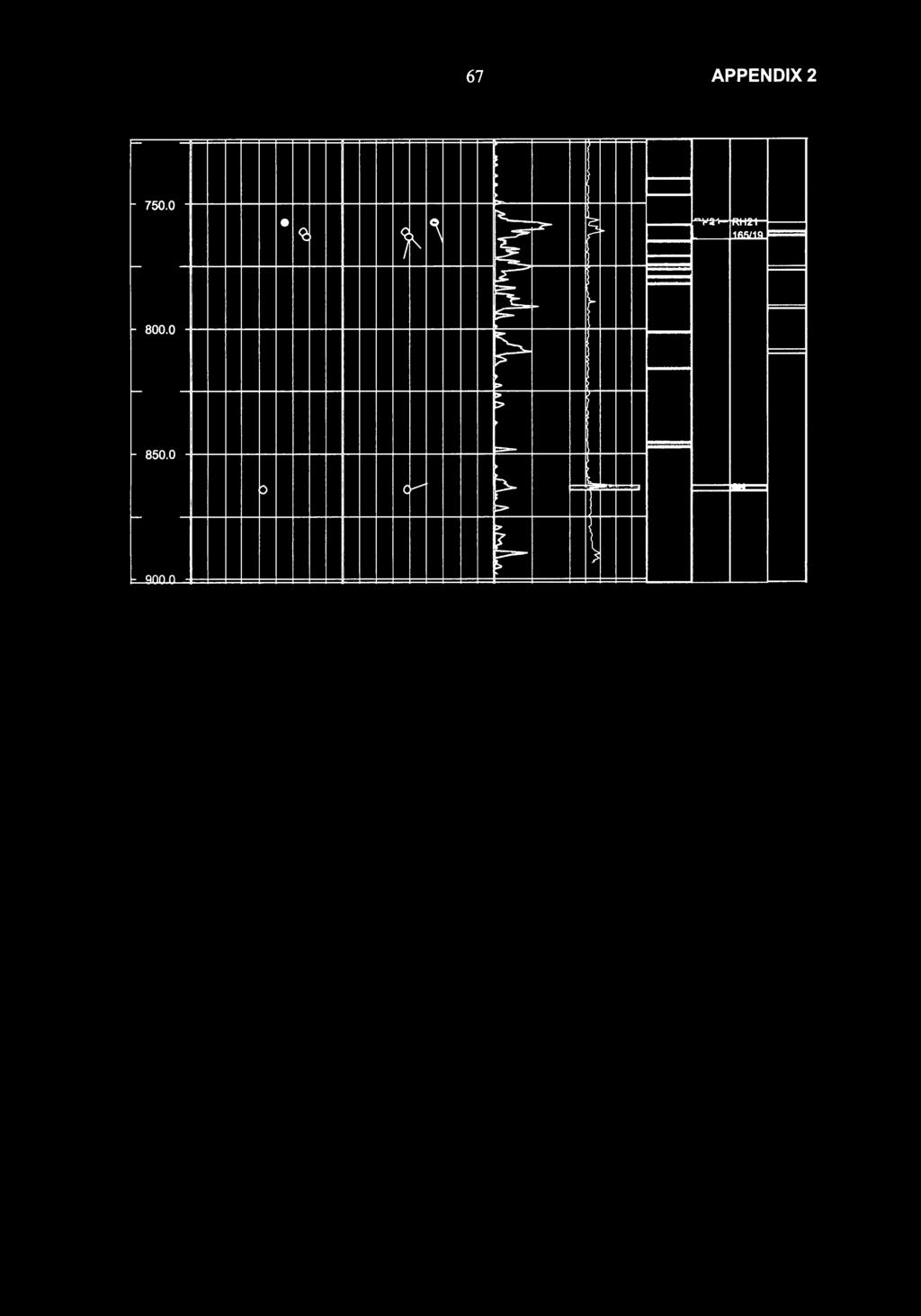
72 67 APPEND2

: Log(T): Hydraulic conductivity 2 m, log m/s Transmissivity, log m2/s")
73 68 APPEND 2 OL-KR7 ntersection angle: Open Tight Filled Op. si. e Ti. si. e Fi. si. Clay filled e Grain filled 0 Unknown Oriented fractures: d Certain observation / Uncertain observation Log(K): Log(T): Hydraulic conductivity 2 m, log m/s Transmissivity, log m2/s Lithology: Granite Structural section, structural model: D ntact rock D Fracture zone Structural section, hydr. model: D ntact rock Hydraulic feature Crushed zone Fracture zone Crushed zone Ri-class, based on engineering geological mapping: D Ri 111 Ri V Ri V Depth ntersection angle Oriented fractures Fract.freq. Log(K) Lith. Str Hyd Ri 1m:1700m /m m/s -5 KR07_ KR07 Log(T) v.v -10m2/s -5 - = h \ ' ro '""' U 1... U Ul


74 69 APPEND2 (lp ; 1- r ( lo 411 f t- > 17RH 0( :L'lnt :.!'b/1:.!' l:iloil:il n.n.o.u.., 126/12 f t- f > t- r t- 0 T =- '""'"" 5...::: 1' = r v== M t- r l$ { r- s-" ;
: Log(T): Hydraulic conductivity 2 m, log m/s Transmissivity, log m2/s Lithology: Granite D Quartz")

75 70 APPEND2 OL-KR8 ntersection angle: Open Tight Filled Op. si. Ti. si. Fi. si. Clay filled e Grain filled 0 Unknown Oriented fractures: if. Certain observation Uncertain observation Log(K): Log(T): Hydraulic conductivity 2 m, log m/s Transmissivity, log m2/s Lithology: Granite D Quartz feldspar gneiss Structural section, structural model: D lntact rock Structural section, hydr. model: D ntact rock Hydraulic feature Crushed zone Ri-class, based on engineering geological mapping: D Ri ll RiiV. RiV ntersection angle Oriented fractures Log(K) Lith. Ri m/s -5 Log(T)


76 71 APPEND2 () N 5. F? r ll 0 ) F= F= - F=? F= '!a_ =? ls""' { D'" = ::::: " 1 ( V L,..:.iS" = ===! 11R =... r;::- = > j i l - --" r- -,..,...,...,... = :::::1!!!! : =...- <r-
: Log(T): Hydraulic conductivity 2 m, log m/s Transmissivity, log m2/s Lithology: D Granite D Quartz feldspar gneiss Amphibolite D Tonalite")

77 72 APPEND2 OL-KR9 ntersection angle: Open Tight Filled Op. si. e Ti. si. e Fi. si. Clay filled Grain filled 0 Unknown Oriented fractures: ("'</ Certain observation t.._,...j Uncertain observation, colours as above Log(K): Log(T): Hydraulic conductivity 2 m, log m/s Transmissivity, log m2/s Lithology: D Granite D Quartz feldspar gneiss Amphibolite D Tonalite Structural section, structural model: D ntact rock Fracture zone - Crushed zone Structural section, hydr. model: D ntact rock Hydraulic feature Fracture zone Crushed zone Ri-class, based on engineering geological mapping: D Ri Ri V Ri V Depth 1m:1700m o ntersection angle 90 0 Oriented fractures Fract.freq. Log(K) /m m/s -5 Log(T) Lith. Str Hyd Ri KR09_ KR09_ v. v -10m2/s c la - lo 0 fo do lo l - c l,. p c la" (.411 (. C).. J 1 '/ )c C> t:=!!l ' rl = re lk Fa 11 0 N > 10: t-4 M... \ '-... v /J > <) ;;;;;;;;.. 0 r--- lr 1' l p ( "r /23 RH19B RH19B 1180/23 180/23 01-'"A.., F== lo 0 0 v r- v t fa ( io_ q [; l'b [. i:s" :.. Fa l:r ' \ "'-r-- > (
!< RH20A 0 Q r f\"\"' r- i=' l.")

78 73 APPEND2 4 \ C> ( p ( tr=- -..J > :> ::::>? r,.- ::>= r- )!< RH20A 0 Q r f""' r- i=' l.)f/10 f \ "V p=f"''.. RH20B RH20B /12 f t- s- 0 t- = 0 0- je jjii f t- t:::nn n 0 b "....,j { 3 - = ft'c F==?? :;
: Log(T): Hydraulic conductivity 2 m, log m/s Transmissivity, log m2/s Lithology: Granite Structural section, structural model: D ntact rock")

79 74 APPEND2 OL-KR10 ntersection angle: Open Tight Filled Op. si. e Ti. si. e Fi. si. Clay filled Grain filled 0 Unknown Oriented fractures:.. :::{' Certain observation Uncertain observation Log(K): Log(T): Hydraulic conductivity 2 m, log m/s Transmissivity, log m2/s Lithology: Granite Structural section, structural model: D ntact rock Fracture zone Crushed zone Structural section, hydr. model: D ntact rock Hydraulic feature Fracture zone Crushed zone Ri-class, based on engineering geological mapping: D Ri ll - Ri V Ri V Depth 1m:1700m o ntersection angle 90 0 Oriented fractures Fract.freq. Log(K) Lith. Str Hyd Ri /m m/s -5 KR10_ KR10_ Log(T) v.v -10 m/s t- r t p eo c 0 ' F F\ t \, l!:>!f=? '- f--._ - (\_ i <>c 7 3.: = ;;z 0 - r> 2-? ) lo r c ( l r :;:J d 0 V \ '\ - > RH?nA RH?OA /18

 9 n 10 \"\"' \ lo O ( t> =p ',(r 'r =- = 1-500.0 f- 550.")
80 75 APPEND2 F f J > 0? 1- o ;> f j: c f\?' ( p f [U \ ;&;;;;. l.l0/1"' l"'oil"'!51!1 = p lo t> lt p -!ii >- < < '\ ) 9 n 10 ""' \ lo O ( t> =p ',(r 'r =- = f ( [)., lr. "'' t:3::- ls ) c;=- )? 0 b b=- > ) k ("'\ ['- F <) > >

certain in foliated rock 9 7 6 22 parallel 4 1 5 rather parallel 2 2 not parallel 3 6 6 15 no foliation present 12 8 20 not clear 2 6 3 11 undefined 0 all")
81 Properties of the hydraulically conductive fractures 76 APPEND 3 1/4 KR4 KR7 KRS KR9 KR10 Total all (quite)certain Rock type KR4 KR7 KRS KR9 KR10 Total (quite)certain 0 GN GR Tonalite Quartz Amphibolite all GN GR Tonalite Quartz Amphibolite Lithological contacts KR4 KR7 KRS KR9 KR10 Total l(quite)certain at contact close to contact 0 no contacts all at contact close to contact no contacts Foliation KR4 KR7 KRS KR9 KR10 Total (quite)certain in foliated rock parallel rather parallel 2 2 not parallel no foliation present not clear undefined 0 all in foliated rock parallel rather parallel not parallel no foliation present not clear undefined Fracture type KR4 KR7 KRS KR9 KR10 Total (quite)certain Filled (Hi) Filled slickensided (Taha) Grain filled (Tamu) Open (Av) 0 Tight (Ti) all Filled (Ta) Filled slickensided (Taha) Grain filled (Tamu) Open (Av) Tight (Ti) PH,ET/JP-Fintact summary _results.xls\sheet1


82 Properties of the hydraulically conductive fractures 77 APPEND 3 2/4 Clay filled (Hisa) 1 Fracture infillings KR4 KR7 KR8 KR9 KR10 Total [(quite)certain Carbonates Sulphides Clay minerals Corroded 2 2 Chlorite Graphite 1 1 No reported infillings all Carbonates Sulphides Clay minerals Hollows Chlorite Graphite No reported infillings Shape of the fracture KR4 KR7 KR8 KR9 KR10 Total [(quite)certain planar (tasa) irregular (etas) undulating. (kaar) undefined all planar (tasa) irregular (etas) undulating (kaar) undefined Fracture surface KR4 KR7 KR8 KR9 KR10 Total [{g_uite)certain rough.(kark) semirough (pkar) smooth (sile) undefined all rough (kark) semirough (pkar) smooth ( sile) undefined Fracturing degree KR4 KR7 KR8 KR9 KR10 Total [(quite)certain 0-2 () all 0-2 () Structure type KR4 KR7 KR8 KR9 KR10 Total [(quite)certain Average rock () Hydraulic Feature Fracture zone Crushed zone all Average rock () Hydraulic Feature Fracture zone Crushed zone PH,ET /JP-Fintact summary _results.xls\sheet1
certain at contact close to contact no contacts all at contact close to contact no contacts Foliation (quite)certain in foliated rock parallel rather parallel not parallel no foliation present")
 Tight (Ti) all Filled (Ta) Filled slickensided (Taha) Grain filled (Tamu) Open (Av) Tight (Ti) KR4 82 9 0 9 0 KR7 79 56 10 44 0 0 3 0 0 0 KR4 KR7 9 0 91 17 1 3 4 79 95 KR4 KR7 82 44 22 33 0")
83 Properties of the hydraulically conductive fractures 78 APPEND3 3/4 Percentages Rock type l(quite)certain GN GR Tonalite Quartz Amphibolite all GN GR Tonalite Quartz Amphibolite Lithological contacts (quite)certain at contact close to contact no contacts all at contact close to contact no contacts Foliation (quite)certain in foliated rock parallel rather parallel not parallel no foliation present eos undefined all in foliated rock parallel rather parallel not parallel no foliation present eos undefined Fracture type (quite)certain Filled (Hi) Filled slickensided (Taha) Grain filled (Tamu) Open (Av) Tight (Ti) all Filled (Ta) Filled slickensided (Taha) Grain filled (Tamu) Open (Av) Tight (Ti) KR KR KR4 KR KR4 KR KR4 KR KR8 KR9 KR10 Total KR8 KR9 KR10 Total KR8 KR9 KR10 Total KR8 KR9 KR10 Total PH,ET/JP-Fintact summary_results.xls\sheet1
certain planar (tasa) irregular {etas) undulating {kaar) undefined all!")
certain 0-2 {) 3 4 all 0-2 () 3 4 Structure type (qulte)certain Average rock () Hydraulic Feature Fracture zone Crushed zone all Average rock () Hydraulic Feature")
84 Properties of the hydraulically conductive fractures 79 APPEND 3 4/4 Fracture infillings j(quite)certain Carbonates Sulphides Clay minerals Hollows Chlorite Graphite No reported infillings all Carbonates Sulphides Clay minerals Hollows Chlorite Graphite No reported infillings Shape of the fracture (quite)certain planar (tasa) irregular {etas) undulating {kaar) undefined all!planar {tasa) irregular {etas) undulating {kaar) undefined Fracture surface (quite)certain rough {kark) semirough {pkar) smooth {sile) undefined all rough {kark) semirough (pkar) smooth ( sile) undefined Fracturing degree l(quite)certain 0-2 {) 3 4 all 0-2 () 3 4 Structure type (qulte)certain Average rock () Hydraulic Feature Fracture zone Crushed zone all Average rock () Hydraulic Feature Fracture zone Crushed zone KR KR KR4 KR KR4 KR KR4 KR KR4 KR KR8 KR9 KR10 Total KR8 KR9 KR10 Total KR8 KR9 KR10 Total KR8 KR9 KR10 Total KR8 KR9 KR10 Total PH,ET/JP-Fintact summary_results.xls\sheet1

-depth(drill) T -depth-drilling depth, class certain - unear (T-depth-drilling depth, class certain)")
85 KR4 - Drilling fracture correlation s 0.00 R 2 = Q) (.) a L.. : "C drilling depth (m) depth(t}-depth(drill) tv-depth-drilling depth, class certain PH FT KR4-taulukko_ v2.xls\chart1 depth(hav)-depth(drill) T -depth-drilling depth, class certain - unear (T-depth-drilling depth, class certain) - Linear (tv-depth-drilling depth, class certain) )> ""C ""C m z c ><
 PH FT 8.10.2003 KR7 -taulukko v2.")
 - unear (tv-depth-drilling depth, class certain) )> \"\"0 \"\"0 m")
86 KR7 - Drilling fracture correlation o.4o 0.30 c Q) 0.20 =a o.1o Q) "' t--= y = x R 2 = drilling depth (m) PH FT KR7 -taulukko v2.xls\chart1 depth(t)-depth( drill) tv-depth-drilling depth, class certain depth(hav)-depth(drill) T-depth-drilling depth, class certain - unear (T-depth-drilling depth, class certain) - unear (tv-depth-drilling depth, class certain) )> ""0 ""0 m z c )(

 - Linear (T -depth-drilling depth,")
87 KRS - Drilling fracture correlation E' -; 0.2 () c Q) 0 :.0.s::::. c Q) "'C *xx x x v,... x x 4 V,... x -x')).( Jlf. _0 xj\ "% y = x V R 2 = :s: ll " y = x R 2 = Core sample broken m, depth errors possible * - y e 00 N drilling depth (m) T -depth-drilling depth tv-depth-drilling depth, class certain PH FT KR8-taulukko korj_ v3.xls\chart1 tv depth-drilling depth T -depth-drilling depth, class certain - Linear (tv-depth-drilling depth, class certain) - Linear (T -depth-drilling depth, class certain) )> "'tj "'tj m z c x.c:.
 -0.4 = -0.0008x + 0.1935 R 2 = 0.7673-0.5-0.")
 T -depth-drilling depth, class certain - unear")
88 KR9 - Drilling fracture correlation E... Q) 0 u c Q) -0.1 : Q) "'C -0.3 y = 3E-05x R 2 = (j,) -0.4 = x R 2 = drilling depth (m) T -depth-drilling depth tv-depth-drilling depth, class certain PH FT KR9-taulukko_ v2.xls\chart1 tv-depth-drilling depth - unear (T-depth-drilling depth, class certain) T -depth-drilling depth, class certain - unear (tv-depth-drilling depth, class certain) )> "'C "'C m z c ><


89 KR1 0 - Drilling fracture correlation 0.60 a> (.) c a> L : c... Cl. a> "' y = x R 2 = R 2 = drilling depth (m) T-depth-drilling fracture tv-depth-drilling depth, class certain PH FT KR 1 O-taulukko.xls\Chart1 tv-drilling fracture - unear (tv-depth-drilling depth, class certain) T -depth-drilling depth, class certain - unear (T-depth-drilling depth, class certain) )> "'tj "'tj m z c x.c:.
Capacity Utilization
 Capacity Utilization Tim Schöneberg 28th November Agenda Introduction Fixed and variable input ressources Technical capacity utilization Price based capacity utilization measure Long run and short run
Efficiency change over time
 Efficiency change over time Heikki Tikanmäki Optimointiopin seminaari 14.11.2007 Contents Introduction (11.1) Window analysis (11.2) Example, application, analysis Malmquist index (11.3) Dealing with panel
LYTH-CONS CONSISTENCY TRANSMITTER
 LYTH-CONS CONSISTENCY TRANSMITTER LYTH-INSTRUMENT OY has generate new consistency transmitter with blade-system to meet high technical requirements in Pulp&Paper industries. Insurmountable advantages are
Characterization of clay using x-ray and neutron scattering at the University of Helsinki and ILL
 Characterization of clay using x-ray and neutron scattering at the University of Helsinki and ILL Ville Liljeström, Micha Matusewicz, Kari Pirkkalainen, Jussi-Petteri Suuronen and Ritva Serimaa 13.3.2012
Results on the new polydrug use questions in the Finnish TDI data
 Results on the new polydrug use questions in the Finnish TDI data Multi-drug use, polydrug use and problematic polydrug use Martta Forsell, Finnish Focal Point 28/09/2015 Martta Forsell 1 28/09/2015 Esityksen
Information on preparing Presentation
 Information on preparing Presentation Seminar on big data management Lecturer: Spring 2017 20.1.2017 1 Agenda Hints and tips on giving a good presentation Watch two videos and discussion 22.1.2017 2 Goals
National Building Code of Finland, Part D1, Building Water Supply and Sewerage Systems, Regulations and guidelines 2007
 National Building Code of Finland, Part D1, Building Water Supply and Sewerage Systems, Regulations and guidelines 2007 Chapter 2.4 Jukka Räisä 1 WATER PIPES PLACEMENT 2.4.1 Regulation Water pipe and its
Other approaches to restrict multipliers
 Other approaches to restrict multipliers Heikki Tikanmäki Optimointiopin seminaari 10.10.2007 Contents Short revision (6.2) Another Assurance Region Model (6.3) Cone-Ratio Method (6.4) An Application of
16. Allocation Models
 16. Allocation Models Juha Saloheimo 17.1.27 S steemianalsin Optimointiopin seminaari - Sks 27 Content Introduction Overall Efficienc with common prices and costs Cost Efficienc S steemianalsin Revenue
On instrument costs in decentralized macroeconomic decision making (Helsingin Kauppakorkeakoulun julkaisuja ; D-31)
") On instrument costs in decentralized macroeconomic decision making (Helsingin Kauppakorkeakoulun julkaisuja ; D-31) Juha Kahkonen Click here if your download doesn"t start automatically On instrument costs
On instrument costs in decentralized macroeconomic decision making (Helsingin Kauppakorkeakoulun julkaisuja ; D-31) Juha Kahkonen Click here if your download doesn"t start automatically On instrument costs
Gap-filling methods for CH 4 data
 Gap-filling methods for CH 4 data Sigrid Dengel University of Helsinki Outline - Ecosystems known for CH 4 emissions; - Why is gap-filling of CH 4 data not as easy and straight forward as CO 2 ; - Gap-filling
1. SIT. The handler and dog stop with the dog sitting at heel. When the dog is sitting, the handler cues the dog to heel forward.
 START START SIT 1. SIT. The handler and dog stop with the dog sitting at heel. When the dog is sitting, the handler cues the dog to heel forward. This is a static exercise. SIT STAND 2. SIT STAND. The
Alternative DEA Models
 Mat-2.4142 Alternative DEA Models 19.9.2007 Table of Contents Banker-Charnes-Cooper Model Additive Model Example Data Home assignment BCC Model (Banker-Charnes-Cooper) production frontiers spanned by convex
The CCR Model and Production Correspondence
 The CCR Model and Production Correspondence Tim Schöneberg The 19th of September Agenda Introduction Definitions Production Possiblity Set CCR Model and the Dual Problem Input excesses and output shortfalls
On instrument costs in decentralized macroeconomic decision making (Helsingin Kauppakorkeakoulun julkaisuja ; D-31)
") On instrument costs in decentralized macroeconomic decision making (Helsingin Kauppakorkeakoulun julkaisuja ; D-31) Juha Kahkonen Click here if your download doesn"t start automatically On instrument costs
On instrument costs in decentralized macroeconomic decision making (Helsingin Kauppakorkeakoulun julkaisuja ; D-31) Juha Kahkonen Click here if your download doesn"t start automatically On instrument costs
Network to Get Work. Tehtäviä opiskelijoille Assignments for students. www.laurea.fi
 Network to Get Work Tehtäviä opiskelijoille Assignments for students www.laurea.fi Ohje henkilöstölle Instructions for Staff Seuraavassa on esitetty joukko tehtäviä, joista voit valita opiskelijaryhmällesi
The Viking Battle - Part Version: Finnish
 The Viking Battle - Part 1 015 Version: Finnish Tehtävä 1 Olkoon kokonaisluku, ja olkoon A n joukko A n = { n k k Z, 0 k < n}. Selvitä suurin kokonaisluku M n, jota ei voi kirjoittaa yhden tai useamman
Bounds on non-surjective cellular automata
 Bounds on non-surjective cellular automata Jarkko Kari Pascal Vanier Thomas Zeume University of Turku LIF Marseille Universität Hannover 27 august 2009 J. Kari, P. Vanier, T. Zeume (UTU) Bounds on non-surjective
On instrument costs in decentralized macroeconomic decision making (Helsingin Kauppakorkeakoulun julkaisuja ; D-31)
") On instrument costs in decentralized macroeconomic decision making (Helsingin Kauppakorkeakoulun julkaisuja ; D-31) Juha Kahkonen Click here if your download doesn"t start automatically On instrument costs
On instrument costs in decentralized macroeconomic decision making (Helsingin Kauppakorkeakoulun julkaisuja ; D-31) Juha Kahkonen Click here if your download doesn"t start automatically On instrument costs
Statistical Analysis and Modelling of Olkiluoto Structures
 Working Report 24-5 Statistical Analysis and Modelling of Olkiluoto Structures Pirjo HeiHi Tiina Vaittinen Pauli Saksa.Jorma ummela JP-Fintact Oy ovember 24 Working Reports contain information on work
Flow and Electrical Conductivity Measurements During Long-Term Pumping of Drillhole OL-KR6 at Olkiluoto, Results from June 2010 Measurements
 Working Report 2011-22 Flow and Electrical Conductivity Measurements During Long-Term Pumping of Drillhole OL-KR6 at Olkiluoto, Results from June 2010 Measurements Janne Pekkanen March 2011 POSIVA OY Olkiluoto
4x4cup Rastikuvien tulkinta
 4x4cup Rastikuvien tulkinta 4x4cup Control point picture guidelines Päivitetty kauden 2010 sääntöihin Updated for 2010 rules Säännöt rastikuvista Kilpailijoiden tulee kiinnittää erityistä huomiota siihen,
Slug-Tests in PP- and PVP-Holes at Olkiluoto in 2004
 Working Report 2005-76 Slug-Tests in PP- and PVP-Holes at Olkiluoto in 2004 Eveliina Tammisto Pirjo Hellä Jere Lahdenperä December 2005 POSIVA OY FI-27160 OLKILUOTO, FINLAND Tel +358-2-8372 31 Fax +358-2-8372
Slug-Tests in PP- and PVP-Holes at Olkiluoto in 2006
 Working Report 2007-93 Slug-Tests in PP- and PVP-Holes at Olkiluoto in 2006 Katriina Keskitalo Susanna Lindgren November 2007 POSIVA OY FI-27160 OLKILUOTO, FINLAND Tel +358-2-8372 31 Fax +358-2-8372 3709
T Statistical Natural Language Processing Answers 6 Collocations Version 1.0
 T-61.5020 Statistical Natural Language Processing Answers 6 Collocations Version 1.0 1. Let s start by calculating the results for pair valkoinen, talo manually: Frequency: Bigrams valkoinen, talo occurred
Slug-Tests in PP- and PVP-Holes at Olkiluoto in 2010
 Working Report 2011-40 Slug-Tests in PP- and PVP-Holes at Olkiluoto in 2010 Heikki Hinkkanen July 2011 POSIVA OY Olkiluoto FI-27160 EURAJOKI, FINLAND Tel +358-2-8372 31 Fax +358-2-8372 3809 Working Report
anna minun kertoa let me tell you
 anna minun kertoa let me tell you anna minun kertoa I OSA 1. Anna minun kertoa sinulle mitä oli. Tiedän että osaan. Kykenen siihen. Teen nyt niin. Minulla on oikeus. Sanani voivat olla puutteellisia mutta
Guidebook for Multicultural TUT Users
 1 Guidebook for Multicultural TUT Users WORKPLACE PIRKANMAA-hankkeen KESKUSTELUTILAISUUS 16.12.2010 Hyvää käytäntöä kehittämässä - vuorovaikutusopas kansainvälisille opiskelijoille TTY Teknis-taloudellinen
Statistical design. Tuomas Selander
 Statistical design Tuomas Selander 28.8.2014 Introduction Biostatistician Work area KYS-erva KYS, Jyväskylä, Joensuu, Mikkeli, Savonlinna Work tasks Statistical methods, selection and quiding Data analysis
Flow Measurements in ONKALO at Olkiluoto
 Working Report 2006-65 Flow Measurements in ONKALO at Olkiluoto Probe Holes and ONK-KR1 ONK-KR4, ONK-PVA1 and ONK-YPPL18 Markus Reiman Jari Pöllänen Juha Väisäsvaara September 2006 POSIVA OY FI-27160 OLKILUOTO,
LUONNOS RT 80260 EN AGREEMENT ON BUILDING WORKS 1 THE PARTIES. May 1998 1 (10)
") RT 80260 EN May 1998 1 (10) AGREEMENT ON BUILDING WORKS This agreement template is based on the General Terms and Conditions of Building Contracts YSE 1998 RT 16-10660, LVI 03-10277, Ratu 417-7, KH X4-00241.
RT 80260 EN May 1998 1 (10) AGREEMENT ON BUILDING WORKS This agreement template is based on the General Terms and Conditions of Building Contracts YSE 1998 RT 16-10660, LVI 03-10277, Ratu 417-7, KH X4-00241.
Land-Use Model for the Helsinki Metropolitan Area
 Land-Use Model for the Helsinki Metropolitan Area Paavo Moilanen Introduction & Background Metropolitan Area Council asked 2005: What is good land use for the transport systems plan? At first a literature
Uusi Ajatus Löytyy Luonnosta 4 (käsikirja) (Finnish Edition)
 (Finnish Edition)") Uusi Ajatus Löytyy Luonnosta 4 (käsikirja) (Finnish Edition) Esko Jalkanen Click here if your download doesn"t start automatically Uusi Ajatus Löytyy Luonnosta 4 (käsikirja) (Finnish Edition) Esko Jalkanen
Uusi Ajatus Löytyy Luonnosta 4 (käsikirja) (Finnish Edition) Esko Jalkanen Click here if your download doesn"t start automatically Uusi Ajatus Löytyy Luonnosta 4 (käsikirja) (Finnish Edition) Esko Jalkanen
C++11 seminaari, kevät Johannes Koskinen
 C++11 seminaari, kevät 2012 Johannes Koskinen Sisältö Mikä onkaan ongelma? Standardidraftin luku 29: Atomiset tyypit Muistimalli Rinnakkaisuus On multicore systems, when a thread writes a value to memory,
toukokuu 2011: Lukion kokeiden kehittämistyöryhmien suunnittelukokous
 Tuula Sutela toukokuu 2011: Lukion kokeiden kehittämistyöryhmien suunnittelukokous äidinkieli ja kirjallisuus, modersmål och litteratur, kemia, maantiede, matematiikka, englanti käsikirjoitukset vuoden
Constructive Alignment in Specialisation Studies in Industrial Pharmacy in Finland
 Constructive Alignment in Specialisation Studies in Industrial Pharmacy in Finland Anne Mari Juppo, Nina Katajavuori University of Helsinki Faculty of Pharmacy 23.7.2012 1 Background Pedagogic research
Työsuojelurahaston Tutkimus tutuksi - PalveluPulssi 11.3.2016. Peter Michelsson Wallstreet Asset Management Oy
 Työsuojelurahaston Tutkimus tutuksi - PalveluPulssi 11.3.2016 Peter Michelsson Wallstreet Asset Management Oy Wallstreet lyhyesti Perustettu vuonna 2006, SiPa toimilupa myönnetty 3/2014 Täysin kotimainen,
AYYE 9/ HOUSING POLICY
 AYYE 9/12 2.10.2012 HOUSING POLICY Mission for AYY Housing? What do we want to achieve by renting apartments? 1) How many apartments do we need? 2) What kind of apartments do we need? 3) To whom do we
ReFuel 70 % Emission Reduction Using Renewable High Cetane Number Paraffinic Diesel Fuel. Kalle Lehto, Aalto-yliopisto 5.5.
 ReFuel 70 % Emission Reduction Using Renewable High Cetane Number Paraffinic Diesel Fuel Kalle Lehto, Aalto-yliopisto 5.5.2011 Otaniemi ReFuel a three year research project (2009-2011) goal utilize the
KONEISTUSKOKOONPANON TEKEMINEN NX10-YMPÄRISTÖSSÄ
 KONEISTUSKOKOONPANON TEKEMINEN NX10-YMPÄRISTÖSSÄ https://community.plm.automation.siemens.com/t5/tech-tips- Knowledge-Base-NX/How-to-simulate-any-G-code-file-in-NX- CAM/ta-p/3340 Koneistusympäristön määrittely
ECVETin soveltuvuus suomalaisiin tutkinnon perusteisiin. Case:Yrittäjyyskurssi matkailualan opiskelijoille englantilaisen opettajan toteuttamana
 ECVETin soveltuvuus suomalaisiin tutkinnon perusteisiin Case:Yrittäjyyskurssi matkailualan opiskelijoille englantilaisen opettajan toteuttamana Taustaa KAO mukana FINECVET-hankeessa, jossa pilotoimme ECVETiä
ELEMET- MOCASTRO. Effect of grain size on A 3 temperatures in C-Mn and low alloyed steels - Gleeble tests and predictions. Period
 1 ELEMET- MOCASTRO Effect of grain size on A 3 temperatures in C-Mn and low alloyed steels - Gleeble tests and predictions Period 20.02-25.05.2012 Diaarinumero Rahoituspäätöksen numero 1114/31/2010 502/10
Oma sininen meresi (Finnish Edition)
") Oma sininen meresi (Finnish Edition) Hannu Pirilä Click here if your download doesn"t start automatically Oma sininen meresi (Finnish Edition) Hannu Pirilä Oma sininen meresi (Finnish Edition) Hannu Pirilä
Oma sininen meresi (Finnish Edition) Hannu Pirilä Click here if your download doesn"t start automatically Oma sininen meresi (Finnish Edition) Hannu Pirilä Oma sininen meresi (Finnish Edition) Hannu Pirilä
Use of spatial data in the new production environment and in a data warehouse
 Use of spatial data in the new production environment and in a data warehouse Nordic Forum for Geostatistics 2007 Session 3, GI infrastructure and use of spatial database Statistics Finland, Population
WindPRO version joulu 2012 Printed/Page :42 / 1. SHADOW - Main Result
 SHADOW - Main Result Assumptions for shadow calculations Maximum distance for influence Calculate only when more than 20 % of sun is covered by the blade Please look in WTG table 13.6.2013 19:42 / 1 Minimum
Returns to Scale II. S ysteemianalyysin. Laboratorio. Esitelmä 8 Timo Salminen. Teknillinen korkeakoulu
 Returns to Scale II Contents Most Productive Scale Size Further Considerations Relaxation of the Convexity Condition Useful Reminder Theorem 5.5 A DMU found to be efficient with a CCR model will also be
Rotarypiiri 1420 Piiriapurahoista myönnettävät stipendit
 Rotarypiiri 1420 Piiriapurahoista myönnettävät stipendit Ø Rotarypiiri myöntää stipendejä sille osoitettujen hakemusten perusteella ensisijaisesti rotaryaatteen mukaisiin tarkoituksiin. Ø Stipendejä myönnetään
WindPRO version joulu 2012 Printed/Page :47 / 1. SHADOW - Main Result
 SHADOW - Main Result Assumptions for shadow calculations Maximum distance for influence Calculate only when more than 20 % of sun is covered by the blade Please look in WTG table WindPRO version 2.8.579
( ,5 1 1,5 2 km
 Tuulivoimala Rakennukset Asuinrakennus Liikerak. tai Julkinen rak. Lomarakennus Teollinen rakennus Kirkollinen rakennus Varjostus "real case" h/a 1 h/a 8 h/a 20 h/a 4 5 3 1 2 6 7 8 9 10 0 0,5 1 1,5 2 km
Information on Finnish Language Courses Spring Semester 2018 Päivi Paukku & Jenni Laine Centre for Language and Communication Studies
 Information on Finnish Language Courses Spring Semester 2018 Päivi Paukku & Jenni Laine 4.1.2018 Centre for Language and Communication Studies Puhutko suomea? -Hei! -Hei hei! -Moi! -Moi moi! -Terve! -Terve
TEST REPORT Nro VTT-S Air tightness and strength tests for Furanflex exhaust air ducts
 TEST REPORT Nro VTT-S-04515-08 19.5.008 Air tightness and strength tests for Furanflex exhaust air ducts Requested by: Hormex Oy TEST REPORT NRO VTT-S-04515-08 1 () Requested by Order Hormex Oy Linnanherrankuja
Metsälamminkankaan tuulivoimapuiston osayleiskaava
 VAALAN KUNTA TUULISAIMAA OY Metsälamminkankaan tuulivoimapuiston osayleiskaava Liite 3. Varjostusmallinnus FCG SUUNNITTELU JA TEKNIIKKA OY 12.5.2015 P25370 SHADOW - Main Result Assumptions for shadow calculations
( ( OX2 Perkkiö. Rakennuskanta. Varjostus. 9 x N131 x HH145
 OX2 9 x N131 x HH145 Rakennuskanta Asuinrakennus Lomarakennus Liike- tai julkinen rakennus Teollinen rakennus Kirkko tai kirkollinen rak. Muu rakennus Allas Varjostus 1 h/a 8 h/a 20 h/a 0 0,5 1 1,5 2 km
7.4 Variability management
 7.4 Variability management time... space software product-line should support variability in space (different products) support variability in time (maintenance, evolution) 1 Product variation Product
MEETING PEOPLE COMMUNICATIVE QUESTIONS
 Tiistilän koulu English Grades 7-9 Heikki Raevaara MEETING PEOPLE COMMUNICATIVE QUESTIONS Meeting People Hello! Hi! Good morning! Good afternoon! How do you do? Nice to meet you. / Pleased to meet you.
Valuation of Asian Quanto- Basket Options
 Valuation of Asian Quanto- Basket Options (Final Presentation) 21.11.2011 Thesis Instructor and Supervisor: Prof. Ahti Salo Työn saa tallentaa ja julkistaa Aalto-yliopiston avoimilla verkkosivuilla. Muilta
Tynnyrivaara, OX2 Tuulivoimahanke. ( Layout 9 x N131 x HH145. Rakennukset Asuinrakennus Lomarakennus 9 x N131 x HH145 Varjostus 1 h/a 8 h/a 20 h/a
 , Tuulivoimahanke Layout 9 x N131 x HH145 Rakennukset Asuinrakennus Lomarakennus 9 x N131 x HH145 Varjostus 1 h/a 8 h/a 20 h/a 0 0,5 1 1,5 km 2 SHADOW - Main Result Assumptions for shadow calculations
Kysymys 5 Compared to the workload, the number of credits awarded was (1 credits equals 27 working hours): (4)
: (4)") Tilasto T1106120-s2012palaute Kyselyn T1106120+T1106120-s2012palaute yhteenveto: vastauksia (4) Kysymys 1 Degree programme: (4) TIK: TIK 1 25% ************** INF: INF 0 0% EST: EST 0 0% TLT: TLT 0 0% BIO:
Tilasto T1106120-s2012palaute Kyselyn T1106120+T1106120-s2012palaute yhteenveto: vastauksia (4) Kysymys 1 Degree programme: (4) TIK: TIK 1 25% ************** INF: INF 0 0% EST: EST 0 0% TLT: TLT 0 0% BIO:
Reliable diagnostic support Ultra-light design
 EN Powerful illumination Intelligent charging management Reliable diagnostic support Ultra-light design VISIOMED Optima UV original scale 1:1 VISIOMED Optima Quality Made Easy and an illumination close
TM ETRS-TM35FIN-ETRS89 WTG
 SHADOW - Main Result Assumptions for shadow calculations Maximum distance for influence Calculate only when more than 20 % of sun is covered by the blade Please look in WTG table 22.12.2014 11:33 / 1 Minimum
,0 Yes ,0 120, ,8
 SHADOW - Main Result Calculation: Alue 2 ( x 9 x HH120) TuuliSaimaa kaavaluonnos Assumptions for shadow calculations Maximum distance for influence Calculate only when more than 20 % of sun is covered
TM ETRS-TM35FIN-ETRS89 WTG
 SHADOW - Main Result Calculation: N117 x 9 x HH141 Assumptions for shadow calculations Maximum distance for influence Calculate only when more than 20 % of sun is covered by the blade Please look in WTG
FinFamily PostgreSQL installation ( ) FinFamily PostgreSQL
 FinFamily PostgreSQL") FinFamily PostgreSQL 1 Sisällys / Contents FinFamily PostgreSQL... 1 1. Asenna PostgreSQL tietokanta / Install PostgreSQL database... 3 1.1. PostgreSQL tietokannasta / About the PostgreSQL database...
FinFamily PostgreSQL 1 Sisällys / Contents FinFamily PostgreSQL... 1 1. Asenna PostgreSQL tietokanta / Install PostgreSQL database... 3 1.1. PostgreSQL tietokannasta / About the PostgreSQL database...
make and make and make ThinkMath 2017
 Adding quantities Lukumäärienup yhdistäminen. Laske yhteensä?. Countkuinka howmonta manypalloja ballson there are altogether. and ja make and make and ja make on and ja make ThinkMath 7 on ja on on Vaihdannaisuus
TM ETRS-TM35FIN-ETRS89 WTG
 SHADOW - Main Result Assumptions for shadow calculations Maximum distance for influence Calculate only when more than 20 % of sun is covered by the blade Please look in WTG table 5.11.2013 16:44 / 1 Minimum
3 9-VUOTIAIDEN LASTEN SUORIUTUMINEN BOSTONIN NIMENTÄTESTISTÄ
 Puhe ja kieli, 27:4, 141 147 (2007) 3 9-VUOTIAIDEN LASTEN SUORIUTUMINEN BOSTONIN NIMENTÄTESTISTÄ Soile Loukusa, Oulun yliopisto, suomen kielen, informaatiotutkimuksen ja logopedian laitos & University
Information on Finnish Language Courses Spring Semester 2017 Jenni Laine
 Information on Finnish Language Courses Spring Semester 2017 Jenni Laine 4.1.2017 KIELIKESKUS LANGUAGE CENTRE Puhutko suomea? Do you speak Finnish? -Hei! -Moi! -Mitä kuuluu? -Kiitos, hyvää. -Entä sinulle?
TM ETRS-TM35FIN-ETRS89 WTG
 SHADOW - Main Result Assumptions for shadow calculations Maximum distance for influence Calculate only when more than 20 % of sun is covered by the blade Please look in WTG table WindPRO version 2.9.269
Sisällysluettelo Table of contents
 Sisällysluettelo Table of contents OTC:n Moodlen käyttöohje suomeksi... 1 Kirjautuminen Moodleen... 2 Ensimmäinen kirjautuminen Moodleen... 2 Salasanan vaihto... 2 Oma käyttäjäprofiili... 3 Työskentely
TM ETRS-TM35FIN-ETRS89 WTG
 SHADOW - Main Result Assumptions for shadow calculations Maximum distance for influence Calculate only when more than 20 % of sun is covered by the blade Please look in WTG table WindPRO version 2.8.579
TIEKE Verkottaja Service Tools for electronic data interchange utilizers. Heikki Laaksamo
 TIEKE Verkottaja Service Tools for electronic data interchange utilizers Heikki Laaksamo TIEKE Finnish Information Society Development Centre (TIEKE Tietoyhteiskunnan kehittämiskeskus ry) TIEKE is a neutral,
Choose Finland-Helsinki Valitse Finland-Helsinki
 Write down the Temporary Application ID. If you do not manage to complete the form you can continue where you stopped with this ID no. Muista Temporary Application ID. Jos et onnistu täyttää lomake loppuun
TM ETRS-TM35FIN-ETRS89 WTG
 SHADOW - Main Result Assumptions for shadow calculations Maximum distance for influence Calculate only when more than 20 % of sun is covered by the blade Please look in WTG table WindPRO version 2.8.579
I. Principles of Pointer Year Analysis
 I. Principles of Pointer Year Analysis Fig 1. Maximum (red) and minimum (blue) pointer years. 1 Fig 2. Principle of pointer year calculation. Fig 3. Skeleton plot graph created by Kinsys/Kigraph programme.
MUSEOT KULTTUURIPALVELUINA
 Elina Arola MUSEOT KULTTUURIPALVELUINA Tutkimuskohteena Mikkelin museot Opinnäytetyö Kulttuuripalvelujen koulutusohjelma Marraskuu 2005 KUVAILULEHTI Opinnäytetyön päivämäärä 25.11.2005 Tekijä(t) Elina
TM ETRS-TM35FIN-ETRS89 WTG
 SHADOW - Main Result Assumptions for shadow calculations Maximum distance for influence Calculate only when more than 20 % of sun is covered by the blade Please look in WTG table WindPRO version 2.8.579
TM ETRS-TM35FIN-ETRS89 WTG
 SHADOW - Main Result Assumptions for shadow calculations Maximum distance for influence Calculate only when more than 20 % of sun is covered by the blade Please look in WTG table WindPRO version 2.8.579
TM ETRS-TM35FIN-ETRS89 WTG
 SHADOW - Main Result Assumptions for shadow calculations Maximum distance for influence Calculate only when more than 20 % of sun is covered by the blade Please look in WTG table WindPRO version 2.8.579
1. Liikkuvat määreet
 1. Liikkuvat määreet Väitelauseen perussanajärjestys: SPOTPA (subj. + pred. + obj. + tapa + paikka + aika) Suora sanajärjestys = subjekti on ennen predikaattia tekijä tekeminen Alasääntö 1: Liikkuvat määreet
S Sähkön jakelu ja markkinat S Electricity Distribution and Markets
 S-18.3153 Sähkön jakelu ja markkinat S-18.3154 Electricity Distribution and Markets Voltage Sag 1) Kolmivaiheinen vastukseton oikosulku tapahtuu 20 kv lähdöllä etäisyydellä 1 km, 3 km, 5 km, 8 km, 10 km
LX 70. Ominaisuuksien mittaustulokset 1-kerroksinen 2-kerroksinen. Fyysiset ominaisuudet, nimellisarvot. Kalvon ominaisuudet
 LX 70 % Läpäisy 36 32 % Absorptio 30 40 % Heijastus 34 28 % Läpäisy 72 65 % Heijastus ulkopuoli 9 16 % Heijastus sisäpuoli 9 13 Emissiivisyys.77.77 Auringonsuojakerroin.54.58 Auringonsäteilyn lämmönsiirtokerroin.47.50
TM ETRS-TM35FIN-ETRS89 WTG
 VE1 SHADOW - Main Result Calculation: 8 x Nordex N131 x HH145m Assumptions for shadow calculations Maximum distance for influence Calculate only when more than 20 % of sun is covered by the blade Please
The role of 3dr sector in rural -community based- tourism - potentials, challenges
 The role of 3dr sector in rural -community based- tourism - potentials, challenges Lappeenranta, 5th September 2014 Contents of the presentation 1. SEPRA what is it and why does it exist? 2. Experiences
MIKES, Julkaisu J3/2000 MASS COMPARISON M3. Comparison of 1 kg and 10 kg weights between MIKES and three FINAS accredited calibration laboratories
 MITTATEKNIIKAN KESKUS CENTRE FOR METROLOGY AND ACCREDITATION Julkaisu J3/2000 MASS COMPARISON M3 Comparison of 1 kg and 10 kg weights between MIKES and three FINAS accredited calibration laboratories Kari
KMTK lentoestetyöpaja - Osa 2
 KMTK lentoestetyöpaja - Osa 2 Veijo Pätynen 18.10.2016 Pasila YHTEISTYÖSSÄ: Ilmailun paikkatiedon hallintamalli Ilmailun paikkatiedon hallintamalli (v0.9 4.3.2016) 4.4 Maanmittauslaitoksen rooli ja vastuut...
Group 2 - Dentego PTH Korvake. Peer Testing Report
 Group 2 - Dentego PTH Korvake Peer Testing Report Revisions Version Date Author Description 1.0 Henrik Klinkmann First version Table of Contents Contents Revisions... 2 Table of Contents... 2 Testing...
Curriculum. Gym card
 A new school year Curriculum Fast Track Final Grading Gym card TET A new school year Work Ethic Detention Own work Organisation and independence Wilma TMU Support Services Well-Being CURRICULUM FAST TRACK
Tutkimusdata ja julkaiseminen Suomen Akatemian ja EU:n H2020 projekteissa
 Tutkimusdata ja julkaiseminen Suomen Akatemian ja EU:n H2020 projekteissa Tutkimusasiamies Kaisa Männikkö Tutkimus- ja innovaatiopalvelut Suomen Akatemian projektit Suomen Akatemia kehottaa avoimeen tieteelliseen
Development of a Hydrogeological Discrete Fracture Network Model for the Olkiluoto Site Descriptive Model Working Report
 Working Report 2009-61 Development of a Hydrogeological Discrete Fracture Network Model for the Olkiluoto Site Descriptive Model 2008 Lee Hartley, Jaap Hoek, David Swan David Roberts, Steve Joyce Sven
TM ETRS-TM35FIN-ETRS89 WTG
 SHADOW - Main Result Assumptions for shadow calculations Maximum distance for influence Calculate only when more than 20 % of sun is covered by the blade Please look in WTG table WindPRO version 2.8.579
Rakennukset Varjostus "real case" h/a 0,5 1,5
 Tuulivoimala Rakennukset Asuinrakennus Liikerak. tai Julkinen rak. Lomarakennus Teollinen rakennus Kirkollinen rakennus Varjostus "real case" h/a 1 h/a 8 h/a 20 h/a 1 2 3 5 8 4 6 7 9 10 0 0,5 1 1,5 2 km
EUROOPAN PARLAMENTTI
 EUROOPAN PARLAMENTTI 2004 2009 Kansalaisvapauksien sekä oikeus- ja sisäasioiden valiokunta 2008/0101(CNS) 2.9.2008 TARKISTUKSET 9-12 Mietintöluonnos Luca Romagnoli (PE409.790v01-00) ehdotuksesta neuvoston
HARJOITUS- PAKETTI A
 Logistiikka A35A00310 Tuotantotalouden perusteet HARJOITUS- PAKETTI A (6 pistettä) TUTA 19 Luento 3.Ennustaminen County General 1 piste The number of heart surgeries performed at County General Hospital
Information on Finnish Courses Autumn Semester 2017 Jenni Laine & Päivi Paukku Centre for Language and Communication Studies
 Information on Finnish Courses Autumn Semester 2017 Jenni Laine & Päivi Paukku 24.8.2017 Centre for Language and Communication Studies Puhutko suomea? -Hei! -Hei hei! -Moi! -Moi moi! -Terve! -Terve terve!
Toppila/Kivistö 10.01.2013 Vastaa kaikkin neljään tehtävään, jotka kukin arvostellaan asteikolla 0-6 pistettä.
 ..23 Vastaa kaikkin neljään tehtävään, jotka kukin arvostellaan asteikolla -6 pistettä. Tehtävä Ovatko seuraavat väittämät oikein vai väärin? Perustele vastauksesi. (a) Lineaarisen kokonaislukutehtävän
Tarua vai totta: sähkön vähittäismarkkina ei toimi? 11.2.2015 Satu Viljainen Professori, sähkömarkkinat
 Tarua vai totta: sähkön vähittäismarkkina ei toimi? 11.2.2015 Satu Viljainen Professori, sähkömarkkinat Esityksen sisältö: 1. EU:n energiapolitiikka on se, joka ei toimi 2. Mihin perustuu väite, etteivät
Small Number Counts to 100. Story transcript: English and Blackfoot
 Small Number Counts to 100. Story transcript: English and Blackfoot Small Number is a 5 year-old boy who gets into a lot of mischief. He lives with his Grandma and Grandpa, who patiently put up with his
Capacity utilization
 Mat-2.4142 Seminar on optimization Capacity utilization 12.12.2007 Contents Summary of chapter 14 Related DEA-solver models Illustrative examples Measure of technical capacity utilization Price-based measure
SSTY:n EMC-seminaari. EMC ja sähköisten lääkintälaitteiden standardit. Ari Honkala SESKO ry
 SSTY:n EMC-seminaari EMC ja sähköisten lääkintälaitteiden standardit SESKO ry 2016-10-04 Tässä esityksessä käsitellään Yleistä täydentävistä (collateral, -1 sarja, horisontaaliset) ja eritysvaatimuksia
OFFICE 365 OPISKELIJOILLE
 OFFICE 365 OPISKELIJOILLE Table of Contents Articles... 3 Ohjeet Office 365 käyttöönottoon... 4 One Driveen tallennetun videon palauttaminen oppimisympäristön palautuskansioon... 5 Changing default language