MIVA. Mikrorakenteisten metallituotteiden joustava valmistus
|
|
|
- Kauko Heino
- 7 vuotta sitten
- Katselukertoja:
Transkriptio

1 MIVA Mikrorakenteisten metallituotteiden joustava valmistus TEKES, diaarionro 1097/31/08, päätösnro 40186/ Loppuraportti toim. Jari Larkiola, VTT VTT TECHNICAL RESEARCH CENTRE OF FINLAND Metallimiehenkuja 6, Espoo P.O.Box 1000, FI VTT, FINLAND Tel Fax Business ID
2 2 (9) TEKES diaarionro 1097/31/08, päätösnro 40186/08 Projektin nimi Projektin numero/lyhytnimi Mikrorakenteisten metallituotteiden joustava valmistus 29985/MIVA Raportin laatija(t) Sivujen/liitesivujen lukumäärä Koonnut Jari Larkiola 9/317 Avainsanat Raportin numero UFG metals, SPD, severe plastic deformation, ECAP VTT-R Tiivistelmä Tuotteiden kestävyys ja kuormitettavuus pohjautuvat tuotteen materiaaliominaisuuksiin ja muotoon. Yksi uusi ja tehokas tapa parantaa tuotteen ominaisuuksia valmistusvaiheessa on SPD-menetelmä (Severe Plastic Deformation). SPD -menetelmissä voimakas valmistuksen aikana tapahtuva muokkaus - samalla kun se antaa tuotteelle muodon - pienentää materiaalin raekokoa mikroluokkaan. Mikrorakenteisessa materiaalissa raekoko on alle 1 µm (normaalisti raekoko on luokkaa µm). Raekoon pienentäminen parantaa merkittävästi mm. mekaanisia ominaisuuksia. Teollisuus ei vielä ole alkanut valmistaa mikrorakenteisia raaka-aineita ja aihioita. Tämä johtuu pääosin siitä, että ei ole olemassa hyvin toimivaa jatkuvaan prosessiin sopivaa SPDmenetelmää. Tämä luo mahdollisuuden saavuttaa kilpailuetua valmistamalla SPDkomponentteja. Tämän hankkeen tavoitteena oli kehittää ja hyödyntää SDP -tekniikkaa, ko. prosessiin sopivia materiaaleja sekä hyödyntää menetelmää valmistavassa kappaletavarateollisuudessa. Projektissa kartoitettiin laajasti ufg materiaalien valmistustekniikoita, ominaisuuksia ja käyttömahdollisuuksia. Yritysesimerkkien kohdalla tavoitteita ei täysin saavutettu. Kuitenkin yritykset jatkavat kokeita tuotannon sopivasti salliessa. Tällöin mahdollisuus tavoitteissa määritettyihin ratkaisuihin on edelleen olemassa ja hankkeen vaikutus yritysten uusiin tuotteisiin ja liikevaihtoon nähdään myöhemmin. Yksi yritys jatkaa SPD-valmistusprosessin kehitystä ja tavoitteena heillä on uuden SPD-materiaalien tuominen markkinoille Raportissa esitetään hankkeen tuloksia yksityiskohtaisemmin sekä projektin aikana tehdyt julkaisut. Luottamuksellisuus Espoossa Laatija julkinen Tarkastaja Hyväksyjä Jari Larkiola, Asiakaspäällikkö VTT:n yhteystiedot VTT, PL 1000, FI-0204 VTT Hannu Martikainen, Erikoistutkija Riikka Virkkunen, Teknologiapäällikkö VTT:n nimen käyttäminen mainonnassa tai tämän raportin osittainen julkaiseminen on sallittu vain VTT:ltä saadun kirjallisen luvan perusteella.
3 3 (9) Sisällysluettelo 1. Taustaa 2. Tavoitteet 3. Toteutus 4. Tulokset 4.1 Kirjallisuusselvitykset 4.2 ECAPE 4.3 Austeniittinen piippumateriaali 4.4 UFG ja valssaus 4.5 Ultraluja lanka ja korkeahiilinen teräs 4.6 UFG materiaalit ja menetelmäkehitys SPD ominaisuuksien tutkimiseen 5. Yhteenveto Liitteet Liite 1.1 Liite 1.2 Liite 1.3 Liite 2.1 Liite 3.1 Liite 3.2 Liite 4.1 Liite 5.1 Liite 6.1 Ultra-high Strength Wire Rods and Wires Based on Severe Plastic Deformation (SPD) and Ultrafine-grained (UFG) Microstructure Leijun Li* and Jouko Virta (VTT) *Visiting Professor from Utah State University, Logan, Utah, USA Severe Plastic Deformation (SPD) Angelina Gianni (Aalto University) UFG ferrous metals produced by SPD Andrzej Rosochowski, University of Strathclyde, Glasgow UK ECAPE-muotti Hannu Martikainen (VTT) Kiväärin piiput Antti Korhonen (Aalto) ja Jari Larkiola (VTT) Ruostumattomien martensiittisten terästen lämpökäsittelystä Antti Korhonen (Aalto) ja Jari Larkiola (VTT) UFG ja valssaus, kalvoja Jari Larkiola (VTT) ja Veli-Tapani Kuokkala (TTY) Ultraluja lanka, kalvoja Jouko Virta (VTT) ECAP-prosessoitujen metallien rakenne ja mekaaniset ominaisuudet Juho Rajamäki (TTY)
4 4 (9) Liite 6.2 Liite 6.3 Liite 6.4 Liite 6.5 Liite 6.6 Liite 6.7 Liite 6.8 Liite 6.9 Liite 6.10 Liite 6.11 Dynamic Torsion Properties of Ultrafine Grained Aluminum Mikko Hokka, Jari Kokkonen, Jeremy Seidt, Thomas Matrka, Amos Gilat, Veli-TapaniKuokkala Compression Behavior of Near-UFG AZ31 Mg-Alloy at High Strain Rates Mikko Hokka, Jeremy Seidt, Thomas Matrka, Amos Gilat, Veli-Tapani Kuokkala, JuhaNykänen, Sören Müller Characterization of the mechanical behavior of ultrafinegrained metals using digital image correlation M. Hokka, J. Seidt, T. Matrka, A. Gilat, V.-T. Kuokkala, J. Kokkonen and S. Müller Metallien ECAP ja HESP prosessointi Okko Niskanen High Strain Rate Torsion Properties of Ultrafine-Grained Aluminum Mikko Hokka, Jari Kokkonen, Jeremy Seidt, Thomas Matrka, Amos Gilat, Veli-TapaniKuokkala Metallien SPD.prosessointi, mikrorakenteet ja ominaisuudet Mimmi Viherkoski Mechanical Properties of Austenitic Manganese Steel Ville Viberg Recrystallization and thermal stability of ECAP processed aluminum Pasi Hakonen Digital Image Correlation in Mechanical Materials Testing Mikko Hokka, Amos Gilat, and Veli-Tapani Kuokkala Nanocrystalline and Ultrafine Grain Size Steels by Severe Plastic Deformation - Sheet Steels and Surface Nanocrystallization Mikko Hokka
5 5 (9) 1. Taustaa Tuotteiden kestävyys ja kuormitettavuus pohjautuvat tuotteen materiaaliominaisuuksiin ja muotoon. Yksi uusi ja tehokas tapa parantaa tuotteen ominaisuuksia valmistusvaiheessa on SPDmenetelmä (Severe Plastic Deformation). SPD -menetelmissä voimakas valmistuksen aikana tapahtuva muokkaus - samalla kun se antaa tuotteelle muodon - pienentää materiaalin raekokoa mikroluokkaan. Mikrorakenteisessa materiaalissa raekoko on alle 1 µm (normaalisti raekoko on luokkaa µm). Raekoon pienentäminen parantaa merkittävästi mm. mekaanisia ominaisuuksia. 2. Tavoitteet Raekoon pienentäminen parantaa merkittävästi materiaalin ominaisuuksia. Mikrorakenteisilla tuotteilla on poikkeavat ominaisuudet ja ominaisuusyhdistelmät: esimerkiksi korkea lujuus, hyvä väsymiskestävyys, sitkeys ja korroosionkestävyys sekä hyvä jatkovalmistettavuus (työstettävyys, superplastiset ominaisuudet). Mikrorakenteisten tuotteiden käyttöalue on laaja, kuten avaruustekniikka, kuljetustekniikka, terveydenhoitoon liittyvät laitteet ja komponentit, urheiluvälineet, elintarvike ja kemianteollisuus, elektroniikka ja puolustussektori. SPD-menetelmiä voidaan hyödyntää joko raaka-aineen tai aihion valmistusvaiheessa tai lopullisen tuotteen valmistuksen yhteydessä. Konepaja voi räätälöidä tuotteen vastaamaan paremmin käyttövaatimuksia. Menetelmillä voidaan esimerkiksi parantaa perusmateriaalin lujuutta, komponentin pinnan väsymisominaisuuksia ja korroosionkestävyyttä. Mikrorakenteisen tuotteen ominaisuuksia voidaan vielä lopuksi muuttaa lämpökäsittelyllä: raekoko ja ominaisuudet voidaan muuttaa kappaleessa paikkakohtaisesti! Teollisuus ei vielä ole alkanut valmistaa mikrorakenteisia raaka-aineita ja aihioita. Tämä johtuu pääosin siitä, että ei ole olemassa hyvin toimivaa jatkuvaan prosessiin sopivaa SPD-menetelmää. Tämä luo mahdollisuuden saavuttaa kilpailuetua valmistamalla SPD-komponentteja. Konepajaan sopivia koko kappaleen rakennetta muokkaavia menetelmiä ovat mm. ECAP (Equal Channel Angular Pressing) ja MAC (Multiaxial Compression). Kappaleen pinnan käsittelyyn sopivia menetelmiä ovat mm CRPD (Circulation Rolling Plastic Deformation) ja HESP (High Energy Shot Peening). Hankkeen tavoitteena oli kehittää SDP tekniikkaa ja sopivaa menetelmää valmistavan kappaletavarateollisuuden käyttöön. 3. Toteutus Hankkeessa kehitettiin menetelmiä ja lähtömateriaaleja mikrorakenteisten tuotteiden valmistukseen. Lisäksi tutkittiin ECAP-prosessin toimintaa omilla laitteistoilla ja työkaluilla. Sovelluksia testattiin osallistuvien yritysten esimerkeissä. Pääsääntöisesti TTY keskittyi tutkimukseen, joka liittyi dynaamisten ilmiöiden hyödyntämiseen ko. materiaaleilla ja valmistettujen materiaalien analysointiin. TKK:lla tutkittiin lämpökäsittelyn ja pinnoituksen vaikutusta SPD-prosessissa. VTT:llä tehtiin menetelmäkehityksestä sekä kokeita yritysten sovelluksiin liittyen.


 on lisännyt kansainvälistä")
. 4.")

6 6 (9) 4. Tulokset MIVA-hankkeessa tehtiin suuri määrä kirjallisuuskatsauksia ja selvitettiin SPD-teknologian nykytilaa. 4.1 Kirjallisuusselvitykset Hanke aloitettiin kattavilla kirjallisuusselvityksillä. Mikro/nanorakenteisten metallituotteiden valmistusta sekä prosessointia on käsitelty useissa tutkimuksen aikana kirjoitetussa selvityksessä, Liitteet Hankkeessa ja selvitysten tekemisessä oli mukana myös ulkomaisia alan asiantuntijoita: Professori Leijun Li (Utah University) ja Dr A. Rosochowski (Strahclyde University, Glasgow). Projektiin liittynyt tutkimusvierailu The Ohio State Universityyn, USA, (TkT Mikko Hokka) on lisännyt kansainvälistä yhteistyötä ja on jo johtanut jatkoyhteistyöhön toisen Tekesin rahoittaman tutkimusprojektin yhteydessä (Fimecc/Demanding Applications). 4.2 ECAPE Hankkeessa rakennettiin ECAPE-työkalut, joilla tarkoituksena oli tuottaa hyvin hienorakeista alumiinia, Kuva 1. Ko. kappaleiden analysointi tehtiin TTY:llä sekä vaihtotutkijan TkT Mikko Hokan (TTY) toimesta Ohio State Universityssa. Kuva 1. Esimerkki ECAPE-pursotuksesta ja alumiinin virtauksesta prosessin aikana. SPD-materiaalin raekoko hienontui ECAPE-muottia käytettäessä. Hienontumista ei kuitenkaan tapahtunut siinä määrin kuin oli arvioitu. Raekoon hienontumiseen vaikuttaa kuitenkin muotin lisäksi mm voitelu ja prosessin nopeus. Tästä johtuen saavutettuja tuloksia on vaikea vertailla
7 7 (9) kirjallisuusarvoihin kun pyritään selvittämään ECAPE-muotin geometrian vaikutusta raekoon hienontumiseen. Tietyissä tutkimuksissa on osoitettu kappaleen poikkipinnasta mitatun raekoon (dislocation cell size) kasvavan siirryttäessä kappaleen keskeltä pinnalle (mm. Baik et al). ECAPE-menetelmän pitäisi johtaa tasaisempaan rakenteeseen. Selkeää paranemista ei kuitenkaan pystytty mittauksilla todentamaan. Tarkemmat tulokset esitetään Liitteessä 2. ECAPE-osavaiheeseen liittyen tutkimus jatkuu yrityshankkeena Protoshop Oy:n toimesta. Heillä on tavoitteena aloittaa SPD-materiaalin valmistaminen jatkuvatoimisella tuotantokoneella. 4.3 Austeniittinen piippumateriaali Kiväärin piipun tulee olla lujaa ja sitkeää. Tällä hetkellä käytetään paljon ruostumattomia seoksia piippumateriaalina. Piippujen useat kalibeerit vaikeuttavat valmistusohjelmaa, sillä usein jokainen reikäkoko pitää esiporata omaan mittaansa. Sopivasti muokkautuva teräs ja yksi reikäkoko voisi olla vaihtoehto keventämään valmistuskustannuksia. Samalla materiaalin tulisi olla taottavissa myös patruunapesän alueelta, jolloin voitaisiin vähentää kalvamista. Selvitysten perusteella tavoitteeksi tuli asuteniittisen ruostumattoman teräksen hyödyntäminen piippumateriaalina. Kyseinen teräs on muokattunakin sitkeää ja lujaa. Valmiiksi porattuja ja ennen testaamattomia koeaihioita löytyi ja ne taottiin piipuiksi. Iskusitkeyskokeissa todettiin kuitenkin, että kyseiset aihiot eivät ole nykyisten käytössä olevien materiaalien vertaisia. Iskusitkeys oli heikompi. Analyysin perusteella huomattiin, että materiaalit eivät olleet austeniittisia ruostumattomia teräksiä. Tuotannossa tehtävät takomiset vaativat aina aikaa ja valitettavasti uusia aihioita (EN ) ei ehditty testaamaan projektin aikana. Yritys tekee kuitenkin testit kun tuotantoaikataulu antaa myöten. Tarkempi selvitys esitetään Liitteessä UFG ja valssaus Epäsymmetrisellä valssauksella on kirjallisuuden perusteella vaikutusta muokattuun raerakenteeseen. Sopivasti valituilla valssausparametreilla voidaan aihion ylä- ja alapinnan välille saada selkeää mikrorakenteellista eroa. Epäsymmetrisellä valssauksella pyritään saamaan aikaan leikkautumista aihioon valssikidassa. Osahankkeen tavoitteena oli selvittää, voidaanko kitkamuutoksilla saada aikaan mikrorakenteellista eroa nauhan ylä- ja alapintaan. Kokeet suoritettiin Oulun yliopistolla ja näytteiden analysointi TTY:llä. Mikrorakennekuvien perusteella eroa saatiin aikaan mutta vähän. Selkeämpään leikkautumiseen olisi päästy luultavammin paremmin, jos työvalsseille olisi saatu nopeuseroa suoraan moottorista. Tarkemmat tulokset esitetään Liitteessä Ultraluja lanka ja korkeahiilinen teräs Lujin massatuotannolla valmistettu teräs on langaksi kylmävedetty korkeahiilinen perliittinen teräs. Laboratorio-olosuhteissa on päästy n MPa:n lujuuteen. Lujia teräslankoja käytetään tyypillisesti betonirakenteissa, vaijereissa (sillat, hissit, nostimet) ja autonrenkaissa. Teräslankojen lujuustasoa voidaan nostaa lisäämällä hiilipitoisuutta ja käyttämällä seosaineita. Hiilipitoisuuden nostaminen ja seostuksen lisääminen lisäävät valanteiden/teelmien huokoisuutta, suotautumista ja ei toivottuja erkaumia. Tällöin valaminen, valssaus ja muut loppukäsittelyprosessit vaikeutuvat.
8 8 (9) Osahankkeen tavoitteena oli valmistaa hyvin korkeahiilistä erittäin lujaa teräslankaa. Vastaavaa tuotetta ei ole maailmassa markkinoilla. Hankkeessa selvitettiin seosaineet, valettiin aihiot, liitettiin koeaihiot tehtaan teelmiin ja suoritettiin valssaus. Valitettavsti ensimmäiset aihiot repesivät hitsiliitoksistaan ja valssauksen aikana ja koelankaa ei päästy vetämään. Hanke kuitenkin jatkuu FN-Steelillä ja tuotannon salliessa valssataan uusi koeteelmä. Osahankkeeseen liittyvät selvitykset esitetään Liitteessä UFG materiaalit ja menetelmäkehitys SPD ominaisuuksien tutkimiseen Osahankkeessa on selvitetty laajasti raekoon pienentämisen ns. ufg (ultra fine-grained) -alueelle vaikutuksia erilaisten metallien ja metalliseosten ominaisuuksiin ja käyttäytymiseen. Lisäksi on käytetty ja kehitetty useita uusia tutkimusmenetelmiä, joiden avulla tämän tyyppisten materiaalien ominaisuuksia ja käyttäytymistä voidaan paremmin tutkia. Digitaalinen kuvakorrelaatio, DIC, on osoittautunut toimivaksi menetelmäksi mm. suurilla muodonmuutosnopeuksilla. Projektiin liittynyt tutkimusvierailu The Ohio State Universityyn, USA, (TkT Mikko Hokka) on lisännyt kansainvälistä yhteistyötä, joka on jo johtanut jatkoyhteistyöhön toisen Tekesin rahoittaman tutkimusprojektin yhteydessä (Fimecc/Demanding Applications). Liitteessä 6 esitetään osahankkeeseen liittyvät tarkemmat selvitykset ja raportit. 5. Yhteenveto Projektissa on kartoitettu laajasti ufg materiaalien valmistustekniikoita, ominaisuuksia ja käyttömahdollisuuksia. Projektista on valmistunut yhteensä 4 kandidaatintyötä, 1 review tutkimusraportti, 3 kansainvälistä konferenssijulkaisua, 3 referoitua tieteellistä artikkelia, 2 tutkimusraporttia sekä useita projektin sisäisiä selvityksiä. Lisäksi projektissa on kehitetty ja otettu käyttöön tutkimusmenetelmiä, jotka mahdollistavat ufg rakenteisten materiaalien ominaisuuksien ja käyttäytymisen yksityiskohtaisemman ja tarkemman tutkimisen. Viimeisimmässä selvityksessä (Angelina Gianni, , Severe Plastic Deformation) tulee ilmi kyseisen teknologian kiinnostavuuden kasvu tukittaessa julkaisujen määrää / julkaisuvuosi, Kuva 2. Number of papers per year Year Number of papers Kuva 2. SPD-menetelmään liittyvien julkaisujen määrä / julkaisuvuosi.
9 9 (9) Yritysesimerkkien kohdalla tavoitteita ei täysin saavutettu. Kuitenkin yritykset jatkavat kokeita tuotannon sopivasti salliessa. Tällöin mahdollisuus tavoitteissa määritettyihin ratkaisuihin on edelleen olemassa ja hankkeen vaikutus yritysten uusiin tuotteisiin ja liikevaihtoon nähdään myöhemmin. Yksi yritys jatkaa SPD-valmistusprosessin kehitystä ja tavoitteena heillä on uuden SPD-materiaalien tuominen markkinoille Tutkimus on tuottanut siihen osallistuneille yrityksille uutta tietoa, jonka hyödyntämiseen ja käyttöönottoon kuluu aikaa sovelluskohteesta riippuen. Perustietämys tutkimuksen kohteena olleista materiaaleista ja käsittelytekniikoista on merkittävästi lisääntynyt ja yhteistyö yritysten ja tutkimuslaitosten välillä tiivistynyt. Projektiin ulkomaiset asiantuntijat sekä tutkijavierailu helpottavat jatkossa ko laitosten kanssa tehtävää yhteistyötä.
10 LIITE 1.1 Ultra-high Strength Wire Rods and Wires Based on Severe Plastic Deformation (SPD) and Ultrafine-grained (UFG) Microstructure Leijun Li and Jouko Virta VTT Technical Research Centre of Finland September 2009 Abstract A comprehensive review of recent literature on high strength, fine grained steels has been conducted. While all relevant technologies in alloy design, processing, and heat treating are included in this review, the emphasis has been on high-carbon steel wire processing technology that can be achieved with conventional wire rolling and drawing facilities. The thermomechanical processing for a pearlitic microstructure, followed by cold drawing is recommended as the process of choice to efficiently produce an ultrafine grained ferrite-cementite microstructure for ultrahigh-strength, ultrahigh-carbon steel wires. Visiting Professor from Utah State University, Logan, Utah, USA; leijun.li@usu.edu 1
11 LIITE Contents 1 Introduction 3 2 Two Approaches for Ultrafine Grained (UFG) Steels SPD: Equal channel angular extrusion SPD: Accumulative roll bonding SPD: High pressure torsion ATP: Hot deformation and dynamic recrystallization ATP: Cold rolling and annealing ATP: Extrusion and wire drawing Effect of Processing on Ultrafine Grained Microstructure and Properties Effect of grain size and plastic strain on strength Ductility and strain hardening Effect of pearlitic lamella spacing and carbide particle size Fracture and fatigue of UFG steels Effect of alloying elements Effect of carbon and boron Effect of Al, Si, Co, and P Effect of carbide-forming elements Effect of Mn and Ni Effect of Alloying Elements on Castability Ultrahigh Strength Steel Wire Applications of ultrahigh strength wire Eutectoid and hypereutectoid carbon steels Ultrahigh carbon steels Summary 42 6 Recommendations 42
12 LIITE Introduction The Hall-Petch relation predicts the yield strength σ y of an alloy to be inversely proportional to the square root of grain size d by the equation σ y = σ i + k y d 1/2, where σ i is friction stress and k y is grain boundary resistance of the alloy. It is believed that the Hall-Petch relation holds valid for grain sizes as small as 20 nanometers [Bhadeshia 2008]. Therefore, there exists an opportunity for creating ultrahigh-strength alloys by simply reducing the grain sizes. A dramatic gain in the alloy strength is thus possible without significantly changing the alloy chemistry. The potential of using ultrahigh-strength alloy in new designs, and the associated impact on materials and energy savings, have attracted great interest from a wide range of researchers to focus on developing new alloys and processes. Conventional steels generally have grain sizes of above 10 µm in diameter. Ultrafine grained (UFG) steels generally have grain sizes smaller than a couple of micrometers (1 to 2 µm) in diameter. Such UFG steels can be classified as bulk nanostructured materials, which are formally defined as ultrafine grained materials, existing in bulk form, where the average grain sizes are less than 1 µm and the microstructures are fairly homogeneous with a majority of the boundaries having high angles of misorientation [Langdon 2007]. The term ultrafine grained structure should be differentiated from the term ultrafine substructure. Only ultrafine grained structures may have high strength and ductility, while ultrafine substructures may have high strength but not high ductility. Superplastic behavior depends on rotations and deformation of fine grains having high angle grain boundaries [Humphreys et al. 2001, Furuhara et al. 2005a]. The UFG steels represent a result of the intensified effort over the past two decades on exploiting the Hall-Petch relation. Shown in Figure 1 are the recent activities in steel design and processing to increase the yield strength according to the Hall-Petch relation. Cold drawn, severely deformed carbon steel wire with UFG microstructure is reported to have achieved the highest tensile strength of MPa [Hono et al. 2001]. Steel wire with a tensile strength of 6000 MPa is expected in the near future. This report is based on a comprehensive review of the openly published recent literature on the science and technology of ultra-fine grained high strength steels. A recommendation for new alloy design and processing is made based on the review and interpretation of the collected literature. An electronic archive that includes all the referenced papers, listed alphabetically according to author s last name, is also available for downloading. 2 Two Approaches for Ultrafine Grained (UFG) Steels To achieve ultrafine grained steels, two approaches are generally used. The first approach is collectively referred to as severe plastic deformation (SPD). The second approach is collectively
13 LIITE R. Song et al. / Materials Science and Engineering A 441 (2 and fine spheroidi by Shin et al. [79] in overall microst By use of the E ferrite pearlite m four deformation a partially spheroi k y value in some of a reduction in t with softer ferrite microstructure. T some grains in th reduced k y value i with high misorie Figure 1: Hall-Petch Fig. 2. Hall Petch relation relationship in ultrafine in grained ultrafine BCC grained steels [Song bcc steels et al. [7,46,48, 2006]. The open It should be 59,78 82]. The open symbols display the results from the SPD methods; the symbols display the results from the severe plastic deformation methods; the full symbols microstructures in m full symbols in gray represent the results from the advanced thermomechanical process routes (ATP); the full symbols in black show the results from the gray display the results from the advanced thermomechanical process methods; the full symbols quantities of lowmeasured show refer to in black display the results from the conventional deformation methods. The straight lines conventional route (Conv). The straight lines show the Hall Petch relation for the Hall-Petch relation for different steels. different steels. is not the same as of grain morpholo referred toing as advanced from about thermomechanical 0.23 to 10 mprocessing a low(atp). carbon SPD (0.15C 1.1Mn refers to deformation may of be worthwhi a material 0.25Si, to large accumulated wt.%) andplastica lowstrains alloyatsteel room (0.15C 1.1Mn 0.25Si or warm temperatures that leadsaccurately. to a subdivision0.06v, of the wt.%) initial coarse [78]. grains The kinto y value dislocation in Fig. cell 2 (slope blocks and of bold ultrafine line) grains with large-angleisgrain smaller boundaries. in thethere steelare processed many different by ECAP variantscompared of SPD, suchwith as ball themilling [Xu Comments et al. 2002]. results The few of that Morrison have industrial (dashedpotential bold line). includes Thequal yield channel stressangular for a extrusion, the Hall Petch k y accumulative grain rollsize bonding, of 30 and mhigh before pressure ECAP torsion. is above the value predicted A series of ea by Morrison, while the yield stress after ECAP is below the line. iron and nickel [8 The advanced thermomechanical processing (ATP) approach for ultrafine grained steels This phenomenon also reappears in other studies from both SPD that the Hall Petc exploits additional mechanisms for grain refinement. Besides plastic deformation, phase transformations and advanced thermomechanical processes [7,46,48,59,79 81]. ble only over a li That from is, austenite while the to ferrite, Hall Petch dynamic relationship recrystallization, in steels or strain-induced may extend ferritic to transformation the are involved submicron during range, thermomechanical parameterdeformation k y may decrease. and annealing. The reason Conventional the Hall Petch rel seems to decrease processes, including for this behavior rolling, forging, will be drawing, discussed and extrusion, in Section are combined with controlledand cool-earling and heat treatment For steels to generate with submicron ultrafine grained sizes steels. produced The greatest byadvantage ECAP, the of advanced understanding of 1960s [8 thermomechanical yield stress processing for steels is associated with a carbon with thecontent availableless conventional than 0.1process wt.% facilities, For polycrysta and the continuous, [7,59] isup-scalable, notably smaller manufacturing than for processes. the steels with 0.15 wt.% carbon [78] for a given grain size. The reason for this behavior is those based on wo ries for the Hall P Depending on the chemical composition, a steel cooled from austenite temperature will not fully understood, but could result from differences in grain ary source theorie transform into a combination of ferrite, pearlite, and martensite structures. The formation size measurement. the decrease of k y of new microstructure provides chances for grain refinement. Figure 2 shows schematically The data for samples with a dual phase microstructure (displayed the framework of the three types of typical by the microstructure sun symbol and in Fig. the definitions 2) [46] do of not sizes follow of structural the line components. solution of the pi Superimposed predicted with thermomechanical by Hall Petch processing, relationship the possible as mentioned variations of above. microstructure It tions and (n < 20) diff grain size control seemsare that numerous. a smaller Tsuji increment and Makinclassified stress isthe achieved procedural invariations the dual according valid for larger n. W phase steel when the ferrite grain size is refined from 19.4 to ship becomes a st 0.8 m. It is not clear whether this is related to some variation to σy max = Mτ c at in the amount and morphology of the second phase after grain the critical shear s refinement. Fig. 3 shows a
14 more severe condi in carbon steels. Lath martensite has a hierarchic was carried out at microstructure composed of laths, blocks and LIITE C) in grea packets. The meaning of these units has been As a result, 5 a 1 lm determined elsewhere [4,5]. It is expected crystal- ratory scale [9]. Und nomena, like dyna reverse transforma [9], were found. Ne of grain refinement temperature phase, accumulation of lat vide nucleation site It has been show to finer pearlite blo the density of nucle grain boundaries, i the plastic deforma tures is therefore eff ite. The minimum are, however, repor Figure 2. Three typical microstructures obtained by phase transformationofinaustenite steels. (a) decomposition Ferrite structure. into typical (b) Pearlite microstructure structure. on-cooling (c) [Tsuji suggests & that the siz austenite grain size Figure 2: Schematic Maki 2009]. Martensite structure. proach to the size to the sequences of phase transformation and plastic deformation (Figure 3) [Tsuji & Maki 2009]. With this classification, controlled hot rolling and ausforming can be seen as examples of Sequence i; most of the SPD methods, cold rolling, and wire-drawing can be seen as examples of Sequence ii; and repeated thermal cycling and multiaxial forging can be seen as examples of Sequence iii. Figure 3: Three sequences combining phase transformation and plastic deformation for fabricating nanostructured metals. (i) Plastic deformation of the mother phase prior to phase transformation, (ii) Plastic deformation after phase transformation, (iii) Repetitive plastic deformation and phase transformation [Tsuji & Maki 2009].
15 166 MJOM METALURGIJA - JOURNAL OF METALLURGY MAIN METHODS FOR SPD Valiev [5] recently formulated three requirements to obtain materials with submicron grain size: the fine grained material must have predominantly high angle boundaries, the structure must be uniform over the sample volume and the large plastic strains may not have generated internal damage or cracks. Traditional deformation methods like rolling and wire drawing cannot meet these requirements. Therefore special deformation 2.1 SPD: Equal channel angular extrusion techniques have been developed. Probably the oldest, and certainly the most popular at LIITE Equal channel angular this moment extrusion is the Equal (ECAE), Channel also Angular known Pressing as (ECAP), equal channel also known angular as Equal pressing (ECAP), Channel Angular Extrusion (ECAE). This technique has originally been developed by imposes large plastic Segal et. strains al.[6][7]. on A billets of the via test pure material shearing is pressed by through pushing a die consisting the billets of two through an angled channels with identical cross sections, intersecting at an angle!, usually 60 <! < 135 and often! =90 (fig. 1a). Some dies have a rounded corner with angle ", others have " = 0. channel of constant cross-section. A schematic of ECAE is shown in Figure 4a. plunger satellite roll guide shoe! " die material material die (a) (b) feeding roll guide roll stationary die material die (c) feeding roll (d) material Fig. 1. Schematic illustrations of (a) a lab scale ECAP die; (b) the conshearing process [after 13]; (c) continuous confined strip shearing [after 14] and (d) the ECAP-conform set-up [after 15] Figure 4: Schematic of equal-channel angular extrusion (ECAE) setup (a), conshearing process (b), continuous confined strip shearing (c), and ECAE-conform setup (d) [Verlinden 2005]. The deformation occurs by simple shear parallel to the intersecting plane of the channels. In theory, the shear is concentrated in a narrow band around this plane. However, FE simulations [8][9] and experiments with scribed grids [10] have shown that in practice the shear is spread over a deformation zone. The deformation is plane strain, since the strain in the TD direction is zero. The equivalent strain per pass depends on the angles! and " [11]: The equivalent plastic strain per pass depends on the angles φ and ψ: # eq = 1/$3[2cot("/2 +!/2) + " cosec("/2 +!/2)] (1) ɛ = 1 3[2 cot(ψ/2 + φ/2) + ψ csc(ψ/2 + φ/2)] For " =0 and! =90, # eq = Because the channels have an identical cross section, the dimensions of the billet remain unchanged, and the process can in principle For ψ = 0 and φ = 90, the equivalent strain ɛ is 1.55 per pass. With multiple passes, the Nanomaterials by Severe Plastic Deformation, ed. M.J. Zehetbauer and R.Z. Valiev, Wiley-VCH, Weinheim total plastic strain applied to the billets can quickly be multiplied. Typically to obtain an ultrafine grained metal structure, the required equivalent strain ɛ is about 4-5, which requires three to four passes of ECAE. The limitations of ECAE method must be recognized. First, it has been mostly applied to non-ferrous alloys. Second, discontinuous billet feeding to ECAE has limited up-scaling capability. Third, only a portion of a billet (from 30 to 80%) is fully deformed as intended. To overcome the limitations on the up-scaling of discontinuous billets, several variations of the original ECAE have been proposed (shown in Figures 4b, c, and d). A special feature of ECAE is that the cross section of the material remains constant during the processing. This feature makes it possible to apply high strains without causing failure in the materials. 2.2 SPD: Accumulative roll bonding Repeated application of conventional rolling leads to a process referred to as the accumulative roll bonding (ARB) [Tsuji et al. 1999]. As the sheet gets thinner, it is cut and stacked to obtain
16 LIITE further reduction of thickness through rolling; at the same time, the stacked sheets are bonded together under deformation 168 pressure through a solid-state bonding process (Figure 5). MJOM METALURGIJA - JOURNAL OF METALLURGY stacking surface treatments cutting same rotation speed rolling bonding Fig. 2. Schematic illustration of accumulated roll bonding and asymmetric rolling Figure 5: Schematic of accumulative roll bonding [Verlinden 2005]. In asymmetric rolling the shear component on the sheet surface is enhanced as much as possible. This can be done using rolls with different diameter (fig. 2) or rolls with equal diameter but different rotation speed. Cui et. al. [19] obtained in high purity aluminium an average grain size of ~2µm after 90% reduction. The evolution of the structure during asymmetric rolling was attributed to the simultaneous action of compression and shear. The true plastic strain (or equivalent strain) defined for rolling is [Yanagimoto et al. 2009] ɛ = 2 3 ln(1 r) Pressure + Torsion where r is the reduction of thickness. It was reported that conventional rolling and annealing of the microstructure processed with ɛ of 2-3 was found to achieve ultrafine grains in steels [Yanagimoto et al. 2009]. (a) material (b) In the ARB process, de-greased and roughened sheets are stacked and rolled to an accumulative equivalent strain of approximatelyrepetitive 4.0 at warm corrugation (i.e., and about straightening 500 C[after for 20] steels and Fig. 3. Illustration of high-pressure torsion and continuous room Other SPD techniques that have been proposed, rely upon the repetitive bending and straightening of a sheet. Several variants of this method have been proposed, like repetitive corrugation and straightening [20] (fig. 3a), constrained groove pressing [21] and constrained groove rolling [22]. Finally, one important lab-scale technique must certainly be mentioned: high- pressure torsion (HPT) (fig. 3b). Small discs (typically 10-20mm diameter and 0.2 1mm thick) are strained in torsion under an applied pressure of several GPa. Although in a classical torsion test it is generally assumed that the center of the sample is not deformed (! = 2"RN/l with R the distance from the axis, N the number of turns and l the sample length), numerous investigations show that after several rotations the HPT-samples are uniform over the diameter [5], which shows that the real deformation in HPT is more complex than one can assume from the simple analytical expressions used in a classical torsion test. The main advantage of HPT is that extreme grain refinement (up to 100nm) can be obtained. to 200 C for aluminum and copper) temperatures. Unless used to decrease the rolling force, lubrication is usually not used. Friction between the rolls and the workpiece enhances shear strains and increases bonding of the sheets. After a couple of cutting and re-stacking sequences, the ARB processed sheet is homogeneous along the thickness direction [Lee et al. 2002, Li et al. 2006]. A typical ARB processed microstructure shows slightly elongated fine grains with the length to width ratio of about 2:1 (Figure 6). As the number of ARB cycles (or the effective plastic strain) increases, the average grain length in the rolling direction and grain width in the normal MICROSTRUCTURAL EVOLUTION DURING SPD direction decrease. Typically 3 ARB cycles can produce ultrafine grain sizes with the width of the grains smaller than 1 µm. 2.3 SPD: High pressure torsion Grain refinement by severe plastic deformation implies the creation of new high angle grain boundaries (HAB). This can be accomplished by three mechanisms [4]. The first is the elongation of existing grains during plastic deformation, causing an increase In high pressure torsion (HPT) process, the disk-shaped samples are processed by torsional deformation under high pressure in an almost closed die. The shear strain applied during the processing generates significant refinement of substructures in the material (Figure 7).
 after (a) 3, (b) 4, (c) 5 and (d) 6 ARB cycles. Thick and thin lines are boundaries with misorientation angles >15 and >1.5, respectively.")
 after 6 ARB cycles [Kolahi Figure 6: A typical EBSDboundaries microstructure in a low-carbon ferritic steel")
![rolling direction and (b) normal direction (Li et al., 2006). et al. 2009]. Curves represent effect of ARB cycles on the shape and sizes of ferrite.](/docs-images/73/68693190/images/17-5.jpg "rs of 6th ARB sample there was a grain size graerage linear intercepts for high angle boundaries ing and normal directions were roughly 400 and ectively (Fig. 12).")
17 LIITE j o u r n a l o f m a t e r i a l s p r o c e s s i n g t e c h n o l o g y ( ) Fig. 6 Orientation imaging micrographs (OIMs) after (a) 3, (b) 4, (c) 5 and (d) 6 ARB cycles. Thick and thin lines are boundaries with misorientation angles >15 and >1.5, respectively. age linear intercepts for boundaries with ons higher than 1.5 in (a) rolling direction and irection (Li et al., 2006). Fig. 10 Average linear intercepts measurement for with misorientations higher than 15 in (a) after 6 ARB cycles [Kolahi Figure 6: A typical EBSDboundaries microstructure in a low-carbon ferritic steel rolling direction and (b) normal direction (Li et al., 2006). et al. 2009]. Curves represent effect of ARB cycles on the shape and sizes of ferrite. rs of 6th ARB sample there was a grain size graerage linear intercepts for high angle boundaries ing and normal directions were roughly 400 and ectively (Fig. 12). rse pole figures corresponding to the thickness he sample are presented in Figs. 13 and 14. The stance between the center and the surface is three equally sized sections: surface, quarter. A shear texture ("1 1 0#//ND) is evident near the d in the ARB samples but not for the warm rolled e warm rolled samples displayed a rolling texthe thickness. The sharpness increased from the e center (Fig. 14). rse pole figures corresponding to the thickness he sample annealed after the 6th ARB cycle are n Fig. 15. Texture studies on the annealed samely confirm the texture distribution through the the ARB sample. Texture at the surface third nnealed sample consists of some relatively sharp In the classical torsion test, the torsional strain (γ) is defined by γ= 2πRN l where R is the distance from the axis, N is the number of rotations, and l is the sample length. The material close to the center would not be deformed as R = 0. However, numerous investigations have verified that after several rotations the HPT samples have uniform deformation across Fig. 11 The frequency of highly misoriented (>15 ) grains the diameter. This observation indicates the complexity of actual HPT vs. the classical torsion in the population of grains having misorientations above 1.5 (Li et al., 2006). test [Yoon et al. 2008]. HPT is shown to produce ultrafine grained ferrite in low-carbon steels with the total equivalent strain of 1.5 [Kelly et al. 2002, Azevedo et al. 2005]. The strain-induced ferrite with low-angle boundaries during HPT is metastable and tends to coarsen during holding at the deformation temperature. With further deformation the ferrite refines to an ultrafine size with large-angle boundaries. The studies also outlined the use of martensite as a starting microstructure before the warm torsion to obtain ultrafine grained ferrite. An interesting observation in entation imaging micrograph (OIM) at near the surface in the 6th ARB. Thick and thin lines are boundaries with on angles >15 and >1.5, respectively.
18 ual diameter but different rotation speed. Cui et. al. [19] obtained in high purity um an average grain size of ~2µm after 90% reduction. The evolution of the e during asymmetric rolling was attributed to the simultaneous action of sion and shear. LIITE Pressure + Torsion (a) material Fig. 3. Illustration Figure of high-pressure 7: Schematic oftorsion high pressure and continuous torsion process [Verlinden 2005]. repetitive corrugation and straightening [after 20] er SPD techniques that have been proposed, rely upon the repetitive bending ightening of low-alloy a sheet. steels Several of various variants chemical of this composition method have is the absence been proposed, of a significant like difference in the ive corrugation final and microstructure, straightening which[20] indicates (fig. the 3a), predominant constrained effect groove of the processing pressing schedule and not constrained a steel groove composition. rolling The [22]. outstanding Finally, feature one important of HPT is that lab-scale extremely technique refined (as small as 100 rtainly be mentioned: nm in diameter) high- grainpressure sizes can be torsion obtained. (HPT) (fig. 3b). Small discs ly 10-20mm diameter and 0.2 1mm thick) are strained in torsion under an pressure of several GPa. Although in a classical torsion test it is generally that the center 2.4 of ATP: the sample Hot deformation is not deformed and(! dynamic = 2"RN/l recrystallization with R the distance e axis, N the number of turns and l the sample length), numerous investigations at after several rotations the HPT-samples are uniform over the diameter [5], Recrystallization involves formation of new grains in a deformed alloy through grain boundary hows that the real deformation in HPT is more complex than one can assume e simple analytical migration expressions that is driven by used the stored in a classical energy of deformation. torsion test. The The newly main formed grains are ge of HPT is strain that extreme free, with grain high refinement angle grain(up boundaries, to 100nm) thereby can be lowering obtained. the free energy of the alloy system. Discontinuous recrystallization occurs if a cold deformed alloy is heated in subsequent MICROSTRUCTURAL EVOLUTION DURING SPD annealing to stimulate recrystallization. Dynamic recrystallization occurs if the deformation ain refinement is applied by severe at intermediate plastic deformation high temperatures, implies when the creation new grains of form new during high the deformation. ain boundaries In steels, (HAB). dynamic This can recrystallization be accomplished of bothby austenite three mechanisms and ferrite can[4]. happen The during, not after, he elongation of existing grains during plastic deformation, causing an increase hot deformation. The Zener-Hollomon parameter (Z) is usually used to describe dynamic recrystallization. ( ) Q Z = ɛ exp RT where ɛ is the strain rate, T is the deformation temperature, Q is the activation energy, and R is the gas constant. Increasing Z produces smaller grain sizes following dynamic recrystallization. To increase the As Z parameter, the strain rate ɛ needs to be increased and the temperature T needs to be decreased. The dynamic recrystallization in aluminum alloys have been studied in great detail. To provide an understanding for the case of steels, the experimentally determined process window for producing an ultrafine grain structure in Al-2%Mg alloy is given in Figure 8. The smallest grains can be obtained through dynamic recrystallization in the temperature range between 200 and 400 C and with a large strain rate. The Zener-Hollomon parameter for dynamic recrystallization imposes a limit (line A-B-C) that only to the right of this limit will there be (b)
19 cussed above. the condition for geometric dynamic recrystallization ifference between deformation at low and discussed above, and at higher temperatures, there are ures is that at lower temperatures, grains, insufficient second-phase particles to prevent grain growth ones, will subdivide or fragment by during the processing (C D). The small process window deformation [2,*3], thus producing a f high angle grain boundary than the increase discussed above. Additionally, erature deformation, the large secondresent in most commercial aluminium o inhomogeneous local deformation [*3] the break-up of the grains. rostructures have a large area of grain erefore a large stored energy, and are ble with respect to grain growth during annealing or even during the high mation operation during which they are ion of second-phase particles is generally nt grain growth [1 4,15,17,18], although ntinuous grain growth may occur [*15], ess of second-phase particles (defined in me fraction FV divided by the particle venting either normal or abnormal grain in Fig. 3. However, it has been found that Fig. 4. The process window for producing an ultra-fine grain structure in ery small particles may, at low deforma- Al 2%Mg by plane strain deformation to a strain of 3.! 2000, with s also prevent geometric dynamic re- permission from IoM Communications Ltd [21]. LIITE Figure 8: The process window for producing ultrafine grain structure in Al-2%Mg alloy by plane strain deformation to a strain of 3 [Humphreys et al. 2001]. a large enough Z for recrystallization. In addition, at higher temperatures, grain growth will happen because there are not enough second-phase particles to prevent grain growth (line C-D). Therefore, the process window that is able to give ultrafine grained microstructure is small. To achieve grain refinement in steels, several factors will need to be controlled [Song et al. 2006]. First, the required driving force for dynamic recrystallization is provided by the hot deformation. Second, accelerated cooling rate through the transformation temperature zone is applied to suppress the phase transformation temperature for ferrite. A lowered transformation temperature will result in a greater number of ferrite grains with a slower growth rate. Third, alloying elements are added to the steel to increase the recrystallization temperature, such that deformation can be applied at below the recrystallization temperature to increase the sites for new grains. Alloying elements may also form fine precipitates that serve to restrict grain growth after deformation. Hot deformation and dynamic recrystallization are reported to have achieved ferrite grain sizes of 2-5 µm through recrystallization-controlled rolling. Besides hot rolling, several hot deformation processes have also been used to provide the driving force for dynamic recrystallization. An interesting example is the multiaxial forging (Figure 9). Reported in [Valiev et al. 2000,Huang & Xu 2006], sub-micron grain sizes have been achieved in low-carbon steels with this method. A hot deformation process referred to as tempforming has also been shown to produce ultrafine grained steels with exceptionally high impact toughness [Kimura et al. 2007]. A low-alloy, 0.57%-carbon, steel was hot rolled at 1473K to a squared bar with a cross-section area of 10 cm 2 and then solution treated at 1473K for 3.6 ks. The quenched bar was tempered at 773K for 5.4 ks and then multi-pass caliber-rolled to a square bar with a cross-section area of 2 cm 2, and air cooled. This process had an accumulative reduction in area of 80% in 10 passes,
20 R.Z. Valiev et al. / Progress in Materials Science 45 (2000) 103± LIITE Fig. 6. Principle of multiple forging: (a), (b), (c) Ð setting and pull broaching along the rst axis; (d), (e), (f) Ð setting and pull broaching along the second axis; (g), (h), (i) Ð setting and pull broaching along the third axis [32]. Figure 9: Schematic of multiaxial forging: setting and pull broaching along the first, second, and third axis [Valiev et al. 2000]. case of ECA pressing and torsion straining. However, the method allows one to obtain a nanostructured state in rather brittle materials because processing starts at elevated temperatures and speci c loads on tooling are low. The choice of appropriate temperature±strain rate regimes of deformation leads to a minimal grain size. The method of multiple forging was used for re nement of microstructures in a number of alloys, including pure Ti [38,39], titanium alloys VT8 [32,35], VT30 [33], Ti-6%Al-32%Mo [36,38], magnesium alloy Mg-6%Zr [36], high strength high alloyed nickel base alloys [37,38] and others. The given approach is usually realized over the plastic deformation temperature interval 0.1±0.5 T ml (T ml is the melting temperature). It was shown that hydrogen alloying of two-phase titanium with an equivalent strain of 1.8. The sample was held in a furnace for 0.3 ks after every 3 passes during the rolling, and passed twice through the final groove to control the cross-sectional shape. With this process, the resulting microstructure is consisted of elongated fibrous ferrite with a transverse dimension of 0.33 µm, and fine cementite particles distributed homogeneously in the ferrite grains. Severe plastic deformation of austenite is found to affect ferrite grain refinement during dynamic recrystallization [Suh et al. 2005]. In Figure 10, the ferrite grain size is shown to decrease as the compressive strain in the austenite increases. However, the ferrite grain size stabilizes after a certain level of strains in the austenite. The researchers believe the severe plastic deformation changes the grain boundary structures of the austenite which limits the further refinement of ferrite. 2.5 ATP: Cold rolling and annealing Traditionally, cold rolling has been mostly limited to low-carbon mild steels. Since mid- 1990s, Japanese researchers [Tsuji et al. 1992, Tsuji et al. 1993, Tsuji et al. 1994] have tested and developed a procedure to cold roll steels of martensite starting microstructure with 50% reduction. After a post-roll annealing, the final microstructure is reported to be ultrafine ferrite grains and uniformly distributed carbides [Tsuji et al. 2002]. Since the cold rolling uses a low plastic strain of 0.8, ultrafine grained microstructure is produced without severe plastic deformation.
![LIITE 1.1 12 Figure 10: Changes of ferrite grain size according to the deformation of austenite at each deformation temperature. The initial grain size of austenite is 17 µm [Suh et al. 2005].](/docs-images/73/68693190/images/21-1.jpg "The capability to form ultrafine grained microstructure without severe plastic deformation is attributed to the characteristic martensite starting microstructure.")
21 LIITE Figure 10: Changes of ferrite grain size according to the deformation of austenite at each deformation temperature. The initial grain size of austenite is 17 µm [Suh et al. 2005]. The capability to form ultrafine grained microstructure without severe plastic deformation is attributed to the characteristic martensite starting microstructure. For martensite starting microstructure, lamellar dislocation cells with 60 nm thickness form at a 50% cold roll reduction. These dislocation cells are similar to those obtained in SPD processed steels. Annealing of such cells gives ultrafine ferrite with mean grain size of 180 nm, nano-carbides, and fine tempered martensite blocks [Ueji et al. 2002, Nedjad et al. 2008]. It is believed the original fine grained, high dislocation density, structure of martensite contributes to the grain subdivision. Figure 11 shows TEM micrographs to outline the above sequence of transformation. R. Ueji et al. / Acta Materialia 50 (2002) Fig. 4. TEM microstructures of the 0.13wt%C steel 50% cold-rolled and subsequently annealed at 673 K(a), 773 K(b), 823 K(c) and 873 K(d) for 1.8 ks. Starting microstructure was martensite. Observed from TD. Figure 11: TEM micrographs of the 0.13%C steel 50% cold-rolled and subsequently annealed at 673K (a), 773K (b), 823K (c), and 873K (d) for 1.8 ks. The starting microstructure was martensite [Ueji et al. 2002]. Observed from transverse direction (TD). summarized in Table 2. Seventy percent of the measured boundaries are high-angle ones, and the mean misorientation of all the observed boundaries is The boundaries are also classified into two categories in Table 2: the boundaries nearly parallel to RD and those nearly perpendicular to RD. 13 boundaries with a slope of about 45 to RD were not classified. The fraction of the highangle boundaries among the boundaries nearly parallel to RD was higher than that among the boundaries nearly perpendicular to RD. Similar results have been reported in the elongated ultrafine grains or the lamellar boundary structures in heavily deformed materials [14,15,17,25,27 29]. Fig. 6(a) shows the {001} pole figure constructed from the orientational data of the UFGs in Fig. 5. Although the orientation data were obtained from the limited area (13 µm!7 µm), the pole figure does not show any strong texture but scattered orientation distribution. However, the grains with similar orientations tend to make small colonies, as is shown in Fig. 6(b). This presumably reflects the block/packet structure of the starting martensite. 4. Discussion It was clearly shown in the present study that simple cold-rolling and warm temperature
![LIITE 1.1 13 Figure 12: Effect of annealing temperature following rolling on grain size [Okitsu et al. 2008].](/docs-images/73/68693190/images/22-0.jpg "The low-carbon steel was cold-rolled by a 91% reduction, and annealed at (a) 620, (b) 635, (c) 655, and (d) 700 C for 120 s and water cooled.")
22 LIITE Figure 12: Effect of annealing temperature following rolling on grain size [Okitsu et al. 2008]. The low-carbon steel was cold-rolled by a 91% reduction, and annealed at (a) 620, (b) 635, (c) 655, and (d) 700 C for 120 s and water cooled. For ferrite starting microstructure in an interstitial-free (IF) steel, even small amount of cold rolling deformation results in the formation of cell blocks, with the extended planar dislocation boundaries forming the cell blocks lying at an angle of about 40 with the rolling direction (RD) [Li et al. 2004, Lan et al. 2007]. Increased plastic strain produces a lamellar structure with dislocation boundaries lying parallel to the rolling plane. Repeated shearing of these elongated cell blocks gives rise to ultrafine grained microstructure. For a low carbon steel with a ferrite-martensite dual-phase structure, cold rolling and annealing treatment are reported to produce a bimodal grain size distribution [Azizi et al. 2007]. The difference in the recrystallization behavior of ferrite and martensite produces the distribution of coarse and fine grains. This type of microstructure provides opportunity to fine tune the balance of strength and uniform elongation in the ultrafine grained low carbon steel. The microstructural evolution of steels upon annealing generally depends on the annealing temperature and the time held at the temperature. The effect of annealing temperature on the grain size of a cold-rolled low-carbon steel is shown in Figure 12. As the annealing temperature increases, larger ferrite grains and less number of cementite particles are seen in the microstructure. Recovery and recrystallization may occur depending on the temperature. The effect of time at annealing temperature on a warm-rolled low-carbon steel is shown in Figure 13. At a given anneal temperature, a longer hold time produces larger ferrite grains, and a greater degree of dissolution of cementite particles.

23 LIITE Figure 13: Effect of annealing time at 873 K for warm-rolled low-carbon steel [Zhao et al. 2008]. 2.6 ATP: Extrusion and wire drawing For extrusion or wire drawing, the extrusion or drawing ratio is defined as ρ = A ( ) 2 1 Ri = A f R f where A i is the initial cross-sectional area and A f is the final cross-sectional area, and R i and R f are radii for round cross-sections. The equivalent plastic strain for extrusion and drawing is defined as [Yanagimoto et al. 2009] ɛ = ln ρ = 2 ln R i R f It has been found that wire drawing is able to produce ultrafine grained steels with an ɛ of 2.4. Extrusion has the advantage that brittle materials can be processed without cracking defects, because the stress state during extrusion is always compressive. It also is capable of producing ultrafine grained microstructure with a single-pass deformation. For example, with an extrusion ratio of 11.6, a plastic strain of 2.5 is applied. That strain is corresponding to rolling with a 88% reduction ratio, which requires multiple rolling passes [Yanagimoto et al. 2009]. Figure 14 summarizes the common techniques to produce ultrafine grained steels and the ferrite grain sizes obtained. To obtain ultrafine grains using SPD methods, the accumulated plastic strains are required to be of the order of 3-4 for ECAP and be of the order of 5-6 for ARB process. To obtain ultrafine grains using ATP methods, the accumulated plastic strain is required to be of the order of Compared with SPD methods, the ATP methods are generally less effective in producing ultrafine grains, but ATP methods are more adaptable to large scale production.
24 LIITE Table 1 Summary of different techniques reported to produce ultrafine grains in bcc steels Techniques Steels Steels composition (wt.%) Ferrite grain size achieved ( m) Log. strain imposed [1] Deformation temperature (K) Heat treatment after deformation Plain low carbon steel 0.08C 0.42Mn 0.18Si AC [7] ECAP Plain low carbon steel 0.15C 1.1Mn 0.25Si 0.3 in thickness AC [22] Ti V carbon steel 0.1C 1.59Mn 0.29Si 0.02Ti 0.05V 0.3 in thickness AC [59] Ferrite martensite dual 0.15C 1.06 Mn 0.25Si K 10 min WQ [46] phase steel ARB Ti added IF steel 0.003C 0.15Mn <0.01Si 0.049Ti WC [14] HPT Plain low carbon steel 0.7C 1.0Mn 0.3Si 0.01 Shear strain 300, 293 AC [16,18] log. strain 0.45 DRX * during hot deformation Microalloyed steel 0.11C 1.45Mn 0.34Si 0.068Nb 2 5 Final rolling AC [26] Strain-induced ferrite transformation Plain low carbon steel 0.06C 0.59Mn 1.0 (strip surface) AC [27] Deformation in the intercritical Plain low carbon steel 0.17C 1.32Mn 0.44Si 0.15Nb WQ [60] region Warm rolling in the ferrite region Ti added IF steel 0.003C 0.15Mn 0.022Si 0.065Ti 1 3 Final rolling Below A r1 WQ [34] DRX * of ferrite during warm Ultra-low carbon steel C 0.1Si 0.3Mn (lower WQ [36] deformation than A c1 ) Pronounced recovery of ferrite during Plain medium carbon steel 0.22C 0.21Si 0.74Mn at strain rate K 120 min [39] warm deformation and annealing of 0.01 s 1 Cold deformation and annealing of martensitic steel Martensitic steel 0.13C 0.37Mn 0.01Si K 30 min [49] Reference R. Song et al. / Materials Science and Engineering A 441 (2006) 1 17 Abbreviations: DRX *, dynamic recrystallization; A r1, austenite to pearlite transformation temperature during cooling; A c1, pearlite to austenite transformation temperature during heating; ECAP, equal channel angular pressing; ARB, accumulative roll bonding; HPT, high pressure torsion; AC, air cooling; WC, water cooling; WQ, water quench. Figure 14: Summary of different techniques reported prior to 2006 to produce ultrafine grained steels [Song et al. 2006]. The reference numbers in the last column refer to those in [Song et al. 2006], not to this report. 3 Effect of Processing on Ultrafine Grained Microstructure and Properties 3.1 Effect of grain size and plastic strain on strength Grain size effect on the yield strength was the original scope of the Hall-Petch relation. Numerous studies have produced results to confirm the Hall-Petch behavior. Figure 15 shows a typical set of results for low carbon steels in the as-rolled or annealed state. A roughly linear relationship exists between the inverse square root of the grain size and the yield strength for the grain size down to 0.5µm. At grain sizes close to 0.5µm (right end of the line), there seems to be a slight deviation of strength value from the straight line. This deviation has been the focus of many recent studies, although a commonly accepted explanation has not been provided. One popular theory is based on dislocation pile-up behavior [Song et al. 2006], in which the slope of the line is treated as a function of number of dislocations. As grain sizes decrease to lower than 0.79µm, the number of dislocations drops to below 20. The pile-up behavior for smaller number of dislocations is significantly different from large number of dislocations. Figure 16 shows the result of the above analysis. 3.2 Ductility and strain hardening Conventional grain refinement of steels results in improved ductility (Figure 17), although the reported data tend to scatter over a wide range. Further reduction of grain sizes to below 1µm, however, consistently results in a significant decrease in ductility. The total elongation during


25 fine-grained ferritic steels with grain sizes as small as 0.2 mm. 5,18,19) The Hall Petch slope in the present study seems to be close to the value from these studies. The yield strengths of the as-rolled samples deviate slightly upward from the line drawn in Fig. 10. The data of the annealed samples under 0.5 mm also seem to deviate slightly upward from the line. Many residual dislocations were observed by TEM microscopy within the grains for the as-rolled samples as shown in Figs. 11(a) and 11(c). The TEM observations revealed that the restoration process Fig. 10. Relationship between ferrite grain size and lower yield strength. ing the annealing. 20) Such residual dislo stresses surely bring about the increase the decrease in strain-hardening rate fo LIITE annealed steels where the restoration pr ate sufficiently. The annealing tempera too low to bring clear effects of restora with average grain sizes under 0.5 mm cate that the balance of strength and du fine-grained structures that were form warm deformations should be evaluate samples where recovery processes oper 3.3. Effect of Cementite Dispersion To clarify the effect of dispersed cem properties, the nominal stress nominal annealed samples with similar ferrite g pared on the basis of the carbon conten crease in the carbon content produced between the tensile strength and the yie in a larger uniform elongation. Figure stress true strain curves obtained from tests shown in Fig. 12. It is obvious th carbon content, namely the volume fr brings about an increase in the strain uniform elongation. Furthermore, strain each sample at a constant strain of 0.04 their ferrite grain size in Fig. 14. The st of the as-rolled samples were always s the annealed ones with equivalent ferr strain-hardening rate increased with an Figure 15: Relationship between ferrite grain size and lower yield point of low-carbon steels [Ohmori et al. 2004]. Fig. 11. TEM micrographs of 0.15% C steels observed perpendicularly to the rolling direction, (a) as-rolled a (b) rolled at 773 K and annealed at 773 K, (c) as-rolled at 873 K, and (d) rolled at 873 K and annealed at 1067 Figure 16: Effect of grain size and number of dislocations. L is the length of pile up (grain size), b is the magnitude of Burger s vector, σ is the applied stress, σ is the constant barrier stress, and µ is the shear modulus [Song et al. 2006].
26 LIITE Figure 17: Effect of grain size on ductility for low-carbon steels [Song et al. 2006]. Open symbols represent total elongation (including elongation after necking); filled symbols represent uniform elongation in tension. Figure 18: Schematic illustration of the uniform elongation (U. El) as influenced by the grain size and strain hardening rate [Ohmori et al. 2004]. tensile tests for ultrafine grained steels is approximately 10%. But the uniform elongation during tension drops to almost zero. This behavior indicates the loss of work (strain) hardening capability for ultrafine grained steels, with the yield strength becoming very close to the tensile strength. The uniform elongation is a measurement of plasticity before the plastic instability (i.e., necking) starts during tension. The instability condition in tension is expressed by σ > dσ/dɛ, where σ is the flow stress and ɛ is the true strain. Since the flow stress σ increases with smaller grain sizes, the strain hardening rate dσ/dɛ needs to increase accordingly to maintain a large uniform elongation (Figure 18). It is believed that strain hardening requires dislocation multiplication and interactions. For ultrafine grained steels, the dislocation multiplication fails because the proximity of the closely spaced boundaries [Bhadeshia 2008]. This explanation is consistent with the dislocation pile
27 LIITE up theory for the ultrafine grained Hall-Petch behavior outlined in the previous section. To compensate for the loss of ductility, several theories and practices have been put forward [Nishida et al. 1998, Ma 2006, Delince et al. 2007]. Among them, more feasible and popular methods are introduced here. Bhadeshia suggests introducing retained austenite into the microstructure. The argument is based on the belief that the stress- or strain-induced martensitic transformation of the retained austenite enhances the work-hardening coefficient. A volume of 10% retained austenite has been estimated to deliver such an effect [Bhadeshia 2008]. Using a similar logic, steels with a bimodal grain distribution are developed to obtain high strength by the fine grains and obtain high ductility from the coarser grains [Zhao et al. 2006, Zhao et al. 2007, Zhao et al. 2008, Wang et al. 2008]. The bimodal microstructure has demonstrated to have a good combination of strength and ductility. Figure 19: Effect of carbon content, thermomechanical treatment, and grain size on strain hardening rate at a strain of ɛ = 0.04 [Ohmori et al. 2004]. Other researchers [Ohmori et al. 2004, Park et al. 2004, Song et al. 2005] suggest a solution with dispersed cementite or carbide for low carbon steels. The so-called strain hardening design is based on a theory that the strain hardening rate depends on the dispersion of hard second-phase particles and is proportional to a dispersion parameter (f/d) 1/2, where f is the volume fraction of the second-phase particles, and d is the mean diameter of the particles. Since the amount of particles is mostly determined by the carbon and alloy content, and the distribution of particles is mostly determined by the thermomechanical treatment, a technical solution based on this theory is readily achievable with alloy and process design. As shown in Figure 19, increasing the carbon content does have a positive effect on improving the strain hardening rate. Further, for the same carbon content, an annealed structure has a significantly higher strain hardening rate than that of the as-rolled structure. Choo and Bae propose to use small additions of boron (B) in medium-carbon steels to increase ductility [Choo & Bae 2002]. Their results show that B increases the strain hardening
28 LIITE rate by reducing the amount of proeutectoid ferrite and stabilizing the carbide in the steel. 3.3 Effect of pearlitic lamella spacing and carbide particle size Heavily cold-drawn pearlitic steels are currently the strongest steels in use. The pearlite derives its strength from a laminar, composite, structure of ductile ferrite and strong cementite. The interlamellar spacing of pearlite, which is dependent on the transformation temperature and carbon content, has been observed to affect pearlite strength. Figure 20 shows typical relations between the transformation temperature, interlamellar spacing, and hardness (strength) of pearlite. A linear increase of interlamellar spacing as a function of transformation temperature is observed in steels with various carbon and alloy contents. A higher carbon content generally results in a linearly finer pearlite interlamellar spacing, although the alloying elements may also change the slopes of the lines. Finer pearlite interlamellar spacings clearly lead to stronger steels as shown in Figure 20b. Additional data on carbon content, lamellar spacing, and tensile strength are shown in Figure 21. As carbon content increases from 0.2% to 1.2%, the lamellar spacing decreases almost linearly. Tensile strength of the steels increases linearly as the lamellar spacing is decreased. (a) (b) Fig. 10 Heat treatment and microstructure on hardness of steels 3(0.84C- 1.01Si-0.1V), 8(0.97C-0.98Si-0.1V), and 12(1.05C-1.02Si-0.19V). The steels were austenitized at 1050 C for 10 min before isothermal transformation at various temperatures for 3 min. The linearity R is used to describe how the data are close to a straight line. The data lie on a straight line if R 1. (a) Relationship between isothermal transformation temperatures and reciprocal interlamellar spacing. (b) Relationship between hardness and reciprocal interlamellar spacing. embrittling grain-boundary cementite networks. Thus, additions of this element are more beneficial to the overall properties of ultrahigh-carbon steels than might be expected simply from consideration of solid-solution strengthening effects. Also, as discussed earlier, a beneficial synergistic effect between silicon and vanadium exists at lower transformation temperatures. No significant effect of silicon concentration of the dislocation barriers provided by the interfaces. The exponent m is generally co 0.5 or 1. When m 0.5 Eq. [7] becomes t relationship. [32,33] However, a value of m preferred, because a negative value of 0 obtained when the Hall Petch relationship Data on the hardness vs the reciprocal of inte ing for selected steels are shown in Figure 10( eters in Eq. [8] for several alloyed steels we a linear regression method and are also show Steel 12 (1.05C-1.02Si-0.19V) has a signi value of K h than the other steels studied, presu of its combination of very high carbon, vana con contents. Combining Eqs. [6] and [8], we obtain HV HV 0 K hv T m where K hv C hv/ u K u /B m, and T A T. Th hardness numbers can be related to underc simple Eq. [9]. If m 1, then, after substituting T wit [9] becomes HV K 0 K hv T where K 0 HV 0 K hv A 1. From Eq. [10], it is clear that as T increase value decreases, as shown in Figures 1 throug of HV 0 and K hv were calculated by regression in Tables V and VI, corresponding to m respectively. Using the values of B obtained from analy shown in Figure 10(a), the values of K u wh calculated to be N/mm for steel 3 (0.84C-1.10Si N/mm for steel 8 (0.97C-0.98Si N/mm for steel 12 (1.05C-1.02Si- These values agree reasonably well with tho previous authors for the flow stress of plain (e.g., N/mm in 0.80C-0.84Mn-0.17S Dollar et al. [34] ). If m equals 0.5, the values 5.4 Nmm 3/2 for steel 3 (0.84C-1.10Si Nmm 3/2 for steel 8 (0.97C-0.98Si Nmm 3/2 for steel 12 (1.05C-1.02Si- These values are also of similar magnitude to Figure 20: Heat treatment and microstructure on hardness of three steels that were austenitized at 1050 C for 10 min before isothermal transformation at various temperatures for 3 min. (a) isothermal transformation temperature vs. reciprocal interlamellar spacing, (b) hardness vs. reciprocal interlamellar spacing [Han et al. 2001].
29 Properties and Strengthening Mechanisms LIITE Strengthening of rod and plates by thermo-mechanical processing ISIJ International, Vol. 31 (1991), No. 3 Previous studies of eutectoid and hypereutectoid steels [4, 19] with pearlitic microstructures have wn as the element with the same tendency as and cobalt.16) However, they used 1.4 wto//o C shown that 03 the yield strength is derived from hardening 200 contributions associated with pearlite J.pJHouin et ai colony size, interlamellar Ao carbide spacing and solute additions. The pearlite colony size and the In the present study, it was found that 1.3 JL e This study L:l interlamellar carbide spacing represent the dimensions of microstructural features that impose C is the upper limit for cobalt to suppress utectoid cementite. Furthermore, their experits were carried out by meansof isothermal trans- microstructural features are ferrite grain barriers to dislocation motion. Similarly ^l in a steel E with spheroidized microstructures, these ation (TTT diagram) in contrast to the conus transformation in this study. Therefore, by Cl E:~ l( size and intercarbide E~) spacing [3]. These strengthening 02 15a~; ~: mechanisms C5 contribute to the yield strength in an (O o) additive manner and, for eutectoid and o g previous reports using silicon and copper into ^l c(l) hypereutectoid steels, the following equation has been derived u) (,) as Q) ideration, present results obtained by patenting EfO ~_o a, (1) te that the suppression of boundary cementite J! co) y = (! o ) ss + 145(D * s F= ) -1/ L -1/2 (1) pitation by cobalt addition is caused not only ol by 1OO low partitioning of cobalt in cementite but alsowhere! o y is the yield strength, (! he other factors, such as the diffusion rate of A o ) ss is the resistance to dislocation motion resulting from solid o-\e.\- solution atoms, (D * A lt and chemical reaction with carbon in the s ) -1/2 is the carbide spacing (interlamellar spacing or particle spacing) and L is nite phase. In the future, it will be necessary the ferrite grain size or pearlite colony size. The paper by Taleff et al. in this volume [19] arify these reactions in detail. provides additional detail into the origins of this equation. 50 The variation of yield strength with a o2 o4 a6 0,8 1O 12 (D * Drawability of Hypereutectoid Steel s ) -1/2 for two heat treated, pearlitic steels is shown in Fig. 5. As expected,! y varies in a wt~b Carbon s shownin Fig. l, I fully pearlitic hypereutectoid linear manner with (D * s ) -1/2. The tensile properties of the as-extruded materials described above revealed a higher strength with the same dravvof eutectoid steel. Figure Following 21: Effect is the discussion of carbon shown in content Fig. 5. Fig. 15. Effect of carbon content on the lamellar spacing were evaluated at and room the tensile temperature strength ofand fully the pealitic yield microstructure. As onwith pearlite the heat interlamellar treated materials spacing shown Fig. and5, tensile the yield strength of of the as- strengths obtained have been added to the data t the effect of cobalt on the mechanical steels [Kanetsukiproperty al. extruded 1991]. materials varies in a linear manner with (D * rawn wire. Langford et al. already reported that s ) -1/2. All UHCSs plotted in Fig. 5 show contribution of solution hardening of drawn fersteel due to cobalt addition wasnegligible (aboutfig. 5 are the same 5. variation Conclusions of yield strength with interlamellar spacing, i.e., the slopes of the lines in f/mm2 by 3 ato/o addition).11) Therefore, In equal. order The to apply difference hypereutectoid between the steeldata for sets highis the value of the y-intercept, which it is corresponds strengthto luded that the increased strength of hypereutecsteel IA'ire, the sum the effect of the of strengthening cobalt addition contributions precipitation effects. pearlite-containing behavior Based of proeutectoid the analysis steels to the reduced lamellar cementite discussed aswas aby function investi- Taleff et of al. pearlite in reference interlamellar [4], the Hyzak and from pearlite colony size and solid The yield strength of solution several was attributed spacig, 9 proved that lamellar spacing decreased gated. spacing is shown in Figure Bernstein 22. data The following As [20] can has a results be (! o ) seen, ss value of were by obtained the 60 slope MPa and ofthe the Taleff line et al. for data hyper-eutectoid has a (! o ) ss value of 330 MPa. These values : easing the transformation temperature and insing the carbon content. Concerning the lamel- (I) The of (! proeutectoid o ) ss are close to the intercept values at infinite pearlite spacing in Fig. 5. cementite which precipitates steels (with carbon content Thus, higher than 0.8%) is the same as the eutectoid steel (with 0.8% C), along for the the steels austenite studied, grain significantly boundary more wassuppressed strengthening by is derived from solid solution spacing, following indicating equation the a was established strengthening effects by effect that cobalt the addition of resistance pearlite. in to the dislocation The case of distance a patenting motion between imposed treatment by thepearlite two lines, colony however, boundaries. can The asextruded of r; the lamellar spacing of eutectoid steel is a data steel in with Fig. a 5 carbon suggests content that of the less increase than 1,3 in wto/o' strength from solid solution strengthening be attributed to the strengthening cond as fbllows. 17, This result effect couldof bethe attributed pro-eutectoid limitedcementite. solubility with Si less than but comparable to the increase in strength from Al. of cobalt in cementite as suggested by Heckel and AH(1 - T/ T.)pdo = 2r Paxton (2) It Heat treated was founddata that - UHCS-1.5C-1.6Al the drawability of the fully re, do : Iamellar spacing Heat treated data - UHCS-1.8C-1.6Al pearlitic microstructure of the hypereutectoid steel Hyzak and Bernstein data was AH: Iatent heat of transformation good as well - eutectoid as the composition eutectoid steel (.8C) steel. Furthermore, Fig. 5. Yield strength 1500 Extruded data - UHCS-1.8C-1.6Al T*=A*l tensile strength and the workhardening rate increased versus inverse square root Extruded data - UHCS-1.2C-1.6Al T: transformation temperature by increasing Extruded carbon data - UHCS-1.2C-1.2Si content. This behavior was of the pearlite interlamellar r : interfacial energy per unit Extruded area caused by hardenability data - UHCS-1.3C-.5Si improvement and a reduced spacing for the four, asextruded UHCSs. Data is 1000 density. p: lamellar spacing from analysis using the Emburyowever, the effect of' carbon content on lamellar Fisher relationship. also provided for two heat ing of fully pearlite has not been studied. A1- (3) The gh there were a few measurement of lamellar spacing by treated UHCSs and the data reports 500 that suggest the reed spacing of hypereutectoid steel,2) TEM conflrmed that reduced lamellar spacing of Hyzak and Bernstein for was an intensive caused by the increased carbon a eutectoid composition content. y on carbon content dependenceof lamellar spachas been not performed because of experimenta;l 0 (4) Theimprovementof hardenability was caused steel. 0 by cobalt addition lties. Recently Houin et al. showedthe lamelspacing of hypoeutectoid steel with fully pearlitic (pearlite interlamellar spacing) -1/2 (µm) -1/2 ostructure as a f'unction of carbon content.15) REFERENCES 15 shows the results Figure by Houin 22: Effect et al, and ofthe pearlitel) interlamellar J. D. Emburyand R. spacing M. Fisher: onacta the metall., yield 14 (1966), strength of several ultrahigh 147. ent result. This figure carbon proved steels. that the Thelamellar data for eutectoid steel are included for comparison ing is 2) reduced by increasing the G. E. Pellissier, carbon content M. F. Hawkes, W.A. Jonson and R. F. [Lesuer et al. 1997]. saturate at about 1.3 wto/o C. It also seems that Mehl : Trans. Am.Soc. Met., 30 (1942), ) J. R. Franklin. R. R. Preson and C. Allen: Wire Industry, le strength increase lineally by increasing carbon Yield Strength (MPa) ent. Further investib"ation on nucleation of (1980), Nov. 967., pearwill be necessary to clarify 4) Y. Kanetsuki and R. Ogawa: Proc. 6th Int. Conf. of Texture ofmaterials (ICOTOM 6). ISIJ, Coldthedeformation lamellar spacingdecreases the interlamellar spacing of pearlite, besides inducing microstructure changes such as nanocrystallization of cementite, dissolution of cementite into a wide Tokyo, (1982), I 127. range ol' carbon content. 5) Y. Kanetsuki, Y. Hirai and R. Ogawa: ISIJ Int., 29 (1989), 687. ferrite, and formation of nano-ferrite. Direct observation of deformed pearlite confirmed that the plastic deformation fractures the continuous cementite lamellae into fragments [Vedani et al. 2006]. A dramatic example is shown in Figure 23, in which lamellar cementite has been reduced to fine particles after severe torsional straining at room temperature. The effect of cold deformation and annealing on pearlite strength and ductility is shown in
 steel in the initial normalized state (a), and after severe torsion straining at room temperature [Valiev et al. 2000]. R.Z. Valiev et al.")
30 LIITE Fig. 10. Structure of the high carbon (1.8%C) steel: (a) in the initial, normalized state; (b) after severe torsion straining at room temperature. Figure 23: Structure of an ultrahigh-carbon (1.8%C) steel in the initial normalized state (a), and after severe torsion straining at room temperature [Valiev et al. 2000]. R.Z. Valiev et al. / Progress in Materials Science 45 (2000) 103±189 Figure 24 as a typical example. Cold rolling significantly increases the strength and decreases the ductility of pearlite. Annealing can restore the ductility while retaining some strengthening effect. During annealing, fine grained ferrite and cementite form with sizes less than 1µm. Figure 24: The effect of cold rolling and annealing on pearlite yield strength and ductility (a), and tensile strength and ductility (b). The as-transformed pearlite properties are indicated by solid triangular symbols [Furuhara et al. 2005]. It has been observed that the size and distribution of ferrite and cementite upon annealing are not uniform for a given piece of pearlitic steel [Furuhara et al. 2005, Furuhara et al. 2005a]. Furuhara et al. classified the deformed pearlite into three types: the irregular bend lamella (IBL), fine lamella (FL), and coarse lamella with shear band (CLS), as shown in Figure 25. Pearlite tends to deform into IBL at a lower degree of deformation, but with greater cold rolling deformation, more pearlite turns into fine lamella (FL). Therefore, greater degree of deformation results in a more uniform pearlitic structure.
![LIITE 1.1 22 Figure 25: Observed deformation patterns in pearlite and their classification [Furuhara et al. 2005].](/docs-images/73/68693190/images/31-0.jpg "Upon annealing, however, most cementite lamella transform into particles, and the ferrite lamella transform into fine grains.")

31 LIITE Figure 25: Observed deformation patterns in pearlite and their classification [Furuhara et al. 2005]. Upon annealing, however, most cementite lamella transform into particles, and the ferrite lamella transform into fine grains. As schematically shown in Figure 26, the fine lamella pearlite region tends to form ferrite with low-angle boundaries; while IBL region tends to form ferrite with high-angle boundaries. Through the control of time and temperature, a wide range of strength-ductility for the steels can be achieved. Figure 26: A proposed mechanism for deformed pearlite transformation during annealing at 973K [Furuhara et al. 2005]. Carbides in steels exist as pre-eutectoid cementite, lamellar cementite in pearlite, or precipitates as solubility changes with temperature. As for the case of ferritic grains, the carbide particle size also has a Hall-Petch type relationship with strength. Figure 27 compiles the fracture strength data as a function of average carbide particle size from several independent studies on hypereutectoid steels. The extrapolated fracture strength for steels with ultrafine carbide size of µm is 5000 MPa.
32 LIITE Figure 27: Fracture strength of spheroidized hypereutectoid steels as a function of average carbide size [Lesuer et al. 1996]. Extrapolation of data predicts high fracture strength at ultrafine carbide sizes.
33 LIITE Fracture and fatigue of UFG steels For conventionally processed low carbon steels with ferrite grain sizes greater than 10 µm, Pickering s classical work indicated that the ductile-to-brittle transition temperature (DBTT) is a function of strengthening mechanism [Hanamura et al. 2004]. For a yield strength increase of 9.8 MPa, if the strengthening is by dislocation, the DBTT will increase by 6K; if by dispersion strengthening, the DBTT will increase by 4K; if by grain-size refinement, however, the DBTT will decrease by 10K. The effect of grain size on DBTT is characterized by Hall-Petch style formula: DBT T = A Kd 1/2 and DBT T = A K ln d 1/2 where constants A and K depend on metallurgical factors other than the grain size, and d is grain size. With these relationships, it is expected that ultrafine grained steels would have improved impact toughness. The reported impact toughness data from ultrafine grained steels are still limited, partly due to the difficulty in obtaining large enough specimens from the laboratory-scale SPD processed samples. Figure 28 shows a set of recent results, comparing the DBTT of two steels with ferrite sizes of 6.8 and 1.3 µm, respectively. The upper shelf energy of the ultrafine grained steel is lower, and the transition region occurs over a wider range of temperature, compared with the coarser grained steel. The DBTT for the ultrafine grained steel is lower than the coarser grained steel. A detailed explanation of the DBTT curves is provided in references [Song et al. 2005c, Song et al. 2006]. Figure 28: Effect of test temperature on Charpy impact energy of two steels with different ferrite grain sizes [Song et al. 2005c]. The symbol d α indicates the average ferrite grain diameter. DBT T subsize refers to ductile-to-brittle transition temperature measured with subsized specimen (ligament size of 3 4 mm 2 ).

![conventional ferrite/pearlite, quench/tempered, The change of crystallinity, or quenched or the area microstructure percent of brittle [Hanamura et al. 2004].](/docs-images/73/68693190/images/34-1.jpg "Unlike Song et al s results, is Hanamura plotted as a function et al sof results temperature show in Fig. the6.")


34 The DBTT results reported by Hanamura et al. also confirm that a low-carbon steel with ultrafine grained ferrite/cementite 160 K and microstructure maintaining the high has upper-shelf a much energy lower level ofdbtt than that of the conventional ferrite/pearlite, quench/tempered, The change of crystallinity, or quenched or the area microstructure percent of brittle [Hanamura et al. 2004]. Unlike Song et al s results, is Hanamura plotted as a function et al sof results temperature show in Fig. the6. upper DBTT ishelf energy of the ultrafine grained microstructure is as high as that of the coarser grained ferrite/pearlite microstructure for the same steel (Figure 29). sample shows the poorest impact properties among them. The upper shelf energy cannot be determined even at 373 K. The QT shows improved properties of 240 K for the absorbed energy transition temperature and 240 J for the upper-shelf energy. The F/P shows a lower absorbed energy transition temperature and a higher upper-shelf energy than those of the QT. The Uf-F/C has the best impact properties, having the lowest absorbed energy transition temperature of 300 J down to 230 K. fracture on the fracture surface, measured by fractography defined as the temperature having 50 % crystallinity. The DBTT for the four samples is as follows: 53 K for UfF/C, 223 K for F/P, 253 K for QT, and 378 K for Q samples. Figure 7 shows the SEM image of the side view of the fracture surface for each sample tested at 77 K. The c path is from the LIITE right to the 1.1 left, with the V-notch a right end. Therefore, the fracture surface is observed line at the top-edge side view 25of the sample. d EFF is d mined to be 8, 20, 100, and 25 mm for Uf-F/C, F/P, Q QT, respectively. In F/P and Q, it is in good accord with the ferrite grain size and the prior austenite grain respectively. In QT, the d EFF of 25 mm fits with the ma site packet size in the tempered structure. The reason the d EFF value is different between Q and QT might be to be the relaxation of strain and the rotation of cryst graphic grain direction because of annealing. The d EFF mm for Uf-F/C corresponds to the larger grain size in bimodal distribution. Figure 8 shows the relationship between the d EFF DBTT, including the literature data for QT steels, 9) Fig. 5. Charpy impact absorbed energy as a function of test temperature for ferrite/pearlite (F/P), ultra-fine ferrite/cementite (Uf-F/C), as-quenched (Q), and quench-and-tempered (QT) steels. Fig. 6. Crystallinity after Charpy impact test as a function of te temperature for ferrite/pearlite (F/P), ultra-fine ferrite/c mentite (Uf-F/C), as-quenched (Q), and quench-and-tem pered (QT) steels. Figure 29: Charpy impact energy as a function of test temperature for ferrite/pearlite (F/P), ultrafine ferrite/cementite (Uf-F/C), as quenched (Q), and quench and tempered (Q/T) steels [Hanamura et al. 2004]. The effective grain size (d eff ) is a useful measurement to characterize the effect of grain size on impact toughness. Instead of using the directly measured grain size, Hanamura et al. have proposed to use the effective grain size as the variable to measure the impact toughness. The d eff is defined as the unit crack path in which a cleavage crack goes through in a straight fashion to form a facet, corresponding to the microstructural unit having a specific crystallographic orientation and bounded by large-angle grain boundaries. The d eff can be experimentally measured from the fractography. Using the d eff concept, the four types of microstructure are ranked as d eff = 8 µm for the ultrafine grained ferrite/cementite (Uf-F/C) microstructure, 20 µm for the ferrite/pearlite (F/P) microstructure, 25 µm for the quenched and tempered (Q/T) microstructure, and 100 µm for the as-quenched (Q) microstructure. This ranking is the same as Fig. 7. SEM micrographs of cleavage fracture unit for ferrite/pearlite (F/P), ultra-fine ferrite/cementite (Uf-F/C), asquenched (Q), and quench-and-tempered (QT) steels. the DBTT ranking, with smaller d eff having a lower DBTT. Further, it is found that the d eff number is determined by the ferrite grain size for F/P, by the prior austenite grain size for Q, by 2004 ISIJ 614 the martensite packet size for Q/T, and by the ferrite grain size for Uf-F/C microstructure. With such knowledge, the impact toughness can be tailored by the microstructure design. Statistically, the impact toughness for low-alloy steels follows an inverse trend against the yield strength, as shown in Figure 30, in which the shaded region on the left side of figure indicates the data distribution. Conventional quench and tempering (QT) can significantly increase the yield strength, but greatly decreases the impact energy. Ultrafine grained steels, as processed with the tempforming (TF) process, however, can have 16 times higher impact toughness than the conventional quench and tempered steel.
35 exist along the RD, whereas the planes that are normal to the RD consist of {110} ductile orientations. The coherence length on {100} is long because of the elongated grain. This structure produces the condition where the crack can run along the longitudinal direction rather than the transverse direction. Yield Strength (GPa) %Elongation, Reduction of Area R.T. especially uniform elongation in the ultrafine ferrite grain structure (30). To verify our hypothesis, the TF sample was annealed at 700 C for 60 min (the TFA sample). The coarsening of the microstructure (fig. S3) (23) resulted in the reduction of the ve as well as Impact Energy (J) TFA Annealing TF Deformation QT Yield Strength (GPa) 8. P. Shanmugam, S. D. Pathak, Eng. Fract. Mech. 53, 991 (1996). 9. B. Mintz, W. B. Morrison, Mat. Sci. Tech. 23, 1346 (2007). LIITE W. Zhou, N. L. Loh, Scr. Mater. 34, 633 (1996). 11. K. T. Venkateswara Rao, W. Yu, R. O. Ritchie, Metall. Trans. A 20A, 485 (1989). 12. S. Morito, H. Tanaka, R. Konishi, T. Furuhara, T. Maki, Acta Mater. 51, 1789 (2003). 13. S. Nishijima, A. Ishii, K. Kanazawa, S. Matsuoka, C. Masuda, NRIM Fatigue Data Sheet Technical Document No. 5 (National Research Institute for Metals, Tokyo, 1989). 14. T. V. Philip, T. J. McCaffrey, in Metals Handbook (ASM International, Novelty, OH, ed. 10, 1990), vol. 1, pp Y. Tomita, Int. Mater. Rev. 45, 27 (2000). 16. Y. Tomita, Metall. Trans. A 22A, 1093 (1991). 17. J. L. Maloney, W. M. Garrison Jr., Acta Mater. 53, 533 (2005). 18. L. E. Iorio, W. M. Garrison Jr., Metall. Mater. Trans. A 37, 1165 (2006). 19. G. W. Tuffnell, R. L. Cairns, Trans. ASM 61, 798 (1968). 20. G. J. Spaeder, Metall. Trans. 1, 2011 (1970). 21. K. Rohrbach, M. Schmidt, in Metals Handbook (ASM International, Novelty, OH, ed. 10, 1990), vol. 1, pp Y. Kimura, T. Inoue, F. Yin, O. Sitdikov, K. Tsuzaki, Scr. Mater. 57, 465 (2007). Fig. 4. Charpy V-notch impact energy absorption Figure 30: Charpy V-notchofimpact the low-alloy energy steel as absorption a function of of yield the strength low-alloy steel as a function of 20 yield strength at room temperature room temperature. [Kimura Data et al. for2008]. Japanese The Industrial steel that was tempformed at Standards (x s) (13) and American Iron and Steel C (TF) shows large impact energy as compared to that of the steel that was conventionally Institute/Society of Automotive Engineers (plus quenched and tempered (QT), signs) also (14) low-alloy at 500 bcc C. steels Annealing are shown offor TFref- erence. The steel that was tempformed at 500 C steel at 700 C degraded the impact Temperature energy ( o C) to conventionally processed steels. (TF) shows very large energy absorption as compared to that of the steel that was conventionally Fig. 3. Changes in the yield strength (squares), the elongation (triangles), and the reduction of area quenched and tempered at 500 C (QT) and is (circles) of the low-alloy The steelextremely that was subjected highto impact clearly toughness different from forthe this general tempformed trend of the commercial low-alloy steels. Degradation of the impact steel is owing to the ultrafine, conventional quenching and tempering at 500 C (QT, open symbols) elongated, and tempforming fibrous at 500 C ferrite (TF, grains energywith as well <110> as the yield crystalline strength occurs orientation as a result along the rolling direction, solid symbols) as a function of testing temperature. of the annealing at 700 C for the TF steel (TFA). interspersed with nanometer-sized carbides. With such a microstructure, the fractured specimens 23. See the supporting material on Science Online. 24. G. Krauss, Steels: Heat Treatment and Processing Principles (ASM International, Novelty, OH, 1990), pp D. W. Kum, T. Oyama, J. Wadsworth, O. D. Sherby, J. Mech. Phys. 31, 173 (1983). 26. A. J. McEvily Jr., R. H. Bush, Trans. ASM 55, 654 (1962). 27. C. M. Yen, C. A. Stickels, Metall. Trans. 1, 3037 (1970). 28. A. Belyakov, Y. Kimura, Y. Adachi, K. Tsuzaki, Mater. Trans. 45, 2812 (2004). 29. A. Ohmori, S. Torizuka, K. Nagai, ISIJ Int. 44, 1063 (2004). 30. Y. Sakai, M. Ohtaguchi, Y. Kimura, K. Tsuzaki, Proceedings Ultrafine Grained Materials, R. S. Mishra et al., Eds. (The Minerals, Metals and Materials Society, Warrendale, PA, 2000), pp showed fibrous delamination that is thought to relax the triaxial stress conditions ahead of the SCIENCE VOL MAY advancing crack tip, thus leading to high impact energy [Kimura et al. 2008]. Similar to impact toughness, the fracture toughness of ultrafine grained steels are shown to improve with grain refinement. Figure 31 shows some fracture toughness data for a low-alloyed 1.3%C ultrahigh-carbon steel tested using the chevron-notched specimens. As the prior austenite grain size is decreased to below 25 µm, the fracture toughness increases significantly. There are insufficient data, however, on the fracture toughness of fully pearlitic steels using fatigue pre- Figure 31: The fracture toughness of an ultrahigh-carbon steel containing 1.3 C, 0.5 Mn, 0.51 Mn and 0.22 Cr (wt.%) is shown as a function of prior austenite grain size [Taleff et al. 2002].
36 LIITE cracked specimens. Preliminary tests using fatigue pre-cracked specimens with sharp crack-tips seem to indicate the opposite trend that more plastic deformation (thus smaller prior austenite grain sizes) decreases the fracture toughness [Taleff et al. 2002], as quoted below. shown in Fig. 13. Namely, fine vanadium carcipitation after the first deformation might instage 11 restoration23) by SRX In SUPIOand +Nb,and consequently it becomesdifficult to h the plateau. In the case of SUP9without m, there is a possibility that the fraction of dyly recrystallized grains were very s drop can be hard]y seen in Fig. 2and the most A eutectoid steel (0.78 wt.%c) wire with a 1.83 mm diameter, a tensile strength of 2206 MPa, and a yield strength of 1792 MPa produced a fracture toughness of 64 MPa m. A similar eutectoid steel (0.79 wt.%c) drawn to a diameter of mm produced a tensile strength of 2280 MPa and a yield strength of 1996 MPa, but had a fracture toughness of 56 MPa m. This indicates a reduction in fracture ISIJ international, toughness Vol. with increasing yield strength from added drawing reduction. A hypereutectoid steel (1.02 wt.%c) drawn to the same diameter, mm, achieved a tensile strength of 2767 MPa and a yield strength of 2478 MPa. The fracture toughness of the hypereutectoid steel was measured to be 51 MPa ~\Lu m. These data indicate a gain in yield strength of approximately 26 MPa for every 1 MPa o 400 o m lost a' > ~ sma]1, because o in fracture toughnessoduring 300 drawing of eutectoid steel wire. This is compared with a gain in yield strength of 96 MPa for a 1 MPa ized gralns are surrounded by straight bounderent frorn those in SUPIOand SUPI0+Nbas ~i 200 >c~ m loss in fracture toughness from in Figs. 3and 6. It can be, increasing therefore, concluded carbon content O 1 oo beyond the eutectoid level. X occurred in the present investigations at least O Up to date, static restoratlon of dynamically O io ized Reduction in height structures has been investlgated using the r l% Based on the fracture toughness Fig. 1_~. results, it has been recommended that increasing carbon which do not showstrain induced precipitation, refore the effect of microalioying elements on d subsequentstatic restoration should be studied pplication ickers content is a better means for increasing h2lrdncss the (HV) wire strength than is increasing drawing reduction. is 495, to Tapered Leaf Rolling hardness of the hot-deformed materials t increase by hot-deformation (Fig. 8). This is ble because the degree of work-hardening in the deformation conditions was not large due to c recovery and recrystallization (Fig. 2). That Is, untof the dis]ocations In martenslte derived from rmed austenite must be small. The fact that the tof retained austenite increases by hot deforma-. 9) must be another reason for the small degree thening. Further, the decrease in the solute cartent dueto precipitation of vanadiumand/or niorbides would decrease the hardness of martensconciuded, therefore, that the effect of strengthnot large in the present case and it is not to call the present process "modified ausfontlowever, on the other hand, the present investihave clarified that the hot-deformation of ausefflective to refine the austenite grains. The finement of austenite results in the refinement of ensite structure (Fig. 7). Sucha refined structure increase the toughness of the material.9'11) it can be expected that the increased retainedmight contribute to improve the toughness fatigue strength.26-28) er to clarify such expectations, test rolling (fiat of SUPIO was carried out. Rolling condition sen to simulate the actual manufacturing process red leaf springs.4) The original thickness of the ns were ranged from 10 to 15mmin order to he rolled specimens with constant thickness of ach specimen was heated to 950'C, kept for r-cooied to 850'C, and then rolled by /0 using the rolls of 125mmin diameter. The peed was about 8.6 min I resulting the m', mean te of about s~1. The rolied specimens mediately oil-quenched. The cooling r'ate was 0'C s~1 which ensured Inhibition of static 38 (1998), No, 9 E '~ E a \th! z LQ) ~ o~' u; o > o Lh o Q) J~ E z i o Fig. 16. o o HV=495 O ~ o Charpy impact ValuCS of thc rolled. clucnchcd and tempered specimens of SUPIO whose Vickers ~ 784:~:588MPa HV=495 O O O O o_o_ o O O IO Reduction in height Fati_~ue st]'engt h of the rol led, quenchedand tempered specimensof SUPIOwhoseVickers hardness Figure 32: Number of cycles to failure vs. reduction in height (HV) is for a medium-carbon spring 495. The meanstrcss and stress amplitude of fatigue lest steel [Ayada et al. 1998]. are 784 and 588 MPa.respectively. 8mm in thickness and lomm in width, which is a modified JIS Z 2202 specimen. The fatigue tests were Reported fatigue properties carried out as influenced by use of a 4-point by grain bending sizes machine are inconsistent. under Ayada et al. identifies the positive effect of increasing the reduction ratio (i.e., decreasing the grain size) the condition that the mean stress was 784MPa,the on stress amplitude was 588 MPaand the applied frequency was 7Hz. Figure 15 shows the relation between the Charpy impact vaiues and the reduction in thickness in rolling. There is a tendency that the Charpy impact values the fatigue life of a medium-carbon steel (Figure 32). Other studies [Furuya et al. 2007] also confirmed that the ultrafine grained ferrite-cementite microstructure has higher fatigue limits than that of the conventional ferrite-pearlite microstructure (Figure 33). For ultrahigh-carbon increase with Increasing the reduction, Namely, the toughness of SUPIO is actually increased by hotdeformatlon and rapid quenching. Figure 16 indicates steels, however, the very limited data (Figure 34) on fatigue of ultrafine grained microstructure the results of fatigue test. The fatigue strength also in- indicate some opposite trends: compared creases with increasing with the the reduction. 0.82% C steel, the 1.02% C steel has a lower It is noteworthy, especlally, that the fatigue strength after 40 o/o reduction showsthe twlce of that In the non-deformed specimen. The above results clarify that the present TMCPcan increase the toughness and the fatigue strength of the mediumcarbon spring steels mainly dueto the refinement of martensite structure. The combination of the present TMCPand CTR4)would, therefore, rea]ize the weight, r/'/. 60
37 ation strengthening acts to improve the ength of ultrafine ferrite-cementite steel, th the as-rolled and annealed versions of nd 45C-P showed high fatigue-limit ratios.5. precipitation and solid-solution strengthenno decrease in fatigue-limit ratios, either afine ferrite-cementite or the ferrite-pearlite LIITE endurance limit; for the same tensile carbon strength of content, which exceeds a slight 1000increase MPa, by applying of drawing strain from 4.12 to cation strengthening maintained the high it ratios only in the ultrafine ferrite-cementite islocation-strengthened ferrite-pearlite steel fatigue-limit ratios. The reason for the latter dislocation cells were reconstructed during ting. The reconstruction of the dislocation so observed in the case of the ultrafine ferritesteel. [19] However, these steels showed a in the formation of new dislocation cells gue testing. In the ferrite-pearlite steel, new cells about 1 lm in size were formed in the s during fatigue testing. On the other hand, location cells were not formed in the ultrafine entite steel, because the ferrite grains were n the new dislocation cells. In the ultrafine entite steel, the initial dislocations were ed near to the grain boundaries. Therefore, dislocations introduced into the ultrafine entite steel were probably maintained during ting, although those introduced into the lite steel may have been reduced while e new dislocation cells. Specifically, the strengthening was maintained during fatigue the ultrafine ferrite-cementite steel, while it precipitation, solid-solution, and dislocation strength significantly lowersening the fatigue the same lifetime. for both It cansteels, be concluded, with therefore, 1.02% C steel showing more reduction in fatigue life. d in the ferrite-pearlite steel. This appeared to cementite steels prepared in this study, because the tensile strengths exceed 800 MPa, except for the annealed versions of the 15C and 15C-P. In Figure 5, the ultrafine ferrite-cementite steel shows higher fatigue limits than does the ferrite-pearlite steel and is located at around the upper limit of the tempered martensite steel band. These high fatigue limits are achieved even in the as-rolled version of 45C-P, the Fig. 5 Fatigue limits of the present ultrafine ferrite-cementite steels plotted against tensile strength, together with previous ultrafine ferrite-cementite steels [19] and NRIM fatigue data sheets. [5,6] Figure 33: Fatigue limits of the ultrafine ferrite-cementite steels plotted against tensile strength, together with other reported results [Furuya et al. 2007]. ICAL AND MATERIALS TRANSACTIONS A VOLUME 38A, DECEMBER Y.S. Yang et al. / Materials Science and Engineering A 508 (2009) steel wires investigated. Final steel wire (mm) 0.18 Drawing strain (ε) d, lubricants and reduction per pass, were (Table 1). test was performed by a newly designed a frequency of 60 Hz at 23(±2) C and 25% fatigue limit of the steel wires was deterof no-failure at 10 6 cycles. The torsional was measured by using a torsion torque rotation speed of 30 rpm. Back tension was n under a weight at 1% of the maximum m wire was tensile-tested at room temperted mechanical test system (Instron 4206) ad speed of 0.03 mm/s. parameters lamellar spacing and cemenntified by TEM (JEOL 2010F) operated at ere prepared using a focused ion beam 050). To observe the dissolved cemen- ) analyses were conducted using a laser CA, LAWATAP) in an analysis volume of. The AP tips were prepared using a twoprocedure. Wires were first thinned in a ic acid in glacial acetic acid at 20 V dc. and 2% perchloric acid in 2-butoxy ethanol at were carried out in the ultra-high vacuum temperature of 50 K. s es Figure 34: S-N curves of steel wires with two carbon contents tested using a Hunter-type rotating beam fatigue tester under a bending stress [Yang et al. 2009]. ) of the wires increased with both drawing t (Table 2). As the drawing strain increased tensile strength increased from 3764 to wires, and from 4403 to 4638 MPa in the ening rate ( / ε) also increased in both rawing strain increased; the approximate n the 0.82-C wires and MPa in Assuming both sets of fatigue data are valid, then there should be a carbon content below which grain refinement improves the fatigue properties, and above which grain refinement deteriorates the fatigue properties. Based on the carbon-contents of the test steels, that deflection point seems to be the eutectoid (0.77% C) concentration. A study of fatigue properties that involves steels with carbon contents from medium to ultrahigh levels that bracket the assumed deflection point of 0.77% C is needed to prove or disprove this hypothesis. Fig. 1. (a) S N curve of the steel wires constructed from the hunter rotating beam fatigue tester under the bending stress and (b) relation between endurance ratio and drawing strain. In an attempt to characterize the thermal stability of fatigue behavior of ultrafine grained steel, Niendorf et al. tested an equal channel angular extruded interstitial-free steel at different content (Fig. 1b). As the drawing strain increased from 4.12 to 4.32, the ER decreased from to in the 0.82-C wires and from to in the 1.02-C wires. The results are compatible with previous results, in which the reported ER is for the highcarbon steels with strength <1400 MPa, and for those with tensile strength >1400 MPa [18]. homologous temperatures [Niendorf et al. 2009]. The steel shows significant shortened fatigue life when the temperature exceeds 200 C (or 0.26 homologous temperature), due to localized Torsional ductility The number of twists to fracture decreased as drawing strain increased (Fig. 2). In the 0.82-C wires this number decreased from 28 at drawing strength of 4.12 to 25 at drawing strength of
38 LIITE grain growth. Therefore, and the drill thermal rod. stability of ultrafine grained steels will need further studies should the steels be put in a higher temperature environment. 3.5 Effect of alloying elements Effect of carbon and boron good ductility at room temperature [3, 4], and high hardness and high wear resistance [5, 6]. In this paper, we address the processing and resulting microstructures and mechanical properties that can be produced with UHCS in wire or rod form. Specifically, we address the very high strength and good ductility that can be produced in this material when it is subjected to severe plastic deformation during wire drawing or extrusion. The properties produced in these UHCSs can be superior to those found in carbon steels and are important for commercial high strength wire and rod applications including tire cord, bridge cable, wire rope, reinforcing bar, springs A good example of these improved properties is the ultrahigh strength obtained in high carbon steel wire that is used in tires for automobiles and light trucks. This ultrahigh strength wire is the primary component that defines the structural performance of the tire as well as its weight and rolling resistance. The primary approach for increasing wire strength has been to increase incrementally the carbon content used in high carbon steels for tire cord. Only limited work has been done, however, on steel wire with carbon concentrations much above the eutectoid composition (0.76%C). There are compelling reasons, nevertheless, for studying hypereutectoid steels for high-strength wire applications. The potential for increasing the strength of wires used as tire cord is illustrated in Fig. 1, which shows wire strength as a function of carbon content. The wire diameter (0.28 mm) and the amount of cold work is constant for all data points given as For steels, the most important alloying element is carbon, to the extent that steels are classified solid circles. The UHCSs are projected to have wire strengths in excess of 4000 MPa. These based on the carbon content. ultrahigh strength As foruhcs the low-carbon wires are expected steels, to be significantly there is astronger linearthan relation the 3400 between MPa wire currently used in premium tires. At 1.8% C, the UHCS wires are projected to have a strength approaching 6000 MPa. the carbon content and the tensile strength for high-carbon cold drawn wire steels (Figure 35). Projected ultrahigh-carbon steel wires with 1.8%C can have the strength close to 6000 MPa. Tensile Strength, MPa (Cold Drawn Wire, D = 0.28 mm) Carbon Steels ( ) ( ) ( ) Ultrahigh-Carbon Steel (Wire Rod Only Available from Japan) 1.3%C 1.8%C Carbon Content, wt% Fig. 1. Influence of carbon content on the strength of cold drawn steel wire. Current premium radial tires use high carbon steel wire with a strength of 3400 MPa. The projected strengths for ultrahigh carbon steels containing 1.3% and 1.8%C are shown in the figure by the open circle symbols. Figure 35: Effect of carbon content on the strength of cold drawn steel wire. The projected strength for ultrahigh carbon steels containing 1.3 and 1.8% C are shown by the open circle symbols [Lesuer et al. 1997]. The strengthening effect of carbon in steels stems from the increased amount of cementite, decreased interlamellar spacing in the pearlite, and refined grain sizes [Furuya et al. 2005]. For quenched steels, a higher carbon content also increases the hardenability of the steels by increasing the amount and hardness of martensite. During thermomechanical processing, the dynamic recrystallization in steels is also dependent on the carbon content. Figure 36 clearly shows that the higher carbon containing steels have finer grain sizes after undergoing the same deformation process. As the carbon content of the steels increases, the degree of recrystallization is higher, and the recrystallized ferrite grain sizes are smaller. It is believed that higher carbon has decreased the lath martensite width and increased the fraction of cementite, which suppresses the growth of recrystallized ferrite grains [Poorganji et al. 2008]. While the equilibrium amount of cementite in steels is governed by the carbon content, the actual amount of cementite in continuously cooled steels is also affected by the cooling rate. For hypereutectoid steels, the grain boundary networked cementite significantly decreases the ductility, thus deteriorates drawability of wires. Therefore, network carbide on the grain

39 LIITE Figure 36: Orientation map of (a) 0.1, (b) 0.2, (c) 0.35, and (d) 0.8 C alloys deformed at 923K and a strain rate of 10 3 s 1. Black and white lines represent high and low angle boundaries, respectively [Poorganji et al. 2008]. boundaries should be avoided. Controlling the cooling rate provides an effective way to obtain pearlite structure for hypereutectoid steels. In Figure 37, it is shown that for a given carbon content, increasing the cooling rate can change the pearlite plus proeutectoid carbide structure into pure pearlite structure. Lesuer et al. believe that hypereutectoid steels with carbon content up to 1.10% could be patented to obtain a network-free microstructure using commerciallyavailable cooling equipment which can achieve cooling rates of C/s [Lesuer et al. 1997]. Patenting is a special heat treatment for medium carbon, high carbon and alloy steel wire rod, in which a fully austenitized steel is quenched in a bath maintained at a constant temperature in the vicinity of the nose of the TTT curve for the given steel. This treatment results in transformation of austenite to pearlite with fine interlamellar spacings that provides heavier drafting during wire drawing. Boron (B) is an interstitial solid-solution strengthener and forms borides in steels. Boron can substitute for carbon in cementite by up to 80 atomic percent to form boron-cementite, which is more stable than cementite in plain carbon steels. A small amount of B is known to reduce the volume fraction of proeutectoid ferrite, especially when the carbon content of the steel is low. It has the effect of accelerating the transformation rate of austenite to pearlite. So the basic behavior of B in steels is similar to that of C, in that it promotes pearlite formation and carbide stability [Choo & Bae 2002, Saha & Ray 2007]. To eliminate the slow, costly patenting heat treatment in wire drawing, Choo and Bae used small addition of B ( to wt.%) to a medium-carbon steel. It is shown B is able to
40 ISIJ International, Vol. C+B steel. Thus, to edium carbon steel, refully controlled. steel containing little (marked A, B in Fig. n that of 0.52C steel ~-- and cooling rate. The results are shown in Fig. 2. Higher cooling rates tend to suppress the formation of a network. In addition, as the carbon concentration in a hypereutectoid steel is increased, faster cooling rates are required to obtain pearlitic structures without a network. In LIITE this study, most of the cooling rates were achieved by lead patenting. The authors concluded that hypereutectoid steels with carbon content up to 1.10% could be patented to obtain a network-free microstructure using commercially-available cooling equipment which can achieve cooling rates of C/s. 1.6 Many thermomechanical processing Pearlite Pearlite + Proeutectoid Carbide routes have been developed for 1.4 breaking up the proeutectoid carbide network including hot-and-warm working, warm working, a divorced pearlite9). The 1.2 presence of pr,>eutectoid ferrite accelerates eutectoid transformation (DET), and a the occurrence of delamination even in eutectoid steel6). divorced eutectoid transformation with associated deformation (DETWAD) 1 Thus, the delay of delamination in 0.52C+B steel would [11-15]. be Several papers in this symposium [16-18] describe attributed to the lower work hardening and the absence of 0.8 processing procedures that will pro-eutectoid f~rite, 10 0 even though 10 strength 1 of 0.52C+B 10 2 steel achieve this objective. Although such Cooling Rate C/sec is similar to that of 0.52Csteel. routes have proved successful in Fig. 2. Effect of cooling rate on the formation of a achieving desired microstructures and Thus, it is proeutectoid possible carbide to adapt network 0.52C+B in hypereutectoid steel steels. to drawing properties in laboratory experiments, process up to B=3.4 without patentin~ comparable to they the may not be readily amenable to current mass production processing of ultrahigh carbon steels. This is because the mechanical same size of working patented at low and temperatures drawn (700 high to carbon 850 C), as steel. required in DETWAD processing, is a drastic change in current production procedures. Recent studies by the authors have shown that network free microstructures can be produced in UHCS by a single-step extrusion process. The 3w' ~ 0.52e (' 0.520'B.,. extrusion I experiments o.w: ' o.e20tb were conducted at the extrusion facility at NASA-Lewis, Cleveland, Ohio. The results of these studies are presented here. 42 (2002), Supplement Carbon Content, wt% Figure 37: Effect of cooling rate on the formation of a proeutectoid carbide network in hypereutectoid steels [Lesuer et al. 1997]. 2~e,) Studies on as-extru ded UHCS ~ ~x) ~r'~ JIF-+~ )~* ~ --JL---~~ _t r~~t ~2 l--~* Four l~0o different composition UHCSs were studied and their compositions are given in Table 1. f ~~ All four UHCS materials were initially processed to produce a spheroidized microstructure. The H J~---~~ looo 70 ~ ~ ee 8 'O ' l ' : I,* *** ~ *~ pa** K with heat treatment Fig. 2. Vai~:tion of mechanical properties of wire with dra:wing Figure 38: Variation of mechanical strain. properties of wire with drawing strain for steels with different ire B contents [Choo & Bae 2002]. drawing is carried out Figure 3 shows mechanical properties afier bluing at steels transformed at 723K for 5min to recover elongation in drawn wires. Although the absolute value of strength drop during bluing improve the ductility, especially in severely deformed wire after bluing. Figure 38 shows that ies of drawn wires with increases with drawing strain, strength of steel wires after in drawn pearlitic while wire the tensile strength bluing maintains does not a high seemstrength to be affected leve] because by B the addition, effect of the reduction of area is relation in which significantly the increased. interlaunellar spacing refinement due to drawing is a main interlamellar spacing. factor to control the strength. It is worthy to note that nt of tensile strength although the strength of medium carbon steel at s=3.4, is to a reduction of Effect of Al, comparable Si, Co, and to that P of eutectoid steel at s~2.4, strength afier bluing is lower than that of eutectoid stee]. on strength of drawn Solid-solution elements such as Si and P strengthen pearlite mainly by solid-solution hardening very little as in heat of the ferrite phase [Han et al. 2001,Furuya '~ et al. 2005]. They also have functions on controlling bstitute for carbon in ' ~s' ' ".* the morphology of phases in steels. ~ 2100 In high-carbon steels, the carbon can form two detrimental o). It shows t,hat the ~; Iw' =3.4, is comparable constituents, to one being the above-mentioned grain boundary networked cementite, and the other the strain hardening being the graphitization of carbon. s Added in hypereutectoid steels, aluminum (Al), silicon (Si), ~ 150) els. RA of all steels and cobalt (Co) are effective inh* controlling these two detrimental constituents. els that increases up '~o creases. However, the =1.5 with increasing carbon steels than in rn carbon steel shows a 'l~ do " " ~ *,,,.=,*,., *~ ** D~wing =in lo ~~' i ~ ~4
41 LIITE Figure 39 summarizes the effect of Al and Si on network carbide formation and graphitization. The horizontal axis represents the degree of graphitization, with lower numbers indicating more desired conditions. The vertical axis represents the degree of carbide network formation, with lower numbers indicating more desired conditions. To avoid carbide network formation, Si seems to be more effective than Al. To avoid graphitization, Al seems to be more effective than Fig. 3. SEM micrographs showing the influence of composition on the microstructure of UHCS after extrusion at 1150 C. Si. These general trends are also influenced by the deformation temperature. Degree of Carbide Network C-1.6Al 1.8C-1.6Al 1.8C-1.6Al 1.2C-1.6Al 1.3C-0.5Si 1.3C-0.5Si 1.2C-1.2Si 1.8C-1.6Al 1.2C-1.6Al 1150C 1025C 900C 1.3C-0.5Si 1.2C-1.2Si Degree of Graphitization Carbide Network Description 1. No grain boundary carbides. 2. Discontinuous spherical carbide at prior austenite boundaries. 3. Some discontinuous stringered carbides at prior austenite boundaries. 4. Discontinuous stringered carbides at most prior austenite boundaries. 5. Fully continuous carbide network. Graphitization Description 1. No graphitization. 2. Occasional spherical graphite. 3. Occasional graphite stringers. 4. Many graphite stringers. 5. Strongly graphitized, in stringer form, surrounded by carbon-free ferrite (similar to that observed in ductile iron) Fig. 4. Graphical depiction of the relative degree of carbide network formation and the degree of graphitization in the four composition UHCSs that were extruded at 900, 1025 and 1100 C. Figure 39: Relative degree of carbide network formation and degree of graphitization as influenced by Al and Si in high-carbon steels [Lesuer et al. 1997]. The compositions and extrusion temperatures that fall into the shaded box in the lower-left corner the figure are considered favorable in preventing carbide network and graphitization. The effect of Co on grain boundary carbide network formation is shown in Figure 40. For steels with carbon content up to 1.2 wt.%, addition of Co with less than 1:1 Co to C ratio is sufficient to prevent carbide network formation. For steels with carbon content higher than 1.2 wt.%, an increased Co to C ratio of 2:1 is required to prevent carbide network formation. Although adding Co is more costly, compared with Si, Co is known not to reduce the ductility of ferrite [Kanetsuki et al. 1991, Tashiro & Sato 1991]. On the other hand, there are reports to indicate that Si improves strength but does not decrease ductility. Si is effective in improving ductility of cold-rolled and annealed pearlite, especially when the strength is at a higher level [Fu et al. 2004] Effect of carbide-forming elements Carbide forming elements are frequently used in low-carbon and low-alloy steels to form fine carbides and nitrides for strengthening [Han et al. 2001] and microstructure stability (inhibit recrystallization) during hot-rolling. For these purposes, Cr, Ti, Nb, and V are often used. In medium-carbon steels, the effect of V and Nb on recovery and recrystallization has been studied [Ayada et al. 1998]. According to Figure 41, V is found to be effective in inhibiting
42 th is specimin. tion hown s also ams. using icroe lactron draw area bout Co O O l Fig. 3. ment. On hand, open marks indicate the shownin Fig, l(a). That fully pearlitic microstructure without grain boundary is, the austenitized specimenwas quenched in tin bath and held for 3 cementite. Typical. microstructures are shownin Fig. min. The influence of cooling rate on the transformation 3, that is, (A) shows fully pearlite and (B) behavior LIITE 1.1 shows wasexaminedusing the air cooled one shown the precipitation of grain boundary cementitein Fig. andi (B). The transformation behavior 33 was also Fig. 2, 8~~ ~ e 0.8 1,o I.2 wt%c 1.4 1,"J A-F: Steel codes shownin Table l O: Grain boundary precipitation free e: Grain boundary precipitation observed Relation between carbon and cobalt contents required for suppression of thc grain boundary cementite and/or VVidmanstzitten cementite precipitation. (A) Fully pearlitic microstructure observed in steel E (B) Grain boundary cementite and Widmanstzitten ce- of steels [Tashiro & Sato 1991, Song et al. 2007]. Another work has identified Cr to not only mentite observed in steel increase the tensile strength F but also increase the ductility [Park et al. 2007]. This effect of Typical SEMmicrographs showing the effect of cobalt addition on the proeutectoid cementite reaction of hypereutectoid steel shownin Fig. 2, investigated in detail by measuring the CCTdiagrams. A metallographic observation was carried out using an optical microscope and scanning electron microscope. The specimen was nital etched. The lamellar structure wasobserved by transmission electron microscopy. The cold drawing was carried out using a draw bench. Drawing conditions such as reduction of area per pass, Iubricant, and drawing speed were about (D cef Steel A BC D EF inhibit the softening of cold drawn steel wire during the hot-dip galvanizing [Tarui et al. 2005,Lv 305 et al. 2008a]. Table C 1,O l, 1, l, l,48 1, Chemlcal compositions of steels. Si Mn P S O, 20 O, 23 0,21 O, O, 19 o o. 52 o. 50 o. 49 o. O. 004 O O. 005 O. 004 O. O. OO1 002 o. 003 o. 002 o, 002 o, 005 o, 004 o, Figure 40: Effect of carbon and cobalt on grain boundary precipitation [Kanetsuki et al. 1991]. (D thereby producing finer austenite grain sizes. Ci A heat treatment designed for V carbide to A.C. E O Patenting precipitate during severe plastic deformation h and subsequent 550 annealing has been effective in 1~ 3min improving thermal stability and overall tensile properties of the steel [Park et al. 2004]. The (A) 950 ~,1 Omin. the static recovery and recrystallization after hot deformation of medium-carbon spring steels. Fine V carbide precipitation during and after hot deformation is attributed to suppress recovery, improvement is due to the uniform distribution of nano-vanadium carbide that provides extensive A.C.: Air cooling Cooling rate: About 5'C/s Fig. 3. The effect of Nb is small, because Nb forms coarse carbides before hot deformation to (A) Patenting type (B) Air cooling type have an influence on inhibiting grain boundary Fig. l Schematic illustration of heat. migration. Cr has the effect treatments. of decreasing the Time interactions with the lattice dislocations inside the ultrafine grained ferrite. interlamellar spacing of pearlite, and therefore increases the strength and work hardening rate Cr has been effective in decreasing the delamination of hypereutectoid steel wire during cold drawing. Additionally, it has been found that Cr, when added with Si to high-carbon steels, can (B) (wto/o) Cu Co O O l pearlitic micr cementite. Typica 3, that is, (A) s the precipitation Fig. 2, 8~~ ~ 0.8 A-F: Ste O: Grain e: Grain Relation b quired for mentite an tation. mentite obse (A) Fully pearlitic (B) Grain boun Typical SEMmicr dition on the proe tectoid steel show Effect of Mn and Ni Mn influences the segregation of substitutional alloying elements during solidification of lowalloy steels, and lowers the ductility of steels [Tashiro & Sato 1991] The effect of Mn on grain refinement, however, has been positive [Song et al. 2005b]. In a low-carbon steel, increased Mn contents lead to a decrease in the average ferrite grain size. The mechanism for this beneficial effect of Mn on grain refinement is suggested as the enrichment of Mn in the cementite particles,
 = - a)(,, ~, =a: C,D G) ~ 20 15 O ~,q) 10 - N Fig. 5.")
43 amount and the deformed specimens are shown in Fig. 9. In general, the amountof retained austenite increases with increasing strain. So-called stabilization of austenite due to deformationl6) occurs. ~ :~!:\ ~;:h LC:: to) = - a)(,, ~, =a: C,D G) ~ O ~,q) 10 - N Fig o il':i^;+nb ~] L~~Jc]v o : suplo c] : sup~0+nb O IO Reduction r/'/o, Relatlon between the mean austenite grain size and the reduction in height. Hot cowrpression was done at 850'C. presslon tests are shown in quired for 50~/, restoration summarizedin Fig. 11. LIITE 1.1 Res increasing the 34 amountof de perature and with increasin The restoration speed of SU of SUPIO,which means tha the suppression of restoration difference in the restoration SUPI0+Nb is small, which niobium to SUPIO Is not effe The difference between 35 a so large, which corresponds strain curves show steady- Fig. 2). 4. Discussion 4.1. Effect of Alloying Elem It was clarified in this stud tallization after hot deform Figure 41: Effect of plastic deformation on mean austenite grain size [Ayada et al. 1998] for steels with different V and Nb concentrations. Steel SUP9 does not contain V or Nb; steel SUP10 contains 0.16% V; steel SUP10+Nb contains 0.16% V and 0.12% Nb. SUP9 SUPIO which become finer with a higher Mn content. Song et al. reported an increase of strength at an equal ductility and toughness with more Mn in the C-Mn ultrafine grained steels. Mn also is found to improve the ductility of a pearlitic ~ steel in the cold-rolled and annealed state [Fu et al. 2004]. olo oo~ Ni has been known to have a beneficial effect of resisting the delamination by decreasing the decomposition rate of lamellar cementite during wire drawing. However, the Ni addition up to 0.8% has not caused any change in strength, work hardening rate and Hall-Petch parameters for cold drawn hypereutectoid steel wire [Song et al. 2007] Effect of Alloying Elements on Castability Besides achieving strengthening effects, some of the above alloying elements also influence the steel castability, which is related with fluidity, chilling tendency, and shrinkage characteristics of liquid steels during casting. Possible cast defects can occur in various forms, but they can be broadly classified into either due to uncastable melts, or due to cast product not meeting the specifications. It is generally believed that for continuous casting of steels, the following list of elements need to be controlled in the melts before casting [Matschullat et al. 2007]: C, Si, Mn, S, Al, N, Zn, and O. Among these elements, C, Si, Mn, Al, and N are known to be added as alloying elements for mechanical strengthening reasons, as outlined earlier. f{f,~~=~ ~~ O Uncastable melts interact with the casting machines, leading to disruptive casting processes. A common problem of such uncastable melts is the clogging of casting channels and nozzles by oxide deposits in Al-killed (deoxidized) continuous casting steel melts. This problem arises due to the desire to control the oxygen content in the steel. Aluminum, as a potent de-oxidizer, is added to reduce O by forming Al-containing Fig. 6. Optlcal oxides mlcrostructures (alumina) showlng in the liquid prior steel. 2tustenite Alumina grains ofhas SUP9 a (a. b, c) and SUP by 50(Vo al various temperalures, (:1,d): 850"C deform21lion (b,c): 800 C deformation (c,f): 750 'C 1998 ISIJ 1026
44 LIITE high melting point, and tends to cluster and clog the casting nozzles [Janke et al. 2000]. Efforts to prevent nozzle clogging have lead to calcium (Ca) treatment of Al-killed steel melts before casting. Calcium oxide (CaO) forms a low melting-point eutectic with alumina (Al 2 O 3 ), effectively transforming solid alumina into a liquid phase. The delicate balance between Ca, Al, Si, and O through slag reactions can be found in references [Janke et al. 2000, Yuan et al. 2006, Alekseenko et al. 2007]. Formation of low-melting liquid films during the last stage of solidification along with shrinkage strains often produces hot cracking in some castings. Some alloying elements have a tendency to widen the liquid-solid two-phase zone that leads to a higher tendency for segregation and thus, hot cracking. A general theory, initially developed in early 1960s [Borland 1960], is still proved to be valid today. The theory relates the behavior of alloy segregation and shrinkage strain to hot cracking (hot-shortness) in welds and castings. Due to the complexity of interactions of various alloying elements, designed experiments on castability, such as hot ductility testing, will usually be conducted for specific alloy systems.
45 LIITE Ultrahigh Strength Steel Wire 4.1 Applications of ultrahigh strength wire Ultrahigh strength wire can have many applications that demand exceptional tensile strength. In terms of quantity, two most important applications for ultrahigh strength steel wire are in the automotive tire reinforcement [Lesuer et al. 1996] and in the cable wire for suspension bridges [Elices 2004]. Figure 42 provides a historical view of the development of wire strength as applied in these two industrial fields. With stronger cable wire, the suspension bridges have become slender, stronger, with longer spans. With increased tire reinforcement, automobiles have lighter and more reliable tires that give improved gas millage. The strength of ultrahighcarbon steel wire is compared favorably with other reinforcing fibers such as S-glass, Kevlar-49, and carbon fiber. More important, the ultrahigh-carbon steel wire is significantly less expensive than other reinforcing fibers [Lesuer et al. 1996]. SPECIAL SECTION IN HONOR OF ROBERT W. CAHN Figure 1 Historical development of the tensile strength of cold-drawn steel wires. The lower curve corresponds to steel wires for bridge cables. The suspension bridge spans (in meters) are also shown. The upper figure is for steel cord wire for tyre reinforcement (based on [6, 7]). Figure 42: Historical development of the tensile strength of cold-drawn wires. The lower curve corresponds to steel wires for bridge cables. The upper figure is for steel cord for tire reinforcement [Elices 2004]. also be considered. Another significant component of strengthening is that of fine dislocation cells that develop in the ferrite lamina of heavily deformed pearlite. The fracture toughness of cold drawn steel wires is more difficult to measure on account of the marked degree of fracture anisotropy which results from the drawing process. It is much easier to propagate cracks in the longitudinal than in the transverse direction. This behaviour favours stress release at the tip of small cracks to the extent of stopping incipient stress corrosion cracks [8]. A review of fracture and fracture toughness measurements of steels for reinforcing and prestressing concrete, published in 1984, is still of value [9], and limited data on the fracture toughness of drawn eutectoid and hypereutectoid steel wires have been reported since then. Fig. 3 shows fracture toughness values, at different temperatures, for longitudinal and transverse cracked specimens of cold drawn eutectoid steel wires, 7 mm diameter and 0.2% proof stress σ 0.2 = 1590 MPa. Longitudinal values are most probably valid up to 60 C due to plasticity. Transverse values at low and room of small diameter, 1.84 mm and σ 0.2 = 1517, 1620 and 1792 MPa provided values, at room temperature, of 59, 65 and 64 MPa m [10]. Early attempts to measure the fracture toughness and to characterize the anisotropic fracture behaviour of cold-drawn steels are found in [9, 11, 12]. This paper summarizes the work done by the author and collaborators during the last years, attempting to correlate quantitatively the presence of the residual stresses induced during wire drawing with the tensile properties, particularly, with stress relaxation losses over time or with subcritical crack propagation in fatigue life or environmental assisted cracking. In all cases, very good agreement was found between experimental measurements and numerical simulations. In addition to the application in tires and bridges, ultrahigh strength wire can serve as springs, wire rope, and reinforcement in a wide range of composite structures, such as prestressed concrete structures. The application of ultrahigh strength wire in the composite industry is 2. Residual stresses due to cold drawing: Computation and measurement Steel wires suffer a large plastic deformation during the drawing process. After drawing, strains tend to re-
46 LIITE largely un-explored because the wire was not available before, but the application potential is expected to be enormous. It is highly recommended to conduct exploratory studies to verify the physical-mechanical properties, manufacturing procedural, and cost-saving advantages of ultrahigh strength wire reinforced composites. 4.2 Eutectoid and hypereutectoid carbon steels These refer to steels with a carbon content from eutectoid (0.77 wt.%) up to 1.0 wt.%. The earliest openly reported ultrahigh-strength steel wire, however, is not strictly eutectoid in carbon composition. The so called Scifer wire developed by Kobe Steel in the early 1990s has a composition of 0.2%C-1.2%Si-1.5%Mn with a 5 GPa strength, although the wire is drawn as for conventional piano wire, the heat-treatment is radically different from that involved in the patenting process [Bhadeshia & Harada 1993]. During the heat-treatment, the quenched steel is inter-critically annealed in the α + γ phase field between Ac 1 and Ac 3 temperatures, which produces a small quantity of austenite between the original martensite. The original martensite tempers during the annealing, while the newly formed austenite decomposes into high carbon martensite, due to carbon migration. The extremely high strength of the thin wire has been attributed to the ultrafine dislocation cell structure and solid solution of carbon, both enhanced by the severe plastic deformation. The heavily drawn pearlitic steel wires are typically produced by drawing wire to an intermediate diameter, patenting to produce a fine pearlite microstructure, and then cold drawing to strains between 1.5 to 5.0. It is reported [Hono et al. 2001] that a cold drawn 0.97C-0.30Mn- 0.21Si-0.21Cr steel wire, provided by Nippon Steel, to have a tensile strength of 3841 MPa after drawing with a true strain ɛ = ln(a i /A f ) of 3.6, and a strength of 5170 MPa after drawing with a true strain of 5.1. The patenting is consisted of austenitizing at 950 C for 80 s followed by isothermal transformation for 20 s in a lead bath at 575 C. The mechanism for strengthening is the nanoscale ferrite fibers supersaturated with carbon. The researchers believe all cementite lamellae that existed in the as-patented condition have been decomposed after heavy cold drawing, leading a dissolution of carbon into the ferrite to 4.4 at.%. Although there has been a dispute about the cementite decomposition [Gavriljuk 2002], nanoscaled ferrite fibers seem to be the apparent microstructure that has provided the ultrahigh strength. Figure 43 shows the TEM micrographs and selected area electron diffraction patterns for heavily cold drawn pearlitic steel wire with ɛ = 5.1. Lamellar ferrite structures are observed from the longitudinal image of the wire. The cross-sectional image shows a typical curled ferrite morphology. There are no diffraction rings from cementite, indicating the cementite decomposition during heavy cold drawing. Subsequent research seems to support the dissolution and refinement of cementite mechanism for strengthening of the nanoscale ferrite [Tarui et al. 2005, Lv et al. 2008]. At lower drawing
 and cross-sectional (b) TEM micrographs and selected area electron diffraction patterns from a pearlitic steel wire cold drawn with ɛ = 5.")
![1 [Hono et al. 2001]. TEM bright field image and corresponding selected area electron diffraction pattern of the specimen with 5.](/docs-images/73/68693190/images/47-1.jpg "1 is shown in Fig. 5.")
![Although lamellar structure is observed from the longitudinal image of the wire, the strongly [111] textured SAED pattern show only faint diffraction rings corresponding to cementite.](/docs-images/73/68693190/images/47-2.jpg "The cross sectional image is blurred, because the specimen prepared by FIB is thicker than electropolished specimen.")
47 Vol. 44, No. 6 CEMENTITE DECOMPOSITION IN HEAVILY DRAWN PEARLITE 981 LIITE Figure 5. Longitudinal TEM micrograph and SAED pattern obtained from the pearlitic steel wire with 5.1. Figure 43: Longitudinal (a) and cross-sectional (b) TEM micrographs and selected area electron diffraction patterns from a pearlitic steel wire cold drawn with ɛ = 5.1 [Hono et al. 2001]. TEM bright field image and corresponding selected area electron diffraction pattern of the specimen with 5.1 is shown in Fig. 5. Although lamellar structure is observed from the longitudinal image of the wire, the strongly [111] textured SAED pattern show only faint diffraction rings corresponding to cementite. The cross sectional image is blurred, because the specimen prepared by FIB is thicker than electropolished specimen. However the typical curled morphology of the cross sectional microstructure first described by Langford [3] and more recently by Hong et al. [13] is observed. The SAED pattern Figure observed 3. Typical from the cross Mössbauer sectional specimen spectra show of (a) only Steel diffraction A, and rings (b) from Steel fine ferrite B with grains. 1.12This strain. also suggests that nearly all amount of cementite is decomposed after heavy cold drawing of 5.1. Thus, the lemellar contrast observed in the longitudinal TEM image is considered to be due to ferrite fiber structure with slight misorientation. More than 4 at.% of carbon was detected from the ferrite by atom probe, thus the final microstructure is composed of nanoscale filaments of ferrite supersaturated with carbon. Since thin film specimens pepared by FIB may contain some artifacts due to Ga ion bombardment, an FIM tip was also observed with TEM, and similar microstructural feature and SAED pattern were confirmed. deformation, the steels always show a decreased grain size with finer interlamellar spacings in themössbauer pearlite, and Analysis the cementite becoming fragmented, especially in warm deformation [Han et al. 2001, Sun et al. 2005, Park et al. 2007]. The change of cementite fraction as a function of The Mössbauer spectra consist mainly of the pearlite (ferrite and cementite), as shown in Fig. 3. drawing strain is shown in Figure 44. With an increased drawing strain, the cementite fraction However, the fraction of the cementite reduces with Discussion drawing strain, and the cementite undergoes partial decreases, dissolution indicating during heavy a partial cold dissolution working of the of cementite pearlitic steels during (Fig. the4). cold Fig.4 work. clearly The shows dissolution that the of influence of interlamellar spacing is significant (steel A and steel B), whereas that of colony size is cementite starts at a lower strain level for fine pearlite steels (Steel A and Steel C), and it starts negligible (steel A and steel C). In addition, there are two features to be noted; (1) dissolution of the at acementite higher strain starts from level the for early thestage coarser of deformation pearlite steel in steel (Steel A and B). C Further, (fine pearlite), the cementite whereas itfraction starts Although the dissolution of cementite in heavily deformed pearlitic steel wire was previously reported, the present finding of almost complete decomposition of cementite and dissolution of carbon into ferrite up to 4.4 at.% is surprising. It is particularly interesting that the final microstructure is composed of almost single phase ferrite with nanometer scale fibers. The presence of the nanoscale fibrous ferrite separated by subboundaries is attributed to the high strength obtained in this steel wire. It is noteworthy that the microstructure observed in this pearlitic steel wire with 5.1 is very similar to that of Scifer in which fine ferrite fiber with carbon supersaturation with dislocation cell boundaries are observed [18]; thus the strength mechanism would be the same in these two types of steel wires. This work also suggests that the presence of cementite is not essential for obtaining high strength in heavily deformed pearlitic steel wire. One difficulty in interpreting the data in this work is the small change observed in the lattice parameter of ferrite measured by x-ray diffraction. As described in the experimental section, the lattice parameter change after deformation to 3.6 is only nm, thereafter no further change is seems to stabilize to a level about 8 to 9% as the drawing strain is increased. Figure 4. Changes of cementite fraction as a function of drawing strain. Figure 44: Changes of cementite fraction as a function of drawing strain for pearlitic steels of different pearlite spacings. Steels A and C have fine pearlite, and Steel B has coarse pearlite [Nam et al. 2000]. At higher cold drawn deformation, the steel microstructure is lamellar ferrite grains with a 10 nm lamella spacing (Figure 45). The selected area diffraction patterns from regions of different contrasts indicate these regions are all ferrite with the same orientation. Again, cementite is not detected. Three-dimensional mapping of carbon using the atom probe shows a distribution of carbon in ferrite, with carbon most likely segregated to dislocations.

, a paper reported a possibility of decrease in")
48 Fig. 4 Distribution of alloying elements across ferrite-cementite interface tion strengthening and refining of lamella spacing, respectively, they are effective in inhibiting the occurrence of delamination as well. 3.3 Structural change by wiredrawing The! and " in the colonies after a patenting treatment are in a single crystal state. However, according to a recent report, the! breaks into crystals that are nanometers in size during wiredrawing or depending on conditions, turn into an amorphous state 12). Besides, although it had been generally believed that cell structures formed and dislocation density was high in " of a high-carbon steel wire 13), a paper reported a possibility of decrease in dislocation density, as in steel materials having undergone a mechanical milling treatment, on grounds that the change in contrast in " caused by dislocations was decreased under TEM observation 14). Fig. 5 shows a lattice image of a heavily drawn Cr-containing hypereutectoid steel wire (# = 4.2). One can see here that lamella spacing has been refined to somewhere around 10 nm, and the thickness of! has been reduced to several nanometers through plastic deformation. Macroscopically,! of the specimen has not been divided, and the "-! lamella structure is maintained. This is closely related to the fact that heavy drawing is applicable to pearlitic steels and high strength can be realized with steel wires by that process. In that the diffraction spots are slightly different in areas showing different contrasts seems to indicate that the change in contrast results from cell structures that have slightly different crystal orientations. Assuming that the size of a cell is 10 nm, there are cells per m 2, and even if each cell is formed of one dislocation, dislocation density amounts to /m 2. Mizoguchi et al. 15) measured the misorientation between adjacent " grains of a pearlitic steel having undergone heavy deformation by rolling and reported that the misorientation was approximately 10 at the largest, and that when the lamella spacing was 20 nm, the density of geometrically necessary dislocations (GN dislocations) required for alleviating the misorientation was on the order of / m 2. Fig. 7 shows the relationship between the change of lamella LIITE Fig. 5 Lattice image of high carbon steel wire (# = 4.2) Fig. 6 TEM micrograph and selected area electron diffraction patterns of high carbon steel wire (# = 4.2) Figure 45: TEM micrograph and selected area electron diffraction patterns of a high-carbon steel wire cold drawn with - 58 ɛ - = 4.2 [Tarui et al. 2005]. SPECIAL SECTION IN HONOR OF ROBERT W. CAHN Figure 5 Computed longitudinal residual stresses in drawn eutectoid steel wires (positive values correspond to tensile stresses). Also shown, surface residual stresses based on X-ray diffraction measurements of the ferrite phase. Figure 46: Computed longitudinal residual stresses in cold drawn eutectoid steel wire. A data point of residual stress in the ferrite phase measured by X-ray diffraction is also shown [Elices 2004]. the experimental and numerical techniques. Stresses in single phase ferritic cold-drawn bars were numerically computed and also measured by neutron and X-ray diffraction. Neutron measurements were performed in a reactor based source at NFL-Studsvik, Sweden, with the REST diffractometer, a two-axis high resolution device equipped with a double focussing monochromator that provides a neutron beam of wave length between and nm. A position-sensitive detector was used. X-ray measurements were performed with a Rigaku Strainflex analyser with Cr K α radiation, (wave length nm). The diffractometer was used in -mode with the sin 2 ψ method. For details of these diffraction techniques see ref. [21]. Computed and problems. From the experimental side, however, the weak signal from the cementite phase, as already mentioned, was the main difficulty we found. Work is in progress to match experimental and numerical results. Recent findings suggest that the cementite phase on the wire surface may withstand tensile stresses of about 2500 MPa [22]. From this value and the measured values of the ferrite phase, and using the simple rule of mixtures, average experimental values can be computed on the surface. It happens that these values coincide quite well with numerical predictions, as shown in Fig. 5. These results give additional support to the numerical computations.
49 LIITE There are studies of residual stresses in cold-drawn pearlitic steel wires [Elices 2004]. The residual stresses due to cold drawing are tensile on the surface, which will favor the onset of yielding. Figure 46 shows an axisymmetric distribution of the longitudinal residual stress across the radius of a cold drawn pearlitic steel wire. Other performance factors of the cold drawn wire, including stress relaxation, environmental assisted cracking, fatigue, and delamination, are also affected by the residual stresses. 4.3 Ultrahigh carbon steels These refer to steels with a carbon content higher than 1.0 wt.%, but lesser than 2.1 wt.%, the minimum carbon content for cast irons. Slowly cooled ultrahigh carbon steels will have a proeutectoid cementite network along the pearlitic grain boundaries, with limited ductility. desired condition. These included the 1.8C-1.6 Al UHCS, and the two silicon-containing UHCS materials. The degree of graphitization increased in the order of 1.6% Al, 0.5% Si and 1.2% Si, but only at the lowest temperature of extrusion. Figure 4 also reveals that the degree of Higher cooling rate generates martensite structure in the steel [Jiewu et al. 2004]. Therefore, most of thecarbide thermomechanical network formation processing increased with is done the amount in the of austenitizing carbon, and with temperature. an increase incontrolled temperature of extrusion. Silicon appeared to be a more favorable addition for avoiding carbide network formation than aluminum, with the 1.2% Si addition being more favorable than the cooling, patenting, and addition of alloying elements are generally used to obtain network cementite-free, 0.5% Si. fine Interestingly, pearlite for these cold alloying drawing. additions Typical have an opposite controlled effect on microstructure graphitization, that for is, ultrahigh Al is more effective in inhibiting graphitization than Si. carbon steels is shown in Figure 47. Fig. 3. SEM micrographs showing the influence of composition on the microstructure of UHCS after extrusion at 1150 C. Figure 47: SEM micrographs showing the effect of composition on the microstructure of ultrahigh carbon steels after extrusion at 1150 C [Lesuer et al. 1997]. 1.8C-1.6Al Carbide Network Description C 1. No grain boundary carbides. 1025C 2. Discontinuous spherical carbide at Steels with carbon content between C and 1.45 wt.% prior austenite are hot boundaries. forged to process the ingots 1.8C-1.6Al 3. Some discontinuous stringered into rough cylindrical 4 rods. 1.8C-1.6Al The rods are austenitized in Ar carbides at 1000C, at prior austenite then patented boundaries. by quenching 4. Discontinuous stringered carbides at in a tin bath of C-1.6Al C for 3 min. Cold drawing is donemost onprior theaustenite patented boundaries. rods at 15% reduction 3 1.3C-0.5Si 5. Fully continuous carbide network. Degree of Carbide Network of area per pass, with a lubricant, and at a drawing speed of 8 m/min [Kanetsuki et al. 1991]. Graphitization Description 1.3C-0.5Si 1.2C-1.2Si Cold drawing is shown to significantly increase tensile 1. strength No graphitization. of hypereutectoid and ultrahigh 2 2. Occasional spherical graphite. 1.3C-0.5Si carbon steels. Figure 48 shows the strength increment3. as Occasional a function graphite ofstringers. wire drawing strain in 1.8C-1.6Al 1.2C-1.6Al 1.2C-1.2Si 4. Many graphite stringers. hypereutectoid steels. 1 The strength increment is defined5. as Strongly the strength graphitized, after in stringer cold drawing minus form, surrounded by carbon-free the as-patented strength. 1 A approximately 2 3 4linear5relationship ferrite (similar canto be that seen observed between in the drawing Degree of Graphitization ductile iron) Fig. 4. Graphical depiction of the relative degree of carbide network formation and the degree of graphitization in the four composition UHCSs that were extruded at 900, 1025 and 1100 C.
50 LIITE Figure 48: Strength increment as a function of wire drawing strain for the eutectoid and hypereutectoid steels [Lesuer et al. 1997]. strain and strength increment. Besides conventional ingot casting as the first stage of ultrahigh carbon steel processing, rapid casting through wheel spinning [Cooper & Jones 2002] and spray forming [Luo et al. 2004]. A more refined starting microstructure are resulted from such processes. Nippon Steel has also developed a direct in-line patenting (DLP) for wire rods to eliminate the lead (Pb) patenting [Ohba et al. 2007]. There is direct energy saving in addition to the environmental benefits by reducing lead pollution. The basic strengthening mechanisms for ultrafine grained ultrahigh carbon steels are identical with those for the eutectoid steels, especially for those steels with network carbides eliminated to obtain a homogeneous pearlitic microstructure. The adiabatic shearing bands can sometimes be observed in ultrahigh carbon steels [Zelin 2002, Lesuer et al. 2005]. These bands are localized severe plastic deformation zones observed under higher strain rates. Adiabatic heating leads to transformation to austenite and subsequent rapid cooling produced a divorced eutectoid transformation. A much higher hardness is obtained in the shearing bands, which contain ultrafine ferrite grains with nano-size carbides. Zelin points out that the shearing bands can form at a relatively smaller drawing stains, explaining the observed decrease in total elongation in small degrees of deformation. The adiabatic shearing bands are also observed in low-alloy steels [Odeshi et al. 2006].
51 LIITE Summary Ultrafine grained steels can be obtained by either severe plastic deformation (SPD) or advanced thermomechanical processing (ATP). Both SPD and ATP as methods for producing nanocrystalline structures in bulk quantity of steels have attracted significant interest from researchers world wide. Generally speaking, there is still a large gap between laboratory-scale fundamental studies and industrial-scale production of steels using SPD. Advanced thermomechanical processing methods, on the other hand, have been successfully developed to produce large quantities of ultrahigh strength steel wires for current engineering projects, such as the longest suspension bridges under construction, or the next-generation tires for automobiles. For low-carbon alloy steels, cold or warm rolling and annealing of a martensitic starting microstructure have been proved to produce ultrafine grained microstructure with excellent strength, ductility, and toughness. For hypereutectoid steels with carbon content higher than 1.0%, ultrafine grained microstructure can be obtained by cold drawing. The starting microstructure needs to be controlled as fine pearlite, in order to provide enough draft for wire drawing. The fine pearlite can be resulted from controlling the cooling rate, modifying the alloy concentration, patenting heat treatment, and thermomechanical processing such as forging and extrusion. Ultrahigh carbon steel wires with 4000 to 5000 MPa tensile strength have been produced in quantity by Japanese steel makers. Much is known about ultrahigh carbon, ultrafine grained, ultrahigh strength steels. Detailed description of mechanical properties for these ultrahigh strength steels is available in the literature, as are the strengthening mechanisms for various alloys under various process conditions. The detailed information on alloying composition and processing procedures, however, is much sketchier and not as public knowledge. Studies will therefore have to be conducted to investigate the unknown issues from design, processing, testing, and application of specific steels. 6 Recommendations It is recommended to design an ultrahigh carbon steel with 1.3 % C with Co, Si, Cr additions for wire application. To ensure good drawability (or ductility), patenting or direct in-line patenting should be developed for the steel with special cooling system designs. Cold drawing is recommended for producing the ultrafine grained ferrite with nanoscaled carbide dispersion for strengthening.
52 LIITE References [Alekseenko et al. 2007] Alekseenko, A., Baibekova, E., Kuznetsov, S., Baldaev, B., Ponomarenko A., and Ponomarenko, D., Effect of some technological factors on the castability of an aluminum-killed steel in a continuous billet caster, Russian Met. (Metally), (2007) 7, pp [Ayada et al. 1998] Ayada, M., Yuga, M., Tsuji, N., Saito, Y. and Yoneguti, A., Effect of vanadium and niobium on restoration behavior after hot deformation in medium carbon spring steels, ISIJ International, 38 (1998) 9, pp [Azevedo et al. 2005] Azevedo, G., Barbosa, R., Pereloma, E., and Santos, D., Development of an ultrafine grained ferrite in a low C-Mn and Nb-Ti microalloyed steels after warm torsion and intercritical annealing, Mater Sci & Eng A, 402 (2005) pp [Azizi et al. 2007] Azizi-Alizamini, H., Militzer, M., and Poole, W.J., A novel technique for developing bimodal grain size distributions in low carbon steels, Scripta Mater, 57 (2007) pp [Barani et al. 2007] Barani, A.A., Li, F., Romano, P., Ponge, D., and Raabe, Design of highstrength steels by microalloying and thermomechanical treatment, Mater Sci & Eng A, 463 (2007) pp [Beladi et al. 2009] Beladi, H., Adachi, Y., Timokhina, I., Hodgson, P.D., Crystallographic analysis of nanobainitic steels, Scripta Mater, 60 (2009) pp [Bhadeshia & Harada 1993] Bhadeshia, H.K.D.H., and Harada, H., High-strength (5 GPa) steel wire: an atom-prove study, Applied Surface Sci, 67 (1993), pp [Bhadeshia 2008] Bhadeshia, H.K.D.H., Properties of fine-grained steels generated by displacive transformation, Mater Sci & Eng A, (2008), pp [Borland 1960] Borland, J.C., Generalized Theory of Super- Solidus Cracking in Welds (and Castings). Brit Weld J, 7 (1960), H. 8, pp. 508/512 [Caballero et al. 2008] Caballero, E.G., Miller, M.K., Carcia-Mateo, C., Capdevila, C., and Garcia de Andres, C., Phase transformation theory: A powerful tool for the design of advanced steels, JOM, 60 (2008) 12, pp [Cetlin et al. 1993] Cetlin, P.R., Yue, S., and Jonas, J.J., Simulated rod rolling of interstitial free steels, ISIJ International, 33 (1993) 4, pp [Chen et al. 2008] Chen, W., Li, L., Yang, W., and Sun, Z, Ultra-refinement of hypereutectoid steel during deformation of uldercooled austenite, Chinese J Mater Res, 22 (2008) 4, pp (in Chinese)
53 LIITE [Choo & Bae 2002] Choo, W.Y., and Bae, C.M., Drawing behavior of pearlitic steel wire rods controlled by boron addition in medium carbon steel, ISIJ International, 42 (2002) Supplement, pp. S47-S51 [Cooper & Jones 2002] Cooper, K.P, and Jones, III, H.N., Phase transformation-induced grain refinement in rapidly solidified ultra-high-carbon steels, Met & Mater Trans A, 33A (2002) pp [Delince et al. 2007] Delince, M., Brechet, Y., Embury, J.D., Geers, M., Jacques, P., and Pardoen, T., Structure-property optimization of ultrafine-grained dual-phase steels using a microstructure-based strain hardening model, Acta Mater, 55 (2007) pp [Dupuy & Rauch 2002] Dupuy, L., Rauch, E.F., Deformation paths related to equal channel angular extrusion, Mater Sci & Eng A, 337 (2002) pp [Eghbali 2005] Eghbali, B., and Abdollah-zaheh, A., Influence of thermomechanical parameters in ferrite grain refinement in a low carbon Nb-microalloyed steel, Scripta Mater, 53 (2005) pp [Eghbali 2007] Eghbali, B., EBSD study on formation of fine ferrite grains in plain carbon steel during warm deformation, Mater Letters, 61 (2007), pp [Elices 2004] Elices, M., Influence of residual stresses in the performance of cold-drawn pearlitic wires, J Mater Sci, 39 (2004), pp [El-Shabasy & Lewandowski 2004] El-Shabasy, A., Lewandowski, J.J., Effects of load ratio, R, and test temperature on fatigue crack growth of fully pearlitic eutectoid steel (fatigue crack growth of pearlitic steel), Intl J Fatigue, 26 (2004), pp [Figueiredo et al. 2006] Figueiredo, R., Pinheiro, I., Aguilar, M., Modenesi, P., and Cetlin, P., Finite element analysis of equal channel angular processing (ECAP) considering the strain path dependence of work hardening of metals, J Mater Proc Tech, 180 (2006), pp [Fu et al. 2004] Fu, W., Furuhara, T., and Maki, T., Effect of Mn and Si addition on microstructure and tensile properties of cold-rolled and annealed pearlite in eutectoid Fe-C alloys, ISIJ International, 44 (2004) 1, pp [Furuhara et al. 2005] Furuhara, T., Mizoguchi, T., and Maki, T., Ultrafine (α + θ) duplex structure formed by cold rolling and annealing of pearlite, ISIJ International, 45 (2005) pp [Furuhara et al. 2005a] Furuhara, T., and Maki, T., Grain boundary engineering of superplasticity in steels, J Mater Sci, 40 (2005) pp
54 LIITE [Furuya et al. 2005] Furuya, Y., Matsuoka, S., Shimakura, S., Hanamura, T., Torizuka, S., Effect of carbon and phosphorus addition on the fatigue properties of ultrafine-grained steels, Scripta Mater, 52 (2005) pp [Furuya et al. 2007] Furuya, Y., Matsuoka, S., Shimakura, S., Hanamura, T., Torizuka, S., Fatigue strength of ultrafine ferrite-cementite steels and effects of strengthening mechanisms, Met & Mater Trans A, 38A (2007) pp [Gavriljuk 2002] Gavriljuk, V., Comment on cementite decomposition in heavily drawn pearlite steel wire, Scripta Mater, 46 (2002) [Gonzalez et al. 2003] Gonzalez, B.M., Marchi, L.A., Fonseca, E., Modenesi, P., and Buono, V., Measurement of dynamic strain aging in pearlitic steels by tensile test, ISIJ International, 43 (2003) 3, pp [Groche et al. 2007] Groche, P., Fritsche, D., Tekkaya, E., Allwood, J., Hirt, G., Neugebauer, R., Incremental bulk metal forming, Annals CIRP, 56 (2007) 2, pp [Han et al. 2001] Han, K., Edmonds, D.V. and Smith, G.D.W., Optimization of mechanical properties of high-carbon pearlitic steels with Si and V additions, Met & Mater Trans A, 32 (2001) 6, pp [Han & Yue 2003] Han, B., Yue, S., Processing of ultrafine ferrite steels, J Mater Proc Tech, 136 (2003) pp [Hanamura et al. 2004] Hanamura T., Yin, F., and Nagai, K., Ductile-brittle transition temperature of ultrafine ferrite/cementite microstructure in a low carbon steel controlled by effective grain size, ISIJ International, 44 (2004) 3, pp [Hidaka et al. 2001] Hidaka, H., Tsuchiyama, T. and Takaki, S., Relation between microstructure and hardness in Fe-C alloys with ultra fine grained structure, Scripta Mater, 44 (2001) pp [Hono et al. 2001] Hono, K., Ohnuma, M., Murayama, M., Nishida, S., Yoshie, A. and Takahashi, T., Cementite decomposition in heavily drawn pearlite steel wire. Scripta Mater, 44 (2001), pp [Hu et al. 2008] Hu, Q., Zhao, Y., Zhao, M., and Hanamura, T., Difference in grain growth between the submicron-sized and micron-sized ferrite in C-Mn steels, Chinese J Mater Research, 22 (2008) 4, pp [Hua 2003] Hua, T., High-carbon steel products made with continuous cast billets, Southern Iron & Steel, April 30, 2003
55 LIITE [Huang & Xu 2006] Huang, J., and Xu, Z., Evolution mechanism of grain refinement based on dynamic recrystallization in multiaxially forged austenite, Mater Letters, 60 (2006), pp [Huang et al. 2007] Huang, Q., Yang, W., and Sun, Z., Influence of undercooling on dynamic transformation and microstructure evolution in eutectoid steel, Chinese J Mater Res, 21 (2007) 6, pp (in Chinese) [Humphreys et al. 2001] Humphreys, F.J., Prangnell, P.B., and Prestner, R., Fine-grained alloys by thermomechanical processing, Current Opinion in Solid State & Mater Sci, 5 (2001), pp [Janke et al. 2000] Janke, D., Ma, Z., Valentin, P., Heinen, A., Improvement of castability and quality of continuously cast steel, ISIJ International, 40 (2000) 1, pp [Jiewu et al. 2004] Jiewu, Z., Yan, X., and Liu, Y., Lath martensite in 1.4%C ultra-high carbon steel and grain size effect, Mater Sci & Eng A, 385 (2004), pp [Kanetsuki et al. 1991] Kanetsuki, Y., Ibaraki, N., and Ashida, S., Effect of cobalt addition on transformation behavior and drawability of hypereutectoid steel wire, ISIJ International, 31 (1991) 3, pp [Kazemineshad & Taheri 2003] Kazeminezhad, M. and Taheri, A. K., The effect of controlled cooling after hot rolling on the mechanical properties of a commercial high carbon steel wire rod, Mater & Design, 24 (2003), pp [Kelly et al. 2002] Kelly, G., Baladi, H., and Hodgson, P., Ultrafine grained ferrite formed by interrupted hot torsion deformation of plain carbon steel, ISIJ International, 42 (2002) 12, pp [Kimura et al. 2008] Kimura, Y., Inoue, T., Yin, F., and Tsuzaki, K., Inverse temperature dependence of toughness in an ultrafine grain-structure steel, Science, 320 (2008), pp [Kimura et al. 2007] Kimura, Y., Inoue, T., Yin, F., Sitdikov, O., and Tsuzaki, K., Toughening of an 1500 MPA class steel through formation of an ultrafine fibrous grain structure, Scripta Mater, 57 (2007), pp [Kitahara et al. 2006] Kitahara, H., Ueji, R., Tsuji, N., Manamino, Y., Crystallographic features of lath martensite in low-carbon steel, Acta Mater, 54 (2006), pp [Kolahi et al. 2009] Kolahi, A., Akbarzadeh, A., Barnett, M., Electron back scattered diffraction (EBSD) characterization of warm rolled and accumulative roll bonding (ARB) processed ferrite, J Mater Proc Tech, 209 (2009), pp
56 LIITE [Lan et al. 2007] Lan, H., Liu, W., and Liu X., Ultrafine ferrite grains produced by tempering cold-rolled martensite in low carbon and microalloyed steel, ISIJ International, 47 (2007) 11, pp [Langdon 2007] Langdon, T.G., Research on bulk nanostructured materials in Ufa: Twenty years of scientific achievements, Mater Sci & Eng A, 503 (2009) pp [Lee et al. 2002] Lee, S., Saito, Y., Tsuji, N., Utzunomiya, H., and Sakai, T., Role of shear strain in ultragrain refinement by accumulative roll-bonding (ARB) process, Scripta Mater, 46 (2002), pp [Lesuer et al. 1996] Lesuer, D.R., Syn, C.K., Sherby, O.D., Ultrahigh carbon steel for automotive applications, 1996 SAE International Congress & Exposition, Detroit, MI, Feb , 1996 [Lesuer et al. 1997] Lesuer, D.R., Syn, C.K., Sherby, O.D., and Whittenberger, W.D., Mechanical behavior of ultrahigh strength ultrahigh carbon steel wire and rod, Thermomechanical Processing and Mechanical Properties of Hypereutectoid steels, TMS Symposium, Indianapolis, IN, Sept , 1997 [Lesuer et al. 1999] Lesuer, D.R., Syn, C.K. and Sherby, O.D., Influence of severe plastic deformation on the structure and properties of ultrahigh-carbon steel wire. NATO Advanced Research Workshop on Investigations and Applications of Severe Plastic Deformation August 2-7, 1999 Moscow, Russia. pp. 11 [Lesuer et al. 2005] Lesuer, D.R., Syn, C.K., and Sherby, O.D., Severe plastic deformation through adiabatic shear banding in Fe-C steels, Mater Sci & Eng A, (2005), pp [Li et al. 2005] Li, S., Beyerlein, I., Alexander, D., and Vogel, S., Texture evolution during multipass equal channel angular extrusion of copper: neutron diffraction characterization and polycrystal modeling, Acta Mater, 53 (2005), pp [Li et al. 2004] Li, B., Godfrey, A., Meng, Q., Liu, Q., and Hansen, N., Microstructure evolution of IF-steel during cold rolling, Acta Mater, 52 (2004), pp [Li et al. 2006] Li, B., Tsuji, N., and Kamikawa, N., Microstructure homogeneity in various metallic materials heavily deformed by accumulative roll-bonding, Mater Sci & Eng A, 423 (2006), pp [Li et al. 2008] Li, L., Yang, W., and Sun, Z., Microstructure evolution of a pearlitic steel during hot deformation of undercooled austenite and subsequent annealing, Met & Mater Trans A, 39A (2008), pp
57 LIITE [Li et al. 2009] Li, Q., Wang, T., Jing, T., Gao, Y., Zhou, J., and Li, H., Warm deformation behavior of quenched medium carbon steel and its effect on microstructure and mechanical properties, Mater Sci & Eng A, 515 (2009), pp [Liu et al. 2003] Liu, M., Shi, B., Wang, C., Ji, S., Cai, X., and Song, H., Normal Hall-Petch behavior of mild steel with submicron grains, Mater Letters, 57 (2003), pp [Liu et al. 2003a] Liu, M., Shi, B., Guo, J., Cai, X., and Song, H., Lattice constant dependence of elastic modulus for ultrafine grained mild steel, Scripta Mater, 49 (2003), pp [Luo et al. 2004] Luo, G., Wu, J., Fan, J., Shi, H., Lin, Y. and Zhang, J., Deformation behavior of an ultrahigh carbon steel (UHCS-3.0Si) at elevated temperature, Mater Sci & Eng A, A379 (2004) 1-2, pp [Lv et al. 2008] Lv, Z, Jiang, P., Wang, Z., Zhang, W., Sun, S., and Fu, W., XRD analyses of dissolution behavior of cementite in eutectoid pearlitic steel during cold rolling, Mater Letters, 62 (2008), pp [Lv et al. 2008a] Lv, Z., Sun, S., Wang, Z., Qv, M., Jiang, P., and Fu, W., Effect of alloying elements addition on coarsening behavior of cementite particles after severe cold rolling and annealing, Mater Sci & Eng A, 489 (2008) pp [Ma 2006] Ma, E., Eight routes to improve the tensile ductility of bulk nanostructured metals and alloys, JOM, (2006) 4, pp [Matschullat et al. 2007] Method for predicting and controlling the castability of liquid steel, US Patent Application Publication, US2007/ A1 [Morales et al. 1990] Morales, D., Lopez, A., Olivares, I., Heat transfer analysis during water spray cooling of steel rods, ISIJ International, 30 (1990) 1, pp [Murty et al. 2005] Murty, S., Torizuka, S., and Nagai, K., Microstructural and micro-textural evolution during single pass high Z large strain deformation of a 0.15C steel, ISIJ International, 45 (2005) 11, pp [Murty et al. 2005a] Murty, S., Torizuka, S., Nagai, K., Koseki, N., and Kogo, Y., Classification of microstructural evolution during large strain high Z deformation of a 0.15 carbon steel, Scripta Mater, 52 (2005), pp [Muszka et al. 2006] Muszka, K., Hodgson, P., and Majta, J., A physical based modeling approach for the dynamic behavior of ultrafine grained structures, J Mater Proc Tech, 177 (2006), pp [Muszka et al. 2007] Muszka, K., Majta, J., and Hodgson, P., Modeling of mechanical behavior of nanastructured HSLA steels, ISIJ International, 47 (2007) 8, pp
58 LIITE [Nagato et al. 2008] Nagato, K., Sigiyama, S., Yanagida, A., and Yanagimoto, J., Single-pass severe plastic forming of ultrafine-grained plain carbon steel, Mater Sci & Eng A, 478 (2008), pp [Nam et al. 2000] Nam, W., Bae, C., Oh, S., and Kwon, S., Effect of interlamellar spacing on cementite dissolution during wire drawing of pearlitic steel wires, Scripta Mater, 42 (2000), pp [Nedjad et al. 2008] Nedjad, S., Ahmadabadi, M., Furuhara, T., Extend and mechanism of nanostructure formation during cold rolling and aging of lath martensite in alloy steel, Mater Sci & Eng A, 485 (2008), pp [Nedjad et al. 2009] Nedjad, S., Ahmadabadi, M., Furuhara, T., Annealing behavior of an ultrafine-grained Fe-Ni-Mn steel during isothermal aging, Mater Sci & Eng A, 503 (2009), pp [Niendorf et al. 2009] Niendorf, T., Maier, H., Canadinc, D., and Karaman, I., Cyclic stability of ultrafine-grained interstitial-free steel at elevated temperatures, Mater Sci & Eng A, 503 (2009), pp [Nishida et al. 1998] Nishida, S., Yoshie, A, and Imagumbai, M., Work hardening of hypereutectoid and eutectoid steels during drawing, ISIJ International, 38 (1998) 2, pp [Odeshi et al. 2006] Odeshi, A., Bassim, M, and Al-Ameeri, S., Effect of heat treatment on adiabatic shear bands in a high-strength low alloy steel, Mater Sci & Eng A, ), pp [Ohba et al. 2007] Ohba, H., Nishida, S., Tarui, T., Yoshimua, K., Sugimoto, M., Matsuoka, K., Hikita, N., and Toda, M., High performance wire rods produced with DLP, Nippon Steel Tech Rep, No. 96 (2007), pp [Oh-ishi et al. 2007] Oh-ishi, K., Zhang, H. Ohkubo, T., and Hono, K., Microstructure characterization of bulk nanocrystalline Fe-0.8C alloy produced by mechanical milling and spark plasma sintering, Mater Sci & Eng A, 456 (2007), pp [Ohmori et al. 2004] Ohmori A., Torizuka, S., and Nagai, K., Strain-hardening due to dispersed cementite for low carbon ultrafine-grained steels, ISIJ International, 44 (2004) 6, pp [Okitsu et al. 2008] Okitsu, Y., Takata, N., and Tsuji, N., Mechanical properties of ultrafine grained ferritic steel sheets fabricated by rolling and annealing of duplex microstructure, J Mater Sci, 43 (2008) pp
59 LIITE [Okitsu et al. 2009] Okitsu, Y., Takata, N., and Tsuji, N., A new route to fabricate ultrafinegrained structures in carbon steels without severe plastic deformation, Scripta Mater, 60 (2009), pp [Pan et al. 2003] Pan, L.X., Karjalainen, L.P., and Somani, M.C., Observations on the formation of ultrafine ferrite grain size in steels by physical simulation routes, J Mater Sci Tech, 19 (2003) Suppl 1, pp [Park et al. 2004] Park, K., Han, S., Shin, D., Lee, Y., Lee, K., and Lee, K., Effect of heat treatment on microstructures and tensile properties of ultrafine grained C-Mn steel containing 0.34mass% V, ISIJ International, 44 (2004) 6, pp [Park et al. 2007] Park, D.B., Kang, E.G., and Nam, W.J., Prediction of occurrence of delamination in cold drawn hyper-eutectoid steel wires, J Mater Proc Tech, (2007) pp [Poorganji et al. 2008] Poorganji, B., Miyamoto, G., Maki, T., Furuhara, T., Formation of ultrafine grained ferrite by warm deformation of lath martensite in low-alloy steels with different carbon content, Scripta Mater, 59 (2008), pp [Saha & Ray 2007] Saha, R., and Ray, R., Microstructural and textural changes in a severely cold rolled boron-added interstitial-free steel, Scripta Mater, 57 (2007), pp [Sakai et al. 2008] Sakai, T., Belyakov, A., and Miura, H., Ultrafine grain formation in ferritic stainless steel during severe plastic deformation, Met & Mater Trans A, 39A (2008) 9, pp [Somani et al. 2009] Somani, M., Juntunen, P., Karjalainen, L., Misra, R., and Kyrolainen, A., Enhanced mechanical properties through reversion in metastable austenite stainless steels, Met & Mater Trans A, 40A (2009), pp [Song et al. 2005] Song, R., Ponge, D., and Raabe, D., Improvement of work hardening rate of ultrafine grained steels through second phase particles, Scripta Mater, 52 (2005), pp [Song et al. 2005a] Song, R., Ponge, D., Raabe, D., and Kaspar, R., Microstructure and crystallographic texture of an ultrafine grained C-Mn steel and their evolution during warm deformation and annealing, Acta Mater, 53 (2005), pp [Song et al. 2005b] Song, R., Ponge, D., and Raabe, D., Influence of Mn content on microstructure and mechanical properties of ultrafine grained C-Mn steels, ISIJ International, 45 (2005) 11, pp
60 LIITE [Song et al. 2005c] Song, R., Ponge, D., and Raabe, D., Mechanical properties of an ultrafine grained C-Mn steel processed by warm deformation and annealing, Acta Mater, 53 (2005), pp [Song et al. 2006] Song, R., Ponge, D., Raabe, D., Speer, J.G., and Matlock, D.K., Overview of processing, microstructure and mechanical properties of ultrafine grained bcc steels, Mater Sci & Eng A, 441 (2006), pp [Song et al. 2007] Song, H.R., Kang, E.G.and Nam, W.J., Effect of alloying elements on work hardening behavior in cold drawn hyper-eutectoid steel wires. Mater Sci & Eng A, (2007), pp [Suh et al. 2005] Suh, D., Oh, C., and Kim, S., Limit of ferrite grain refinement by severe plastic deformation of austenite, Met & Mater Trans A, 36A (2005) [Sun et al. 2005] Sun, S., Xiong, Y., Zhao, J., Lv, Z., Li, Y., Zhao, D., and Fu, W., Microstructure characteristics in high carbon steel rod after warm cross-wedge rolling, Scripta Mater, 53 (2005), pp [Takaki et al. 2004] Takaki, S., Tsuchiyama, T., Nakashima, K., Hidaka, H., Kawasaki, K., and Futamura, Y, Microstructure development of steel during severe plastic deformation, Metals & Mater International, 10 (2004) 6, pp [Takaki 2006] Takaki, S., Nano-structure control technology in steel materials, J Japan Inst of Light Metals, 56 (2006) 11, pp (in Japanese) [Taleff et al. 2002] Taleff, E.M., Lewandowski, J.J. and Pourladian, B., Microstructure-property relationships in pearlitic eutectoid and hypereutectoid carbon steels. JOM, 54 (2002) 7, pp [Tarui et al. 2005] Tarui, T, Maruyama, N., Takahashi, J., Nishida, S. and Tashiro, H., Microstructure Control and Strengthening of High-carbon Steel Wires. Nippon Steel technical report No. 91, January 2005, pp [Todaka et al. 2007] Todaka, Y., Umemoto, M., Yin, J., Liu, Z., and Tsuchiya, K., Role of strain gradient on grain refinement by severe plastic deformation, Mater Sci & Eng A, 462 (2007), pp [Tashiro & Sato 1991] Tashiro, H. and Sato, H., Effect of alloying elements on the drawability of eutectoid steel wires. J Japan Inst of Metals, 55 (1991) 11, pp [Torizuka et al. 2006] Torizuka, S., Ohmori, A., Murty, S., Nagai, K., Effect of strain on microstructure and mechanical properties of multi-pass warm caliber rolled low carbon steel, Scripta Mater, 54 (2006) pp
61 LIITE [Tsuji et al. 1992] Tsuji, N., Tsuzaki, K., and Maki, T., Effect of initial orientation on the cold rolling behavior of solidified columnar crystals in a 19% Cr ferritic stainless steel, ISIJ International, 32 (1992) 12, pp [Tsuji et al. 1993] Tsuji, N., Tsuzaki, K., and Maki, T., Effect of initial orientation on the recrystallization behavior of solidified columnar crystals in a 19% Cr ferritic stainless steel, ISIJ International, 33 (1993) 7, pp [Tsuji et al. 1994] Tsuji, N., Tsuzaki, K., and Maki, T., Effect of rolling reduction and annealing temperature on recrystallization structure of solidified columnar crystals in a 19% Cr ferritic stainless steel, ISIJ International, 34 (1994) 12, pp [Tsuji et al. 1999] Tsuji, N., Saito, Y., Utsunomiya, H., Tanigawa, S., Ultra-fine grained bulk steel produced by accumulative roll-bonding (ARB) process, Scripta Mater, 40 (1999) 7, pp [Tsuji et al. 2002] Tsuji, N., Ueji, R., Minamino, Y., and Saito, Y., A new and simple process to obtain nano-structured bulk low-carbon steel with superior mechanical property, Scripta Mater, 46 (2002), pp [Tsuji & Maki 2009] Tsuji, N. and Maki, T., Enhanced structural refinement by combining phase transformation and plastic deformation in steels, Scripta Mater, 60 (2009), pp [Tsuchida et al. 2008] Tsuchida, N., Masuda, H., Harada, Y., Fukaura, K., Tomota, Y., Nagai, K., Effect of ferrite grain size on tensile deformation behavior of a ferrite-cementite low carbon steel, Mater Sci & Eng A, 488 (2008), pp [Ueji et al. 2002] Ueji, R., Tsuji, N., Minamino, Y., and Koizumi, Y., Ultra grain refinement of plain low carbon steel by cold-rolling and annealing of martensite, Acta Mater, 50 (2002), pp [Umemoto 2003] Umemoto, M., Nanocrystallization of steels by severe plastic deformation, Mater Trans, 44 (2003) 10, pp [US Pat ] US Patent High strength, high toughness, high carbon steel wire rod and method of production of same. US Patent Issued on December 9, 2008 [Verlinden 2005] Verlinden, B., Severe plastic deformation of metals, Metalurgija - J of Metallurgy, 11 (2005) 3, pp [Valiev et al. 2000] Valiev, R.Z., Islamgaliev, R.K., and Alexandrov, I.V., Bulk nanostructured materials from severe plastic deformation, Progress in Mater Sci, 45 (2000), pp
62 LIITE [Vedani et al. 2006] Vedani, M., Angella, G., Bassani, P., and Tuissi, A., Metalli a struttura ultrafine ottenuti mediante deformazione plastica severa, la Metallurgia Italiana, (2006) 5, pp (in Italian) [Wang et al. 2008] Wang, T., Zhang, F., Zhang, M., Lv, B., A novel process to obtain ultrafinegrained low carbon steel with bimodal grain size distribution for potentially improving ductility, Mater Sci & Eng A, 485 (2008), pp [Wang et al. 2009] Wang, T., Yang, J., Shang, C., Li, X., Zhang, B., and Zhang, F., Microstructure and impact toughness of low-alloy high-carbon steel austempered at low temperature, Scripta Mater, 61 (2009), pp [Xiao et al. 2006] Xiao, F., Liao, B., Qiao, G., Guan, S., Effect of hot deformation on phase transformation kinetics of 86CrMoV7 steel, Mater Charact, 57 (2006), pp [Xiong et al. 2007] Xiong, Y., Zhao, W., Sun, S., Lu, Z, and Fu, W., Evolution of pearlite microstructure during warm cross wedge rolling, Chinese J Mater Research, 21 (2007) 2, pp (in Chinese) [Xu et al. 2002] Xu, Y., Umemoto, M., Tsuchiya, K., Comparison of characteristics of nanocrystalline ferrite in Fe-0.89C steels with pearlite and spheroidite structure produced by ball milling, Mater Trans, 43 (2002) 9, pp [Yan et al. 2009] Yan, H., Bi, H., Li, X., and Xu, Z., Microstructure, texture and grain boundaries character distribution evolution of ferritic stainless steel during rolling process, J Mater Proc Tech, 209 (2009), pp [Yanagimoto et al. 2009] Yanagimoto, J., Sugiyama, S., Yanagida, A., Iwamura, N., and Ishizuka, M., Control of ultrafine microstructure by single-pass heavy deformation and cold forging of metal, J Mater Proc Tech, 209 (2009), pp [Yang et al. 2009] Yang, Y., Bae, J., and Park, C., Nanostructure and mechanical properties of heavily cold-drawn steel wires, Mater Sci & Eng A, 508 (2009) pp [Yokota et al. 2004] Yokota, T., Mateo, C., Bhadeshia, H., Formation of nanostructured steels by phase transformation, Scripta Mater, 51 (2004), pp [Yoo et al. 2008] Yoo, C., Park, Y., Jung, Y., and Lee, Y., Effect of grain size on transformationinduced plasticity in an ultrafine-grained metastable austenitic steel, Scripta Mater, 59 (2008), pp [Yoon et al. 2008] Yoon, S., Horita, Z., and Kim, H., Finite element analysis of plastic deformation behavior during high pressure torsion processing, J Mater Proc Tech, 201 (2008), pp.32-36
63 LIITE [Yuan et al. 2006] Yuan, F., Wang, X., and Yang, X., Influence of calcium content on solid ratio of inclusions in Ca-treated liquid steel, J Univ Sci & Tech Beijing, 13 (2006) 6, pp [Zelin 2002] Zelin, M., Microstructure evolution in pearlitic steels during wire drawing, Acta Mater, 50 (2002) pp [Zhao et al. 2006] Zhao, M., Hanamura, T., Qiu, H., Nagai, K., and Yang, K., Dependence of strength and strength-elongation balance on the volume fraction of cementite particles in ultrafine grained ferrite/cementite steels, Scripta Mater, 54 (2006), pp [Zhao et al. 2007] Zhao, M., Yin, F., Hanamura, T., Nagai, and Atrens, A., Relationship between yield strength and grain size for a bimodal structural ultrafine-grained ferrite/cementite steel, Scripta Mater, 57 (2007), pp [Zhao et al. 2008] Zhao, M., Hanamura, T., Yin, F., Qiu, H., and Nagai, K., Formation of bimodal-sized structure and its tensile properties in a warm-rolled and annealed ultrafinegrained ferrite/cementite steel, Met & Mater Trans A, 39A (2008), pp [Zheng et al. 2008] Zheng, C., Li, D., Lu, S., and Li, Y., On ferrite refinement during the dynamic strain-induced transformation: A cellular automaton modeling, Scripta Mater, 58 (2008), pp
64 Liite Severe plastic deformation SPD Angelina Gianni /Aalto University Abstract This report consists of a literature review on severe plastic deformation processes. Introduction Severe plastic deformation (SPD) is one of the methods of obtaining very fine crystalline structure in different bulk metals and alloys which possess different crystallographic structure. SPD causes the formation of micrometer and sub-micrometer sized subgrains in the initially coarse grain materials. As a result of that enhanced mechanical performance is observed. It is believed that short and long-range intersecting shear bands produced by plastic deformation play major role at grain subdivision and local dynamic recovery and recrystallization processes contribute to grain refinement. Sufficiently large deformation leads to a distinct structure of dislocation-free and highly misoriented fine grains. The structural changes caused by SPD are reflected in improved mechanical properties of metals. These effects include increased hardness and yield stress, both featuring tendency to saturation. Nanocrystalline and ultra-fine grain size metals have been found to have many excellent properties compared to their large grained counterparts. For example most metals with grain sizes in the nanocrystalline range show excellent strength, hardness and fatigue properties and improved friction, wear and corrosion properties combined with increased toughness even at low temperatures. The development of severe plastic deformation (SPD) processing for grain size refinement of metals begun already in early 80 s according to the literature. SPD experimental processes Obtaining large plastic deformation is a difficult task since in most metal forming processes it is limited by either material or tool failure. Few processes such as accumulative rolling and multi-pass drawing enable large plastic deformation to be achieved. However, metal foils or micro wires produced by these processes are not necessary the billet forms required. Therefore, special metal
65 Liite forming processes capable for producing SPD without a major change in the billet are following processes: Equal channel angular pressing (ECAP, Segal 1977) ECAP is based on simple shear taking place in athin layer at the crossing plane of the equal channels. Has become the most frequently used SPD process. This is due to its low force requirement and the resulting low tool pressure. Also, the laboratory tooling is easy because of the simple tool geometry. High pressure torsion (HPT, Valiev at al.,1989) Erbel seems to be the first who carried out HPT experiments for copper. For this method a coin-shape sample is pressed between two anvils under hydrostatic pressure. During the build-up of the pressure the sample is pressed into the cavities in the anvil and a burr is formed at the edge of the sample. Then one anvil is rotated with respect to the other one and the rotation speed can be varied over a large range. This leads to a deformation of the sample by almost simple shear.
66 Liite Accumulative roll bonding (ARB, Saito, Tsuji, Utsonomiya, Sakai, 1998) ARB is the only SPD process applicable to continuous production of bulky materials. In the process, 50% rolled material is cut into two, stacked to be the initial dimension and then rolled again. In order to obtain one-body solid material, the rolling in ARB is not only a deformation process but also a bonding process (roll-bonding). Reciprocating extrusion-compression (REC, J and M.Richert, Zasadzinski, Korbel, 1979) RE involves the cyclic flow of metal between the alternating extrusion and compression chambers. The formation effect could obviously be achieved with the frame/die fixed and the movable punches or vice versa. Cyclic close die forging (CCDF, Ghosh, 1988) Repetitive corrugation and straightening (RCS, Zhu, Lowe, Jiang, Huang 2001) This method involves bending a straight slab with corrugated tools and then restoring the straight shape of the slab with flat tool. Literature review Various aspects of structural changes caused by SPD have been the research goals in laboratories worldwide. Hundreds of papers are published each year in distinguished journals and conference proceeding. Also, the potential of SPD processing for the production of bulk nanostructure materials with special mechanical and physical properties has been highlighted at several international meetings known as the NanoSPD conferences. The International NanoSPD Steering Committee organizes this conference series and has also established formal definitions for the various terms associated with SPD processing.
67 Liite General view of the number of papers during the last years Number of papers per year Year Number of papers As we can noticed from the above diagram that the survey activity during last yeas has been increased with the pick in This is really expected due to the equipment and methods development. In the next pages we are going to have a summary of some papers after the year Comparison of microstructures and mechanical properties of a Cu-Ag alloy processed using different severe plastic deformation modes (Y.Z Tian,Sd Wu, Z.F Zhang, RB Fihueiredo, N Gao, TG Langdon ) This article is dealing with the investigation of the mechanical properties of a Cu-wt8% Ag alloy after was processed by ECAP, DPD and HPT at room temperature. The smallest grains produced by HPT. Also, the yield strength and micro hardness are interrelated over a wide range of values.
68 Liite Results: Using ECAP method gives large billets 20mm in diameter for 8 passes. Gives banded grains and tensile strength of 720 MPa. Using DPD method in room temperature led to properties and microstructure similar to those processing by ECAP fro 8 passes. Deforming to a lighter strain by DPD at liquid nitrogen temperature may lead to a significantly higher tensile strength. By using HPT method for 5 revolutions banded structure is observed on the transverse section and the tensile strength increases to about 1.1 GPa. Strain hardening and softening in a nanocrystalline Ni-Fe alloy induced by severe plastic deformation (S. Ni, YB Wang, XZ Liao, SN Alhajeri, HQ Li, YH Zhao, EJ Lavernia, SP Ringer, TG Langdom, YT Zhu) In this article was investigated a high-pressure torsion (HPT) process by monitoring changes in hardness. First in the early stage o HPT strain was observed next followed by strain softening and finally a second strain hardening stage followed. With the two hardening stages happened an increase in the dislocation density whereas the strain softening stage was accompanied by a reduction in the dislocation and twin densities. In such way is it predicted the dependence of hardness on the dislocation density in this material. Conclusions: The hardness evolution of the material is primarily controlled by the evolution of the dislocation density. The effect on the hardness of HPT- induced grain growth the twinning is outweighed by the stronger role of the dislocations.
69 Liite Fatigue behaviour of light alloys with ultrafine grain structure prouced by severe plastic Abstract deformation: An overview (Yuri Estrin, Alexei Vinogradov) In this article is being investigated the fatigue behaviour of light alloys with grain sizes reduced to the micron or submicron scale by SPD. While the tensile strength is being enhanced the fatigue strength is usually not improved in the same extent. This observation is common to Al, Mg and Ti alloys. Also are reviewed some effects that may influence that behaviour and the role of the alloying effects as the main contributors to fatigue strength. The direct contribution of solutes to fatigue strength is usually stronger than their indirect effect through the influence of solutes on the grain refinement. Results Extreme grain refinement by SPD generally improves the fatigue performance of Al, Mg and Ti based light alloys. However, the full potential of achieving favorable combinations of grain refinement and texture has not been explored. Also, it has been concluded that complex interplay of the effects of grain refinement texture and alloy composition makes it difficult to assess the role of individual effects in the overall change of the fatigue behaviour after SPD processing. Another factor is that the effect of residual macro-stresses which are locked-in within a material after manufacturing. SPD gives rise to high residual stresses across the samples. Also, it is sure that chemical composition plays a principal role in the fatigue properties of light alloys. Finally, the authors maintained that SPD processes are overestimated since the properties may well be achieved with chemical composition more economically.
70 Liite Achieving high strength and high ductility in magnesium alloys using severe plastic deformation combined with low temperature aging. (WJ Kim, HG Jeong and HT Jeong) Abstract At this paper was investigated a method of fabricating age-hardenable magnesium alloys with high strength and high ductility using high ratio differential speed rolling combined with lowtemperature aging. Procedure One effective way to improve the strength of Mg alloys in bulk form is through grain refinement. This is because the grain size strengthening effect in Mg alloys high compared with other metals with bcc and fcc crystal structures, since Mg has a large Taylor factor. Using equal channel angular pressing (ECAP), accumulative roll bonding (ARB) or equal channel angular rolling (ECAR) it is hard to simultaneously obtain high strength and high ductility in M alloys. So this paper propose the high ratio differential speed rolling (HRDSR) technique combined with low-temperature aging as a means to produce ultrafine-grained Mg alloy sheets with controlled texture which exhibit a superb combination of high strength and high ductility. The processes AZ91 alloy sheet with a very small grain size, < 0,3 m and weakened basal texture exhibited a high yield strength of over 12-14%. This technique can be readily applied to other Mg alloy systems with high age-hardening ability Severe plastic deformation of metals by high-pressure tube twisting. (LS Toth, M Arzaghi, JJ Fundenberger, B Beausir, O Bouaziz and R Arruffat-Massion) Abstarct This article is dealing with a new severe plastic deformation process that is suitable for deforming cylindrical tubes to extremely large strains without changing their dimensions. Thin-walled tubes being deforming to very high strains in a single operation.
71 Liite Procedure The tube is twisted by an external torque with the help of the friction force generated by hydrostatic pressure. Severe plastic deformation processes for steel (SPD) Ultra-high Strength Wire Rods and Wires Based on Severe Plastic Deformation (SPD) and Ultrafine-grained (UFG) Microstructure (Leijun Li and Jouko Virta, VTT Technical Research Center of Finland, September 2009) Ultrafine grained steels can be obtained by either severe plastic deformation (SPD) or advanced thermo mechanical processing (ATP). Both are methods for producing nanocrystalline structures in bulk quantity of steels. Production of steel using SPD processes is less developed in laboratories than advanced thermomechanical processing method which has been successfully developed to produce large quantities of ultrahigh strength steel wires for current engineering projects. For low-carbon alloy steels, cold or warm rolling and annealing of a martensitic starting microstructure have been produce ultrafine grained microstructure with excellent strength, ductility and toughness. For hypereutectoid steel with carbon content higher than 1 % ultrafine grained microstructure can be obtained by cold drawing. Ultrahigh carbon steel wires with 4000 to 5000 MPa tensile strength have been produced in quantity by Japanese steel makers. Nanocrystalline and Ultrafine Grain Size Steels by Severe Plastic Deformation Sheet Steels and Surface Nanocrystallization (Dr. Mikko Hokka, Tampere University of Technology - Department of Materials Science, The Ohio State University Department of Mechanical Engineering) In the case of steel the most interesting properties that are improved compared to the coarse grained steels include strength, fatigue corrosion wear and toughness. Grain refinement is the only strengthening method which increases the strength without drastic embrittlement of the steel. In practice small grain sizes can be achieved by advanced thermomechanical treatments or by severe plastic deformation. Good results can be achieved by both methods; however the advanced thermomechanical treatments can only reach grain sizes
72 Liite around 1 m, whereas the severe plastic deformation processing can refine the grain size to the nanometre range. The price of the SPD processed metals is still very high due to the lack of continuous mass production. Scaling up the capabilities is the key to lowering the costs for more competitive prices. The benefits of grain refinement by SPD include reduce need for expensive alloying and heat treatments such as quenching and tempering. It is proved that equal channel angular pressing (ECAP) is so far the most effective method to produce nanocrystalline and ultrafine grained steels the applicability of this method to continuous production is somewhat limited. References: Processing of metals by severe plastic deformation (SPD)-structure and mechanical properties respond. (J.Zrink, S.V. Dobatkin, I.Mamuzic) Severe plastic deformation (SPD) processes for metals (A.Azushima, R.Kopp, A.Korhonen, D.Y Yang, F.Micari, G.D Lahoti, P.Groche, J.Yanagimoto, N.Tsuji, A.Rosochowski, A.Yanagida) Severe plastic deformation of metals by high-pressure tube twisting. (LS Toth, M Arzaghi, JJ Fundenberger, B Beausir, O Bouaziz and R Arruffat-Massion) Nanocrystalline and Ultrafine Grain Size Steels by Severe Plastic Deformation Sheet Steels and Surface Nanocrystallization (Dr. Mikko Hokka, Tampere University of Technology - Department of Materials Science, The Ohio State University Department of Mechanical Engineering) Ultra-high Strength Wire Rods and Wires Based on Severe Plastic Deformation (SPD) and Ultrafine-grained (UFG) Microstructure (Leijun Li and Jouko Virta, VTT Technical Research Center of Finland, September 2009) Achieving high strength and high ductility in magnesium alloys using severe plastic deformation combined with low temperature aging. (WJ Kim, HG Jeong and HT Jeong) Fatigue behaviour of light alloys with ultrafine grain structure prouced by severe plastic deformation: An overview (Yuri Estrin, Alexei Vinogradov) Strain hardening and softening in a nanocrystalline Ni-Fe alloy induced by severe plastic deformation (S. Ni, YB Wang, XZ Liao, SN Alhajeri, HQ Li, YH Zhao, EJ Lavernia, SP Ringer, TG Langdom, YT Zhu)
73 Liite Comparison of microstructures and mechanical properties of a Cu-Ag alloy processed using different severe plastic deformation modes (Y.Z Tian,Sd Wu, Z.F Zhang, RB Fihueiredo, N Gao, TG Langdon ) Science direct Google Scholar
74 LIITE UFG ferrous metals produced by SPD Andrzej Rosochowski, University of Strathclyde, Glasgow UK Introduction Severe plastic deformation (SPD) is a new metal forming discipline, with the scope of refining grain structure of ordinary metals and alloys so their average grain size is reduced to the level below 1 micron (so called ultrafine grained (UFG) metals). An additional characteristic of the SPD processes is their ability to retain the shape and dimensions of the processed billets. This is what differentiates SPD from other metal forming techniques, in which such dimensions are substantially reduced like in rolling or drawing. The main purpose of grain size reduction is to achieve unique strength properties which allow using less alloyed metals and/or designing lighter structures. The SPD technology has been developed over the last 30 years, with the last 10 years resulting in the vast majority of more than 3000 publications in this field so far. This large number of publications reflects the multithreaded character of research, which involves structural investigations, properties testing and process developments for different metals. The vast majority of the SPD research has been done for aluminium and copper alloys. However, there is also an interest in other materials such as titanium, magnesium and ferrous metals. This report is based on two batches of selected literature on UFG ferrous metals published before 2005 and recently. Research on UFG ferrous metals before 2005 The research on UFG ferrous metals was initially carried out for pure iron and eventually also for iron alloys. The following tables and figures show the main results of this research as reported in [1-7]. Equal channel angular pressing (ECAP) and high pressure torsion (HPT) are the two most popular SPD processes used in these researches. HV indicates the micro-hardness measured on Vickers scale, YS is the yield strength of the material, UTS its ultimate tensile strength and El is the total elongation at fracture. Table 1 Material Process HV YS MPa UTS MPa El. % Comments α-fe Armco iron Armco iron 0.035C, 0.2Si, 0.2Mn, P, 0.008S [1] ECAP HPT 470 Disks mm; maximum strain 9 revolutions; maximum grain size after HPT nm; hardness retained till 400 C [2]. HPT Annealing in the temperature range of C for 1 Anneal hour does not lead to a notable grain growth [3]. 200 C Anneal C Anneal C As can be seen in Table 1 for α-fe, refining its grain structure by ECAP results in much increased YS and substantially increased UTS. El is reduced, which although not universal is quite common for many metals strengthened by SPD. It is also common that HPT produces better results than ECAP as illustrated by HV=470 rather than HV=300 (because of higher pressure). Another characteristic feature of UFG metals is that UTS is only slightly higher than YS, which means low uniform elongation. The 2200 MPa UTS claimed in [3] is unusually high (?), however, the interesting fact illustrated in Fig. 1, is the relative stability of the UFG structure subjected to annealing for 1 hour at up to 500 C. This is reassuring since early research suggested a possibility of rapid grain growth at elevated temperatures because of the large energy stored in
 and annealing for 1 hour at 200 C (b), 400 C (c) and 500 C (d) [3] Table 2 [2] Material Process HV Comments 0.08C-18Cr-0.6Ti Compression to ε=0.")
75 LIITE non-equilibrium grain boundaries of UFG metals. Apparently, small addition of alloying elements (C, Si, Mn, etc.) increases thermal stability of ferrous alloys. Fig. 1 Armco iron after HPT (a) and annealing for 1 hour at 200 C (b), 400 C (c) and 500 C (d) [3] Table 2 [2] Material Process HV Comments 0.08C-18Cr-0.6Ti Compression to ε= ferritic steel HPT C-18Cr-10Ni-0.6Ti Compression to ε= austenitic steel HPT C-15Cr-10Ni-V-N Compression to ε= austenitic steel HPT 580 Disks mm. Maximum strain 9 revolutions. Maximum grain size after HPT nm. For austenitic steels α γ and α ε γ transformations observed. Hardness retained till 400 C. For ferritic and austenitic steels subjected to HPT at room temperature, the hardness doubles and remains unchanged till 400 C (Table 2). The minimum grain size in the austenitic steels reaches 50nm, which means that alloyed metals, which have a more complex structure, are more susceptible to grain refinement by SPD. Interestingly, SPD is also responsible for the martensitic α γ and α ε γ transformations.
![LIITE 1.3 3 Ferritic/pearlitic steel was subjected to a thermo-mechanical treatment, which resulted in different structures and properties (Table 3) [4]. Fig.](/docs-images/73/68693190/images/76-0.jpg "2 compares the original ferrite/pearlite (F/P) structure with one featuring a nearly UFG structure of ferrite (average grain size 2.7µm) and finely dispersed cementite (Uf-F/C structure).")
76 LIITE Ferritic/pearlitic steel was subjected to a thermo-mechanical treatment, which resulted in different structures and properties (Table 3) [4]. Fig. 2 compares the original ferrite/pearlite (F/P) structure with one featuring a nearly UFG structure of ferrite (average grain size 2.7µm) and finely dispersed cementite (Uf-F/C structure). The main emphasis was put on toughness measured in the Charpy impact test (Fig. 3); the Uf-P/C material exhibited improved toughness, which manifested itself as a substantial reduction in the ductile-brittle transition temperature. Table 3 [4] Material 0.15C ferritic pearlitic steel 0.148C, 0.33Si, 1.41Mn, 0.001P, 0.001S, 0.003T-Al, T-N Process HV YS UTS El. Charpy MPa MPa % impact energy at 230 K, J F/P Uf-F/C Q QT Comments Homogenized for 1800 s at 1473 K and hot rolled to 23 mm plate (F/P samples). Hot rolled plate heated for 1800 s at 1173 K, water quenched and caliber-warm-rolled into 12 mm square rods with accumulated area reduction of 85% (Uf-F/C samples). Uf-F/C samples annealed for 3600 s at 1373 K and water quenched (Q samples). Q samples tempered at 723 K (QT samples). F/P Uf-F/C Fig. 2 Initial and ultrafine structure of a 0.15C ferritic/pearlitic steel [4]
77 LIITE Fig. 3 Charpy impact absorbed energy as a function of test temperature for steel structures identified in Table 3 [4] Table 4 [5] Material Process HV YS UTS El. MPa MPa % 0.15C ferritic pearlitic CS steel 0.15C, 0.25Si, 1.1Mn Comments Austenitised at 1200 C for 1 hour and air cooled (80% ferrite + 20% pearlite; ferrite grain size 30µm). ECAP passes of ECAP at 350 C, with rotation of sample by 180 Anneal between consecutive passes; ferrite grain structure C nm; carbon from cementite partially dissolved; after-ecap Anneal annealing for 1 hour. 480 C Anneal C Similar 0.15C ferritic/pearlitic steel called CS, as well as steel CS with a small addition of vanadium and nitrogen called CSV, was investigated in [5]. The results for steel CS are presented in Table 4. A relatively good resistance to annealing is attributed to partially dissolved carbon from pearlitic cementite, which increases the carbon content in ferrite above the equilibrium level, which in turn leads to nano-particles of cementite precipitating at grain boundaries during annealing; such precipitates have a stabilising effect on grain growth. This effect was found to be higher for 8 passes of ECAP compared to 4 passes, which confirms the fact that the dissolution of carbon is higher for severely worked material. Microalloying with

78 LIITE carbide and/or nitride forming elements has also proved to be beneficial as indicated by the results obtained for steel CSV (not quoted here). The numerous results of yield strength obtained for CS and CSV steels enabled the yield strength vs. grain size relationship to be established. As can be seen in Fig. 4, this relationship follows the well known Hall-Petch linear equation relating the yield strength (YS) and the inverse of square root of the grain size (d). Fig. 4 The Hall-Petch plot for the yield strength of the UFG CS and CSV steels [5] Table 5 presents mechanical properties for 0.17C steel [2, 6]. As usual, the UFG structure obtained by ECAP at 500 C (Fig. 5) resulted in higher strength and reduced ductility. Unfortunately, the impact toughness was very low (0.39 MJm - 2 ). The remedy was reheating the material after ECAP for 30 minutes at 550 C, which resulted in the average grain size increased to 4 µm and toughness increased fivefold, to Fig. 5 Structure of 0.17C steel after 4 passes of ECAP at 500 C [6] Table 5 [2, 6] Material Process 0.17C ferritic pearlitic steel 0.17C, 0.18Si, 0.32Mn, <0.04P, <0.05S YS UTS El. MPa MPa % Area Impact red. toughness % KCV MJ/m2 Normalised Norm 4 passes Hot at 20 C rolled of 90 ECAP at 500 C Comments Mixed microstructure with low and high-angle grain boundaries and average grain size of 0.35 µm; after- ECAP heating to 550 C for 30 min produced a mixture of recrystallised grains (0.4-5 µm ) and subgrains ( µm ).

![C increased from 0.55 MJm -2 to 2 MJm -2 (Table 6). Table 6 [6] Material Process HV YS MPa 0.](/docs-images/73/68693190/images/79-1.jpg "2CMnSiV 0.21C, 0.78Si, 0.89Mn, 0.16V, <0.03P, <0.")


79 LIITE A similar effect of increased impact toughness has been obtained for 0.2C steel subjected to hot ECAP at 750 C; compared to warm ECAP at 550 C, impact toughness at 20 C increased from 0.55 MJm -2 to 2 MJm -2 (Table 6). Table 6 [6] Material Process HV YS MPa 0.2CMnSiV 0.21C, 0.78Si, 0.89Mn, 0.16V, <0.03P, <0.025S 4 passes of 90 ECAP at 550 C 4 passes of 90 ECAP at 750 C 8 passes of 110 ECAP at 750 C UTS MPa El. % Area red. % Impact toughness KCV MJ/m at 20 C; 0.15 at -40 C at 20 C; 1.2 at -40 C Comments Average grain size µm at 20 C Recrystallised grains µm and subgrains 0.5 µm Fig. 6. Structure of low-carbon manganese dual-phase steel; SEM of UFG-DP (a, b, c) and OM of CG-DP (d) [7]
80 LIITE To deal with low ductility and especially low uniform elongation, the low carbon - manganese CS steel with ferritic/pearlitic structure (investigated earlier in [5]) was subjected to intercritical annealing after ECAP [7]. The ECAP temperature was increased to 500 C in order to minimize grain growth of retained ferrite during subsequent intercritical annealing. Intercritical annealing requires heating up the material above the A c1 temperature that is in a ferrite/austenite two phase region. That temperature was chosen to be 740 C over 10 minutes. As a result of subsequent water quenching, a dual phase ferrite/martensite structure was created with uniformly distributed martensite islands (Fig. 6 a, b, c). This structure differs from less regular ferrite/martensite structure obtained by intercritical annealing without ECAP (Fig. 6 d). This is attributed to the specific ECAPed structure and also dissolved cementite, which promote creation of the regular ferrite/martensite structure. The mechanical properties are listed in Table 7 and also illustrated in Fig. 7. The properties of UFG-DP steel are superior to CG-DP steel in terms of both UTS and elongation. The lower yield strength, compared to the ECAPed material, results in much improved uniform deformation. It seems that the ability of the material to strain harden has been restored. Table 7 [7] Material Process 0.15C ferritic pearlitic CS steel 0.15C, 0.25Si, 1.1Mn ECAP at 500 C ECAP at 500 C + intercritical annealing Intercritical annealing YS UTS El. MPa MPa tot. El.uni. Comments % % Austenitised at 1200 C for 1 hour and air cooled (80% ferrite + 20% pearlite; grain size 30µm) passes of ECAP, with billet rotation by Intercritical annealing at 740 C for 10 min and water quenched; DP structure with 28.2% martensite; dm=1.3µm; df=1.4µm Itercritical annealing at 740 C for 10 min. and water quenched; DP structure with 22.1% martensite; dm=9.8µm; df=19.4µm. Fig. 7 Engineering stress-strain curves for the materials investigated in [7]


81 LIITE Recent research on UFG ferrous metals The yield strength vs. total elongation results for different UFG steels reported above can be mapped on a graph illustrating these properties for the conventional and advanced steels currently in use. As indicated by red squares in Fig. 8, the UFG steels do not break the known pattern for the current materials, where higher strength can only be achieved by sacrificing ductility. The only benefit of UFG materials is that they all fall into the category of ultra high strength steels, irrespective of their simple metallurgical origin. However, in the recent years, new evidence has been published, which suggests that the strength vs. ductility trend can be overcome. [4] [7] [7] [5] [6] [6] [5] [6] [5] [6] [5] [1] [6] Fig. 8 Total elongation vs. yield strength for conventional/advanced steels and UFG low carbon steels. In [8], for example, an ingot of low carbon steel (0.1C, 0.01Si, 1.98Mn, 0.002P, 0.001S, 0.018Al, 0.018Nb, 0.015B, N) was hot rolled to the thickness of 6.8 mm in the austenite region followed by air-cooling to 540 C and substantial cooling by water spray to room temperature to obtain a duplex microstructure of ferrite and martensite. The hot rolled sheets were cold-rolled in multi-passes at room temperature using a four-high rolling mill with lubricant. The total reduction in thickness through the cold-rolling was 91%, corresponding to an equivalent plastic strain of 2.8. In order to obtain UFG microstructures, the cold-rolled sheets 150 mm wide and 0.6 mm thick were annealed over 120 seconds at 625 C and at 655 C in a salt bath followed by water cooling. Fig. 9 SEM images of UFG steel obtained by annealing at 625 C (a) and 655 C (b) [8]
82 LIITE The microstructure obtained via this process was fully annealed ultrafine grains of ferrite including homogenously dispersed cementite particles. The mean ferrite grain size obtained was 0.49 µm (Fig. 9 a) and 0.85 µm (Fig. 9 b). The resulting properties are listed in Table 8. The UFG structure has led to high strength and low ductility, which follows the trend in Fig. 8. Annealing at 650 C over 57.6 ks has increased the average grain size to 2.6 µm and halved the yield strength compared to the best result for the UFG material. However, it also increased the total elongation to 35.1%. Despite much lower strength, this combination of strength and ductility is promising, as indicated by a green square in Fig. 10. Table 8 [8] [8] [8] [4] [7] [7] [5] [6] [6] [5] [6] [5] [6] [5] [1] [6] Fig. 10 Total elongation vs. yield strength for an annealed low carbon steel indicated by a green square [8] Another attempt to obtain a favourite combination of strength and ductility dealt with 0.17C-Mn steel (0.17C, 0.28.Si, 1.63Mn, 0,0021P, S, 0.036Al, N) [9]. After 3 min austenitisation at 100 C above Ae3, a one-step deformation pass was imposed at 870 C in order to obtain fully recrystallized austenite. This was followed by a controlled cooling procedure down to the pearlite finish temperature at moderate cooling rates to obtain a bainite free ferrite-pearlite microstructure. The large strain warm deformation was performed by exerting a four-step flat compression series with an inter-pass time of 0.5 s. Each of the four subsequent deformation steps imposed a logarithmic strain of ε=0.4 at a strain rate of 10 s-1. Subsequently, an annealing treatment of 2 h at 550 C was applied. The resulting microstructure was an ultrafine grained ferrite matrix with homogeneously distributed spheroidized cementite particles which make up 2-3 vol.% (UFG F/C steel). After the intercritical annealing, the microstructure consisted of 25% martensite and had an average ferrite and martensite grain size of 1-2 µm (UFG F/M DP steel). The whole procedure is schematically illustrated in Fig. 11, while mechanical properties in Fig. 12
83 LIITE and Table 9. While the UFG F/M DP steel exhibits very good strain hardening and tensile strength, the UFG F/C steel gives a better combination of yield strength and elongation (Fig. 13). [9] Fig. 11 Thermo-mechanical treatment for 0.17C-Mn steel [9] Fig. 12 Stress-strain curves for 17C- Mn steel [9] Table 9 [9] Steel σ y [MPa] UTS [MPa] yield ratio ε u [%] ε tot [%] RA [%] UFG F/C [9] UFG F/M DP [8] [9] [4] [7] [7] [5] [6] [6] [5] [6] [5] [6] [5] [1] [6] Fig. 13 Total elongation vs. yield strength for a UFG F/C 0.17C-Mn steel indicated by a green square [9]
![LIITE 1.3 11 The material selected to study in [10] was an Fe Cr Ni Mn austenitic steel with a nominal composition in wt % of 10Cr, 5Ni, 8Mn, 0.1C, and balance Fe.](/docs-images/73/68693190/images/84-2.jpg "The ingot was hot rolled to a 10- mm-thick plate and was solution treated at 1473 K for 30 min.")
84 LIITE The material selected to study in [10] was an Fe Cr Ni Mn austenitic steel with a nominal composition in wt % of 10Cr, 5Ni, 8Mn, 0.1C, and balance Fe. The ingot was hot rolled to a 10- mm-thick plate and was solution treated at 1473 K for 30 min. The solution-treated plate was cold rolled with about 75% thickness reduction, and most of the γ (fcc) austenite phase was transformed into the α (bcc) martensite phase. Then, the plate was annealed at 913 K for 10 min to induce the reverse transformation of the mechanically induced α back to γ. After the reverse transformation, the UFG austenite (γ) was obtained, with the average grain size o 0.35 µm (Fig. 14). The macroscopic tensile stress-strain curve recorded during the in situ neutron diffraction measurements is presented in Fig. 15. The same figure shows the stress - strain curve for the CG material obtained after solution treatment, which resulted in the average grain size of 50 µm. While UTS for both materials remains the same, yield strength has been increased 3.5 times for the UFG material. Uniform elongation has reached nearly 20% while total elongation 36%. The improved ductility is contributed to the martensitic transformation during cold deformation. Fig. 16 illustrates the unusual combination of yield strength and total elongation obtained in the UFG TRIP steel. Fig. 14 TEM image of UFG TRIP steel [10] Fig. 15 Tensile stress - strain curves [10] [8] [9] [10] [4] [7] [7] [5] [6] [6] [5] [6] [5] [6] [5] [1] [6] Fig. 16 Total elongation vs. yield strength for a UFG TRIP steel indicated by a green square[10]
85 LIITE A similar material, whose composition was C, 8.14Ni, 10.3Cr, 7.47Mn in mass per cent, was investigated in [11]. It was homogenized at 1200 C for 12 h and hot-rolled at around 1000 C to a plate 10 mm thick. The austenite plate was cold-rolled with a thickness reduction of 75% to make it fully martensite and annealed at three different temperatures (Af + 35, 65 and 125 C) for 2.5 min in a salt bath. This conventional cold rolling and annealing process generated three different austenite grain sizes: 0.3, 0.6 and 2.0 µm on average. The resulting stress -strain curves, together with that for a conventional 316 stainless steel, are presented in Fig. 17. Fig. 18 confirms an extraordinary combination of yield strength and total elongation for the UFG TRIP steel. [11 [11 Fig. 17 Stress - strain curves for UFG stainless steels with different grain size (a, b, c) and for conventional 316 stainless steel (d) [11] [8] [9] [11] [4] [7] [7] [10] [11] [5] [6] [6] [5] [6] [5] [6] [5] [1] [6] Fig. 18 Total elongation vs. yield strength for a UFG TRIP steel with grain size 0.3 µm and 0.6 µm indicated by green squares [11]
86 LIITE Conclusions There are more publications on UFG steels, for example [12-19], but the overall trend can be already captured based on the research described in this report. Among the different strengthening mechanisms, grain refinement is the only method to improve both strength and toughness simultaneously. Therefore, ultrafine grained steels with relatively simple chemical compositions, strengthened primarily by grain refinement, have great potential for replacing some conventional low alloyed high strength steels. The main benefits behind such an approach are to avoid additional alloying elements; to avoid additional heat treatments like soft annealing, quenching and tempering; and to improve weldability owing to lower required carbon contents and other alloying elements when compared with other high strength steels. Recently, advanced thermo-mechanical treatment (rather than classical severe plastic deformation) of higher alloyed steels has resulted in a promising combination of yield strength and total elongation for UFG steels, which breaks out of the known envelope relating strength and ductility. Especially useful might be the retention of the strain hardening capability for UFG steels, which results in highly increased uniform elongation. References [1] V.I. Kopylov, Application of ECAP technology for producing nano and microcrystalline materials, in T. C. Lowe and R. Z. Valiev (Eds), Investigations and Applications of Severe Plastic Deformation, Kluwer, Dordrecht, 2000, p. 23/27. [2] S.V. Dobatkin, Severe plastic deformation of steels: structure, properties and techniques, in T. C. Lowe and R. Z. Valiev (Eds), Investigations and Applications of Severe Plastic Deformation, Kluwer, Dordrecht, 2000, p. 13/22. [3] Yu. Ivanisenko, A.V. Sergueeva, A. Minkov, R.Z. Valiev, H.-J. Fecht, Mechanical properties and thermal stability of nano-structured Armco iron produced by high pressure torsion, in M. Zehetbauer and R. Z. Valiev (Eds), Nanomaterials by Severe Plastic Deformation, Wiley-VCH 2004, p. 453/458. [4] T. Hanamura, F. Yin, K. Nagai, Ductile-brittle transition temperature of ultrafine ferrite/cementite microstructure in a low carbon steel controlled by effective grain size, ISIJ Int. 44 (2004) [5] D.H. Shin, K.-T. Park, Microstructural stability and tensile properties of nanostructured low carbon steels processed by ECAP, in M. Zehetbauer and R. Z. Valiev (Eds), Nanomaterials by Severe Plastic Deformation, Wiley-VCH 2004, p. 616/22. [6] S.V. Dobatkin, P.D. Odessky, R. Pippan, G.I. Raab, N.A. Krasilnikov, A.M. Arsenkin, Developing of structure and properties in low-carbon steels during warm and hot equal channel angular pressing, in M. Zehetbauer and R. Z. Valiev (Eds), Nanomaterials by Severe Plastic Deformation, Wiley-VCH 2004, p. 804/809. [7] K.-T. Park, S.Y. Han, B.D. Ahn, D.H. Shin, Y.K. Lee, K.K. Um, Ultrafine grained dual phase steel fabricated by equal channel angular pressing and subsequent intercritical annealing, Scripta Mater. 51 (2004) [8] Y. Okitsu, N. Takata, N. Tsuji, A new route to fabricate ultrafine-grained structures in carbon steels without severe plastic deformation, Scripta Mater. 60 (2009)
87 LIITE [9] M. Calgagnotto, D. Ponge, D. Raabe, Ultrafine grained ferrite/martensite dual phase steel fabricated by large strain warm deformation and subsequent intercritical annealing, ISIJ Int. 48 (2008) [10] K. Tao, H. Choo, H. Li, Transformation-induced plasticity in an ultrafine-grained steel: An in situ neutron diffraction study, Applied Physics Letters 90, , [11] C.-S. Yoo, Y.-M. Park, Y.-S. Jung, Y.-K. Lee, Effect of grain size on transformation-induced plasticity in an ultrafine-grained metastable austenitic steel, Scripta Mater. 59 (2008) [12] K.-T. Park, Y.-S. Kim, D.-H. Shin, Microstructural stability of ultrafine grained low-carbon steel containing vanadium fabricated by intense plastic straining, Metallurgical and Materials Transactions A 32 (2001) [13] R. Ueji, N. Tsuji, Y. Minamino, Y. Koizumi, Effect of rolling reduction on ultrafine grained structure and mechanical properties of low-carbon thermomechanically processed from martensite starting structure, Science and Technology of Advanced Materials 5 (2004) [14] K.-T. Park, Y.K. Lee, D.H. Shin, Fabrication of ultrafine grained ferrite/martensite dual phase steel by severe plastic deformation, ISIJ Int. 45 (2005) [15] K.-T. Park, C.S. Lee, D.H. Shin, Strain hardenability of ultrafine grained low carbon steels processed by ECAP, Rev. Adv. Mater. Sci. 10 (2005) [16] R. Song, D. Ponge, D. Raabe, Mechanical properties of ultrafine grained C-Mn steel processed by warm deformation and annealing, Acta Meter. 53 (2005) [17] Y. Ma, J.-E. Jin, Y.-K. Lee, A repetitive thermomechanical process to produce nanocrystalline in a metastable austenitic steel, Scripta Mater. 52 (2005) [18] Y.K. Lee, J.E. Jin, Y.Q. Ma, Transformation-induced extraordinary ductility in an ultrafinegrained alloy with nanosized precipitates, Scripta Mater. 57 (2007) [19] S.V. Dobatkin, J. Zrnik, I. Mamuzic, Ultrafine-grained low carbon steels by severe plastic deformation, Metallurgija 47 (2008), p
88 LIITE ECAPE-hanke Hannu Martikainen VTT 1. ECAPE-muotti Muottina käytettiin projektissa kehitettyä ECAPE-muottia (Equal Channel Angular Pressing Extrusion), Kuva 1. Siinä on yhdistetty perinteinen ECAP-muotti ja pursotusmuotti. Muotin suunnittelussa käytettiin apuna kirjallisuudessa esitettyjä ohjeita (mm lähteet Maciejewski et al, Vedani et al ). Suunnitellulla muotilla toivottiin saatavan mikrorakenne hienonemaan entistä nopeammin ja tasaisemmin kuin perinteistä ECAPmuottia käytettäessä. Kuva 1. ECAPE-muotin kanavapuolisko. Muotti valmistettiin Uddeholmin Unimax-teräksestä. Se lämpökäsiteltiin kovuuteen 58HRC. Kokeiden aikana muotti vaurioitui. Epäiltiin, että muotin kovuus saattoi olla liian suuri ja korjauksen jälkeen työkalut lämpökäsiteltiin kovuuteen 48 HRC. Kokeissa käytetty pistin on esitetty kuvassa 2.
 ja hieman enemmän epäpuhtauksia sisältävää alumiinia Al 1050 (Al 99,5%,).")
89 LIITE Kuva 2. Pistin. 1.1 Koesarja 1 Alkuperäisellä muotilla tehdyt kokeet tehtiin kahdessa osiossa, koska pistin jäi kiinni muottiin ja muotti jouduttiin välillä aukaisemaan sen irrottamiseksi. Aihion materiaalina käytettiin puhdasta alumiinia (Goodfellow AL007915: Aluminium %) ja hieman enemmän epäpuhtauksia sisältävää alumiinia Al 1050 (Al 99,5%,). Aihion poikkipinnan mitat olivat 10x10 mm (AL aihiot työstettiin pyörötangosta ja Al aihiot leikattiin levystä). Analysoidun aihion alkuperäinen pituus oli n. 65mm. Koesarjassa tehdyt kokeet on esitetty taulukossa 1. Prosessin kuvaus -Muotin voitelu: muotti ruiskutettiin MoS 2 -spräyllä. Tämän lisäksi voiteluaineena käytettiin vaseliinin ja Molykoten seosta (ProtoShop Oy). -Pistonopeus n. 0,17 0,25 mm/s. Aihion päät suoristettiin ennen toista työkiertoa. Taulukko 1. Alkuperäisellä muotilla tehdyt kokeet. Aihio Vaiheita Koe-osio Materiaali AL kierto 90 o 1 AL kierto 90 o 1 AL P 1 1 AL x 1, kesken 2 Al l050


90 LIITE Taulukossa esitettyjen aihioiden lisäksi muottiin sijoitettiin lyhyt 20 mm:n pala (kuristuksen jälkeen). Tämän toivottiin muodostavan tarvittavan vastapaineen ensimmäiselle varsinaiselle aihiolle. Aihiot 1, 2, 3 ja P käsiteltiin ensimmäisessä koe-osiossa. Kokeen loppuvaiheessa pistin jäi muottiin: pistimen kiinnitys ei kestänyt ulosvetovoimaa. Muotti avattiin ja pistin irrotettiin. Koetta jatkettiin toisessa koeosiossa lisäämällä muottiin aihio 4x, Kuva 3. Koe keskeytettiin siinä vaiheessa, kun muottiin muodostui säröjä, Kuva 4 Kuva 3. Avattu muotti. Kuva 4. Yksi muotin säröistä.


91 LIITE Valmistettuja SPD-kappaleita on esitetty kuvissa 5 ja 6. Kuva 5. Valmistettuja SPD-kappaleita. Kuva 6. Kahteen kertaan pursotettu SPD-kappale (välillä 90 asteen kierto)
. 1.2 Koesarja 2 Koesarjassa 2 käytettiin korjattua muottia.")
92 LIITE Kokeiden simuloinneista on esitetty kuvassa 7 puhtaalle alumiinille tehdyistä simuloinnista plastinen venymä (ensimmäinen pursotus). Kuva 7. ECAPE-simulointi: pursotuksen loppuvaihe (aihion materiaalina puhdas alumiini). 1.2 Koesarja 2 Koesarjassa 2 käytettiin korjattua muottia. Vaurioitunut muotti korjattiin jyrsimällä uusi kanava ja lämpökäsittelemällä ko. muottipuolisko kovuuteen 48 HRC. Kokeet tehtiin materiaaleille Al 1050 ja AL Al 1050 materiaaliaihiot leikattiin levystä. Aihion kovuus oli 33 HV. Aihion poikkipinnan mitat olivat 10x10 mm ja mitatun kappaleen alkuperäinen pituus n. 75 mm. Prosessin kuvaus - Voiteluaineena käytettiin vaseliinin ja Molykoten seosta (ProtoShop Oy). - Pistonopeus n mm/s. Aihion päät suoristettiin (leikattiin) ennen toista työkiertoa.
93 LIITE Valitut aihiot puristettiin kerran (muottia koottaessa kanavaan ei laitettu aloituspalaa). Koe keskeytettiin, kun alumiini pursui muottipintojen väliin. Muotti aukaistiin ja puhdistettiin. Muottia koottaessa vaakasuoraan kanavaan laitettiin aihiopala (L= n. 20 mm). Edellisen kokeen ensimmäiseksi prosessoidun koekappaleen päät leikattiin suoriksi ja käytettiin tässä kokeessa. Aihio kierrettiin 90 astetta myötäpäivään tulosuunnasta katsottuna ja pursotettiin. Koekappaleelle tehdyt kovuusmittaukset on esitetty kuvassa 8. Mittaustuloksissa oli hajontaa yhden pinnan sisällä ja vastaavien pintojen välillä (tulokset suuntaa-antavia). Kuva 8. Koekappaleen kovuusmittaukset. Kovuus mitattu keskiarvona eri pinnoilta. Puhtaalle alumiinille tehdyissä kokeissa materiaalina oli Goodfellow AL Aihion poikkipinna mitat olivat n. 10,3 x 9,7 mm. Aihion alkuperäinen pituus oli 65 mm. Prosessin kuvaus - Voiteluaineena käytettiin vaseliinin ja Molokyten seosta (uusi sekoituserä) - Pistonopeus= n. 0.5 mm/s Muottia koottaessa vaakasuoraan kanavaan kuristuksen jälkeen laitettiin alumiinipala (pituus n. 20mm) Kokeessa alumiini pääsi pursuamaan muottipintojen väliin ja koe keskeytettiin. Kertaalleen kanavan läpi pursotettu aihio on esitetty kuvassa 9.

94 LIITE Kuva 9. Keskeytetyn muokkauksen aihio. 2. Johtopäätökset SPD-materiaalin raekoko hienontui ECAPE-muottia käytettäessä. Hienontumista ei kuitenkaan tapahtunut siinä määrin kuin oli arvioitu. Raekoon hienontumiseen vaikuttaa kuitenkin muotin lisäksi mm voitelu ja prosessin nopeus. Tästä johtuen saavutettuja tuloksia on vaikea vertailla kirjallisuusarvoihin kun pyritään selvittämään ECAPE-muotin geometrian vaikutusta raekoon hienontumiseen. ECAPE-muotin hyvyyden selvittämiseksi olisi voitu tehdä koe muotilla, josta kanavan kuristus on poistettu (eli ECAP-muotti). Tällöin olisi kuitenkin jouduttu muuttamaan (tuhoamaan) toimiva muotti, mikä olisi estänyt mahdollisten lisäkokeiden tekemisen. Tietyissä tutkimuksissa on osoitettu kappaleen poikkipinnasta mitatun solukoon (dislocation cell size) kasvavan siirryttäessä kappaleen keskeltä pinnalle (mm. Baik et al). ECAPE-menetelmän pitäisi johtaa tasaisempaan rakenteeseen. Tätä ei kuitenkaan pystyttä mittauksilla todentamaan. UFG-materiaalia voidaan valmistaa hankkeessa kehitetyllä ECAPE-muotilla, mutta työkiertoja on oltava kokeiltuja enemmän.
95 LIITE Lähteet Baik, S. C., Estrin, Y., Kim, H. S.,Hellmig, R. J., Dislocation density-based modeling of deformation behavior of aluminium under equal channel angular pressing, Materials Science and Engineering A, Volume 351, Issues 1-2, 25 June 2003, s , ISSN Maciejewski, J.,Kope, H., Petryk, H., Finite element analysis of strain non-uniformity in two processes of severe plastic deformation, Engineering Transactions,2007, Vol. 55, No. 3, s , Vedani, M., Bassani, P., Cabibbo, M.,Evangelista, E.,Experimental aspects related to equal channel angular pressing of a commercial AA6082 alloy, Metallurgical Science and Technology, Vol 21, No. 2, December 2003,s. 3-9.
96 LIITE Kiväärin piiput Antti Korhonen, Teknillinen korkeakoulu Jari Larkiola, VTT Tavoitteet optimaalisen materiaalin löytäminen (lujuus/sitkeys ja kilpailuetu) reikäkokojen vähentäminen (ruostumattomalla 14 eri kokoa) sulkuolakkeiden kulumisen vähentäminen patruunapesän ja piipun taonta samalla (kalviminen aiheuttaa vaikeuksia) Taustaa Kiväärin piippujen valmistamisessa ensimmäinen vaihe on pitkän reiän poraaminen tankoon erikoisvalmisteisella poralla (kanuunapora). Tavallinen kierukkapora ei tehtävään sovi, sillä reiän pitää olla suora. Porauksen jälkeen reikä voidaan hioa tai kalvia. Varsinaisen rihlauksen tekemiseen on kolme yleisesti käytettyä menetelmää: lastuaminen, kovametallituurnan vetäminen reiän läpi tai pyörötaonta. Pyörötaonta kuitenkin edellyttää kalliita laiteinvestointeja eikä siihen pienillä asepajoilla ole varaa. Esim. U.S.A.:ssa toisin kuin Euroopassa on paljon pieniä asepajoja, jotka tekevät rihlauksen lastuamalla. Suomessakin aikoinaan myös Tikkakoski tiettävästi menetteli näin. Myös elektrolyyttisesti voidaan rihlaus tehdä. Pyörötaonta on saksalainen keksintö. Sen ensimmäinen sovellus oli saksalaisen konekiväärin M42 piipun valmistus. Konekivääri ampui 7,92 x 57 mm patruunaa. Konekivääri oli ilmajäähdytteinen ja sen osat oli muovattu halvalla ohutlevystä. Merkittävää oli kuitenkin aseen suuri tulinopeus 1500 laukausta/min (25 laukausta/s), mikä oli yli kaksi kertaa sen mihin liittoutuneiden aseilla yllettiin 1,2,3. Rihlauksen muovaus lujitti sitä, mutta suuri tulinopeus kulutti silti. Piippujen kestoikä oli tiettävästi laukausta ja kovakromattuna 8000 laukausta. Ensimmäinen pyörötaontakone rakennettiin tiettävästi Erfurtissa Sodan loppuvaiheessa se siirrettiin kuitenkin etenevien venäläisten tieltä turvaan Itävaltaan, jossa laitteita valmistaa nykyään GFM yhtiö. Rihlaus pyörötakomalla tuurnan päällä luo piippuun jäännösjännityksiä, jotka joudutaan poistamaan hehkuttamalla (jännitystenpoistohehkutus) n. 600 o C lämpötilassa ja jäähdyttämällä hitaasti hehkutuksen jälkeen. Piippumateriaalien lämpökäsittely on ongelmallista, sillä esim. käytetyillä martensiittisilla ruostumattomilla teräksillä esiintyy päästöhaurausalueita, joita lämpökäsittelyssä on vältettävä. 1 D. Musgrave, Deutsche Maschinen Gewehre Entwicklung, Technik, Typen, Motorbuch Verlag, Stuttgart, 361 s G. Kolbe, The making of a rifled barrel,

97 LIITE Kiväärin piippujen materiaalit Kiväärin piippua voidaan pitää paineastiana, johon kohdistuu toistuva väsyttävä kuormitus ja luodin aiheuttama sisäpuolinen kulutus. Aikojen kuluessa on etsitty yhä parempia materiaaleja. Nykyään käytetään piippujen valmistukseen yleisesti 0,4 0, 5 % C sisältäviä nuorrutusteräksiä (51CrV4, 42CrMo4) tai martensiittisia ruostumattomia teräksiä. Jälkimmäiset piiput ovat yleensä metallin värisiä eikä mustia. Mustan piipun etuna on, ettei se heijasta valoa, jonka kohde voisi havaita. Piippuja on Suomessakin mustattu ns. mustanitrausmenetelmällä 4, mutta murtumien takia menetelmästä on luovuttu 5. Myös hydrauliikkaputkissa, kuten kuorma autojen kipeissä on menetelmää käytetty, mutta niissäkin on ollut murtumisongelmia 6. Ruostumattomat teräkset keksittiin lähes samanaikaisesti viime vuosisadan alussa Englannissa ja Saksassa. Englannissa Sheffieldissä Harry Brearley etsi uusia paremmin kulumista kestäviä piipputeräsmateriaaleja ja keksi martensiittisen ruostumattoman teräksen 7. Saksassa Kruppin 4 Hiilitypetys ja sitä seuraavaan hapettaminen, joka antaa korroosiota kestävän mustan pinnan. 5 T. Hyytinen, Asesuunnitelua Suomessa, Arma Fennica, 2001, s Typetys luo tyypillisesti muutamia mm kymmenyksiä paksun kovan diffuusiokerroksen. Kuten yleensä, kovuuden kasvaessa sitkeys myös vähenee. 7 Eräiden tietojen mukaan ensimmäinen kaupallinen sulatus tehtiin Ruotsissa. Vuonna 1913 ruotsalainen metsästys ja kalastuslehti nimittäin kertoi aseen piippuun käytetystä teräksestä, joka muistutti ruostumatonta terästä. steel world.net/basicfacts/showpage.aspx?pageid=463
98 LIITE tehtailla taas keksittiin austeniittinen ruostumaton teräs V2A, jonka tyypillisin edustaja nykyään on Cr Ni teräs 18/8 eli AISI 304. Oheisessa kuvassa on esitetty martensiittisten ruostumattomien terästen sukupuu 8. Saksankielisessä kuvassa teräksistä käytetään nimitystä martensiittiset ruostumattomat nuorrutusteräkset, koska teräkset päästetään yleensä varsin korkeissa lämpötiloissa. Tyypillisiä piipuissa käytettyjä martensiittisia teräksiä ovat (AISI 420), (AISI 431), , (AISI 410) ja (AISI 416). Teräksillä esiintyy tyypillisesti päästöhaurautta ja alueita, joilla päästöhaurautta esiintyy tulee lämpökäsittelyssä välttää päästöä alueella o C tulee välttää (hauraiden faasien erkautuminen) päästöä alueella o C tulee välttää(475 o hauraus ongelmana) Martensiittisilla ruostumattomilla on raportoitu piippujen murtumisista. Esim teräs on murtunut ammuttaessa. Kylmissä oloissa sanotaan murtumariskin kasvavan, mikä on ymmärrettävää iskusitkeyden laskiessa alemmissa lämpötiloissa. Todettakoon, että austeniittisilla ruostumattomilla ei erilaisesta kidemuodosta (pkk) johtuen vastaavaa ongelmaa ole ja niitä käytetään yleisesti myös kryoalueen sovelluksissa (esim. nestetypen kuljettamiseen tarkoitetuissa astioissa kuten dewareissa jne.) VTT:n vetokokeissa murtui hauraasti, mutta sitkeästi (cup and cone, shear) 9. Tehdyissä puristuskokeissa kuitenkin näitä sitkeämmäksi osoittautui (X3CrNiMo13 4). Koska sitkeyseroihin vaikuttaa myös kuormituksen luonne, on mahdollista, että staattista puristuskoetta paremmin eroja mittaisi esim. Charpy vasaralla tehtävä iskukoe, jolla mitataan iskuenergiaa. Mittauksia voitaisiin tehdä esim. neliöpoikkipintaisilla loveamattomilla sauvoilla. Martensiittisten ruostumattomien piippujen räjähdyksistä kerrotaan esim. www:n keskustelupalstoilla. Rikkiä pidetään yleisesti ongelmana. Piippusovelluksissa kehotetaan välttämään laatuja 410 tai 416, joihin on lisätty S lastuttavuuden parantamiseksi (1.4005, X12CrS13). Rikin lisäksi seleenin (Se) sanotaan haurastuttava aine. Esim. laadulla 416 nimellinen rikkipitoisuus on S < 0,35 % ja S = 0,030 %. Esim. laaduilla (X20Cr13) ja (X17CrNi16 2) on sama rikkipitoisuus, mutta jälkimmäisessä on nikkeliä. Rikin ja nikkelin sanotaan reagoivan muodostaen matalan sulamispisteen omaavan seoksen. Binäärisen Ni S tasapainopiirroksen mukaan alin sulamispiste näyttää olevan 640 o C koostumuksella n. 22 p % S.. Esim. Miekk ojan mukaan rikin haurastuttava vaikutus nikkelissä perustuu siihen, että rikin liukoisuus nikkeliin on huono, jolloin sulan nikkelin jähmettyessä S jää raerajoille haurastuttaen ne 10. Binäärisestä tasapainopiirroksesta ei kuitenkaan pidemmälle meneviä johtopäätöksiä voi tehdä, kun teräksessä on nikkelin ja rikin lisäksi rautaa ja monia muitakin seosaineita. Monikomponenttiseosten tasapainopiirrosten tarkasteluun on nykyään käytettävissä tietokoneohjelmia kuten Calphad. Puhtaassa nikkelissäkin rikin haurastuttava vaikutus voidaan 8 stahl.de/index.php?id= Jari Larkiola, Alejandro Revuelta, Ruostumattoman teräspiipun takomisen simulointi ja sopivan teräslaadun valinta, VTT: n raportti, , 23 s. 10 Uudistettu Miekk ojan metallioppi (Lindroos, Sulonen ja Veistinen), Otava, 1986, s. 642.
99 LIITE eliminoida sitomalla se Mn tai Mg lisäyksillä sulfideiksi. Toisaalta esim. rikin ja fosforin teräksiä haurastuttava vaikutus tunnetaan yleisesti. Esim. nesteytetyn maakaasun (LNG) kuljetukseen tarkoitettujen säiliöiden terästen rikin määrä pyritään pitämään alle 0,003 %, jotta taattaisiin mahdollisimman hyvät sitkeys ja lujuusarvot 11. Keskustelupalstoilla sanotaan myös rikkipitoisten lastuamisnesteiden voivan toimia rikin lähteinä haurastuttaen teräksen. Samasta varoitetaan myös puhtaan nikkelin tapauksessa em. Miekk ojan kirjassa, jossa todetaan myös uuniatmosfäärin voivan toimia rikin lähteenä. Todettakoon, että em. VTT:n testeissä sitkeimmäksi osoittautui teräs (X3CrNiMo13 4), jonka S pitoisuus on vain 0,015 %. Keskustelupalstoilla sanotaan piippulaatuisen 416 teräksen sisältävän vain noin puolet normaalin 416 teräksen rikkimäärästä. Teräksen merkinnäksi on ilmoitettu 416R tai 416RS 12. Taotuissa piipuissa sanotaan käytettävän 410 terästä 416 sijasta 13 Iskusitkeystestit loveamattomillakin sauvoilla Charpy V vasaralla saattaisivat antaa tietoa sitkeydestä ja materiaalien sekä pintakäsittelyjen eroista. Iskusitkeysarvoiksi 25 o C lämpötilassa on kirjallisuudessa annettu seuraavia lukuja: ISO V > 20 J ISO V > J Vertailun vuoksi perusausteniittiselle ( AISI 304) laadulle on sitkeydeksi annettu KV = 60 J. Selvitettävä peruskysymys on, riittääkö myötölujuus R p0.2 austeniittisilla laaduilla piippumateriaaliksi. Kylmämuokkauksella voidaan austeniittisten laatujen lujuutta nostaa huomattavasti. Esim. laadulla (AISI 301LN) sanotaan päästävän arvoon R p = 2000 MPa (laatu HyTens 2000) kylmämuokattuna 14. Aseissa käytetään useita ruostumattomia teräksiä. Esim. amerikkalaisen haulikkokaliiberin sarjatuliaseessa AA12 sanotaan käytetyn seitsemää erilaista ruostumatonta terästä. Mitä ja missä osissa, siitä ei ole meillä tarkempaa tietoa kuten ei AISI 300 sarjan terästen soveltuvuudesta piippumateriaaliksikaan. 11 K. Hickmann, A. Kern, U. Schriever and J. Stumpfe, Production and properties of high strength nickel alloy steel plates for low temperature applications, Raportti, ThyssenKrupp Stahl AG, 11 s. trans/2005/link/95.pdf 12 Cruciblen tai Carpenterin nykyisiltä listoilta ei nimikkeitä löydy. Voivat olla vanhoja. 13 G. Kolbe, The making of rifled barrel,

100 LIITE Ruostumattomien martensiittisten terästen lämpökäsittelystä Antti Korhonen, TKK Jari Larkiola, VTT Ruostumattomilla martensiittisilla teräksillä esiintyy päästöhaurausalueita, joita lämpökäsittelyssä on syytä välttää. VTT:n vetokeissa testatuista teräksistä murtui hauraasti, mutta sitkeästi 1. Tehdyissä puristuskokeissa näitä sitkeämmäksi osoittautui Teräs (X17CrNi16 2) Teräksen pehmeäksihehkutus tehdään alueella 680 o C 800 o C jäähdyttämällä hitaasti joko uunin mukana tai ilmassa 2. Pehmeäksihehkutetulle teräkselle murtolujuus ja Brinell kovuus ovat tyypillisesti R m 950 MPa ja HB 295. Teräs voidaan karkaista hehkuttamalla o C lämpötilassa ja jäähdyttämällä sen jälkeen ilmassa tai öljyssä. Päästölämpötila riippuu halutusta lujuudesta. Koska teräksellä on taipumusta 475 o C haurauteen, tulee päästöä alueella o C välttää. Yleisesti on käytössä kaksi päästötilaa QT800 ja QT900. Edellisessä (QT800) tehdään kaksivaiheinen päästö ensin alueella o C ja sen jälkeen toinen päästö lämpötilassa o C. (Mikäli Ni pitoisuus on kuitenkin alarajalla, riittää yksinkertainen päästö alueella o C). Tilaa QT900 vastaa yksi päästö alueella o C. Tiloja vastaavat mekaaniset ominaisuudet on annettu alla olevassa taulukossa. 1 Jari Larkiola, Alejandro Revuelta, Ruostumattoman teräspiipun takomisen simulointi ja sopivan teräslaadun valinta, VTT: n raportti, , 23 s. 2 e.com/upload/binarydata_ewkinterd4cms/54/38/00/00/00/00/3854/ pdf
 Teräksen 1.4057 pehmeäksihehkutus tehdään alueella 745 o C 825 o C jäähdyttämällä hitaasti joko uunin mukana tai ilmassa 3.")
101 LIITE Eräiden mekaanisten ominaisuuksien muuttuminen eri päästölämpötiloissa on esitetty oheisessa kuvassa. Päästöhauraus näkyy erityisesti iskusitkeyden Av arvoissa (asteikko puuttuu kuvasta). Teräs (X20Cr13) Teräksen pehmeäksihehkutus tehdään alueella 745 o C 825 o C jäähdyttämällä hitaasti joko uunin mukana tai ilmassa 3. Pehmeäksihehkutetulle teräkselle murtolujuus ja Brinell kovuus ovat tyypillisesti R m 760 MPa ja HB 230. Teräs voidaan karkaista hehkuttamalla o C lämpötilassa ja jäähdyttämällä sen jälkeen ilmassa tai polymeeri tai öljykylvyssä. Päästölämpötila riippuu halutusta lujuudesta. Päästöä alueella o C välttää, koska se johtaa haitallisten faasien erkautumiseen. Yleisesti on käytössä kaksi päästötilaa QT700 ja QT800. Edellisessä (QT700) tehdään päästö alueella e.com/upload/binarydata_ewkinterd4cms/53/38/00/00/00/00/3853/ pdf


102 LIITE o C. Tilaa QT800 vastaa päästö alueella o C. Tiloja vastaavat mekaaniset ominaisuudet on annettu alla olevassa taulukossa. Eräiden mekaanisten ominaisuuksien muuttuminen eri päästölämpötiloissa on esitetty oheisessa kuvassa. Päästöhauraus näkyy erityisesti iskusitkeyden Av arvoissa (asteikko puuttuu kuvasta).
103 LIITE Teräs (X3CrNiMo13 4) Teräs on pehmeämartensiittinen ruostumaton teräs. Hyvän sitkeytensä ansiosta se sopii nuorrutettuna käytettäväksi lämpötila alueella 60 o C +300 o C. Mo lisäyksen ansiosta sen korroosionkestävyys vastaa terästä Teräksen pehmeäksihehkutus tehdään alueella 600 o C 650 o C jäähdyttämällä hitaasti joko uunin mukana tai ilmassa. Pehmeäksihehkutetulle teräkselle murtolujuus ja Brinell kovuus ovat tyypillisesti R m 1100 MPa ja HB 320. Lämpökäsittelyssä tulee välttää 825 o C lämpötilan läheistä aluetta, koska teräs tällöin haurastuu. Teräs voidaan karkaista hehkuttamalla o C lämpötilassa ja jäähdyttämällä sen jälkeen ilmassa tai öljy tai polymeerikylvyssä. Päästölämpötila riippuu halutusta lujuudesta. Yleisesti on käytössä kolme päästötilaa QT650, QT780 ja QT900. Tilassa QT650 tehdään kaksivaiheinen päästö ensin alueella o C ja sen jälkeen toinen päästö lämpötilassa o C. Tilaa QT780 vastaa yksi päästö alueella o C. Tilaa QT900 puolestaan päästö välillä o C. Tiloja vastaavat mekaaniset ominaisuudet on annettu alla olevassa taulukossa. 4 e.com/upload/binarydata_ewkinterd4cms/32/34/00/00/00/00/3432/datenblatt_4313_ger.pdf
104 LIITE /09/ UFG ja valssaus Epäsymmetrinen valssaus - kitka tai nopeusero ylä- ja alavalssin välillä - leikkautuminen hieno raekoko 07/09/ Kokeet Oulussa, I Näytteet pestiin (vesi ja etanoli) ja pinnat kiilotettiin (240 grid)/puhallettiin (hiekka AlO3, puhallus noin 45 ) ennen jokaista pistoa. Voiteluaineena käytettiin Piniferin Pini CF öljyä laimentamattomana.
105 Kitkavalssaus LIITE 4.1 2
106 LIITE Näytemateriaalit, joista tutkittiin: a, d, k ja n Valssaussuuntaan Kita/mm laskettu 25% reduktion/ pisto mukaan Pinnat ylä/ala(pistoittain) h0 h1 h2 h3 r 0/0 a /kiillotettu b /kiillotettu+öljytty c hpuhallettu/kiillotettu+öljytty d valssaussuuntaan Kita/mm laskettu 25% reduktion/ pisto mukaan Pinnat ylä/ala(pistoittain) h0 h1 h2 h3 r 0/0 k /kiillotettu l /kiillotettu+öljytty m hpuhallettu/kiillotettu+öljytty n
107 LIITE Makrokovuudet Viisi mittausta näytesuikaleen poikki noin tasajaolla. Näyte Puoli ka. menetelmä a ylä HV2 ala HV3 d ylä HV2 ala HV2 k ylä HV2 ala HV2 n ylä HV2 ala HV2
108 LIITE Makrokovuudet Yläpuoli näyttää pääsääntöisesti vähän kovemmalta a ylä a ala d ylä 180 d ala k ylä 170 kala n ylä 160 n ala
109 Mikrokovuudet LIITE 4.1 6
110 LIITE Mikrokovuus NÄYTE kovuus[hv 0,5] ka. a_x a_y d_x d_y k_x k_y n_x n_y
111 LIITE Mikrokovuus Kovuus[HV 0,5] a_x a_y Kovuus[HV 0,5] d_x d_y Etäisyys aloitusreunasta[um] Etäisyys aloitusreunasta[um] [HV 0,5] Kovuus[ k_x k_y [HV 0,5] Kovuus[ n_x n_y Etäisyys aloitusreunasta[um] Etäisyys aloitusreunasta[um]
112 LIITE Mikrokovuus, tarkistusmittaus etäisyys alkaen alareunasta[um] näyte alareuna yläreuna Kovuus[HV 0,5] ka d_x d_y d_x d_y

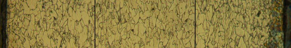

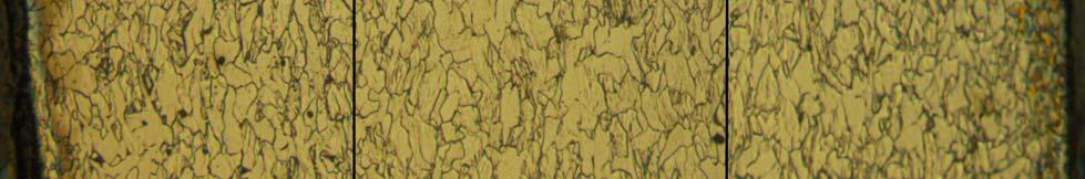
113 LIITE Mikrorakennekuvat Kuviin yhdistetty poikkileikkauksen molemmat reunat ja pala keskeltä a_x


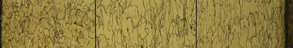

114 LIITE Mikrorakennekuvat a_y


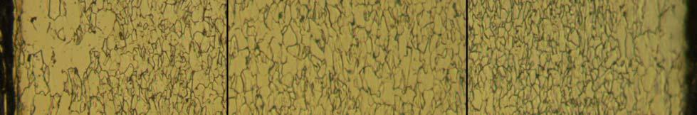
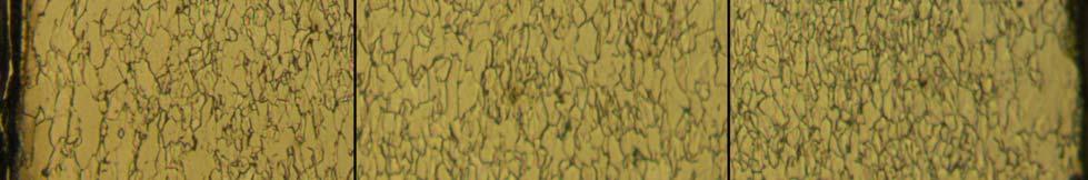
115 LIITE Mikrorakennekuvat d_x


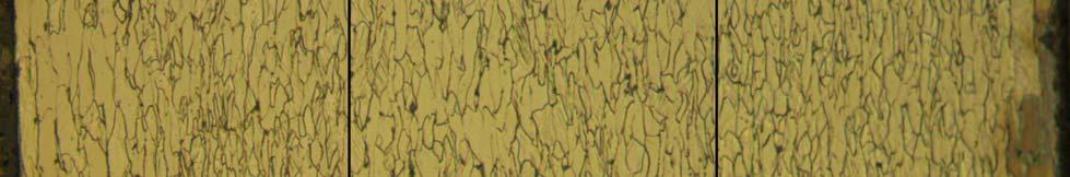

116 LIITE Mikrorakennekuvat d_y


117 LIITE Mikrorakennekuvat k_x


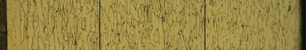

118 LIITE Mikrorakennekuvat k_y

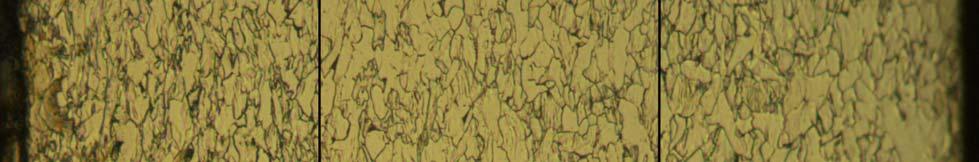

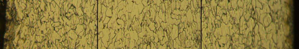
119 LIITE Mikrorakennekuvat n_x

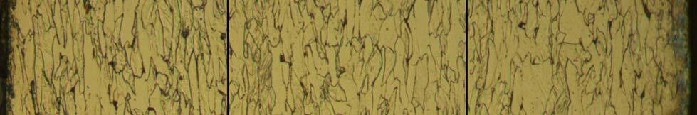
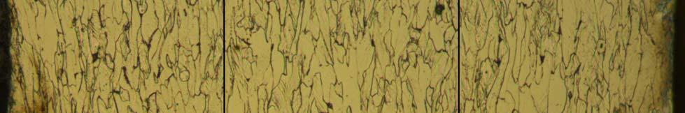

120 LIITE Mikrorakennekuvat n_y

121 LIITE Mikrorakenteisten metallituotteiden joustava valmistus, MIVA Ovako Wire Johtoryhmän kokous 4 VTT Espoo Jouko Virta VTT TECHNICAL RESEARCH CENTRE OF FINLAND Ovako Wire MIVA _ Luja hyvin vedettävä valssilanka Erikoislujat valssilangat ja langat tutkielma Vieraileva professori Leijun Li Utahin yliopistosta (Utah State University, Logan, Utah, USA) teki aiheesta kattavan kirjallisuustutkielman Tutkielmassa päädyttiin lopputulokseen, joka korostaa tavanomaisia valssaus ja langanvetotekniikoita sekä korkeahiilistä hiiliterästä 2 1
122 LIITE VTT TECHNICAL RESEARCH CENTRE OF FINLAND Ovako Wire MIVA _ Luja hyvin vedettävä valssilanka Luja ja sitkeä teräs Vain hienorakeinen rakenne (UFG) voi olla sekä lujaa että sitkeää Hieno alirakenne (ilman hienorakeisuutta voi olla lujaa, mutta ei sitkeää Superplastisuus on seuraus hienojen rakeiden pyörimisestä ja muodonmuutoksesta Raekoon hienoneminen on ainoa lujittumismekanismeista, joka alentaa iskusitkeyden transitiolämpötilaa 3 VTT TECHNICAL RESEARCH CENTRE OF FINLAND Ovako Wire MIVA _ Luja hyvin vedettävä valssilanka UFG terästä SPD ja ATP tekniikoilla Hienorakeinen UFG rakenne saadaan joko voimakkaalla kylmä/lämminmuokkauksella (SPD severe plastic deformation) tai kehittyneellä termomekaanisella käsittelyllä (ATP) SPD on pelkkää kylmämuokkausta kokonaismuokkausasteen ollessa useita satoja prosentteja (3 5) ATP sisältää muokkauksen (kuuma, lämmin, kylmä) lisäksi hallitun lämpötilasyklin ja jopa erillisen lämpökäsittelyn ATP:n etuna on perinteisten tekniikoiden käyttö: valssaus, takominen, langanveto ja pursotus 4 2
123 LIITE VTT TECHNICAL RESEARCH CENTRE OF FINLAND Ovako Wire MIVA _ Luja hyvin vedettävä valssilanka ATP tekniikka ATP pohjautuu muokkaukseen, Nb, Ti, V mikroseostukseen ja hallittuun jäähtymiseen: austeniitin dynaaminen rekristallisaatio kuumamuokkauksessa austeniitti ferriitti faasimuutos voimakkaan muodonmuutoksen aikaansaama ferriittimuutos SIF kuumamuokkaus austeniitti ferriittialueella, rakeen kasvun estäminen: nopea jäähdytys, mikroseostus ferriitin lämminmuokkaus ja rekristallisaatio / toipuminen 5 VTT TECHNICAL RESEARCH CENTRE OF FINLAND Ovako Wire MIVA _ Luja hyvin vedettävä valssilanka ATP tekniikka Dynaamisessa rekristallisaatiossa syntyvät rakeet ovat sitä hienojakoisempia mitä suurempi on muodonmuutosnopeus ja matalampi kuumamuokkauslämpötila Rakeet eivät kasva nopean jäähdytyksen ja mikroseostuksen ansiosta, ferriitin raekoko on 1 2 µm 6 3
124 LIITE VTT TECHNICAL RESEARCH CENTRE OF FINLAND Ovako Wire MIVA _ Luja hyvin vedettävä valssilanka TERMOMEKAANINEN KÄSITTELY Austeniitin voimakas muokkaus pienentää ferriitin raekokoa tiettyyn muokkausasteeseen asti Matala muokkauslämpötila johtaa pieneen raekokoon, nopea jäähtyminen siirtää ferriittialuetta matalampiin lämpötiloihin, seostus nostaa rekristallisoitumislämpötilaa sekä estää rakeenkasvua Ylieutektoisilla teräksillä muokkaus austeniitti sementiittialueella estää raerajakarbidien muodostumisen 7 VTT TECHNICAL RESEARCH CENTRE OF FINLAND Ovako Wire MIVA _ Luja hyvin vedettävä valssilanka TERMOMEKAANINEN KÄSITTELY MARTENSIITTIALUEELLA Erikoisena ATP tekniikkana on kylmämuokkaus Ms lämpötilassa ja muokkauksen jälkeinen hehkutus Ferriitin raekoko 0,18 µm ja tasaisesti ferriittiin jakautuneet nanokarbidierkaumat Kylmämuokkaus 50 % Ms lämpötilassa ja jälkihehkutus johtaa hienoon ferriittiseen rakenteeseen, jossa on hienoja nanoluokan karbidierkaumia Muokkauksessa syntynyt hienojakoinen dislokaatiosellirakenne muuttuu hehkutuksessa hienorakeiseksi ferriitiksi raekokoon 0,18 µm 8 4
125 LIITE VTT TECHNICAL RESEARCH CENTRE OF FINLAND Ovako Wire MIVA _ Luja hyvin vedettävä valssilanka ATP tekniikan vertailua Muodonmuutos on pienempi kuin SPD:ssä Raekoko ei ole yhtä hieno Hyödyntää tunnettuja jatkuvia teollisia massatuotantomenetelmiä Prosessointi ikkuna kapea ja vaativa kontrolloitavaksi 9 VTT TECHNICAL RESEARCH CENTRE OF FINLAND Ovako Wire MIVA _ Luja hyvin vedettävä valssilanka UFG terästä SPD ja ATP tekniikoilla Menetelmä Koostumus [%] Ferriitin raekoko [µm] Log. venymä Muokkauslämp ötila [ C] Jäähtyminen ja jälkihehkutus ECAP 0.08C 0.42Mn 0.18S 0,2 3,0 20 ilma ECAP 0.15C 1.06 Mn 0.25Si 0,8 4, C / 10 min, vesisammutus ATP 0.11C 1.45Mn 0.34Si 0.068Nb 2,0 5,0 2,2 3, ilma ATP 0.17C 1.32Mn 0.44Si 0.15Nb 2,1 2,3 700 vesi ATP 0.22C 0.21Si 0.74Mn 1,3 1, C / 120 min ATP 0.13C 0.37Mn 0.01Si 0,18 0,8 293 (Ms) 500 C / 30 min 10 5

126 LIITE VTT TECHNICAL RESEARCH CENTRE OF FINLAND Ovako Wire MIVA _ Luja hyvin vedettävä valssilanka Hienorakeinen UFG teräs termomekaanisesti Niukka ja matalahiilisillä teräksillä UFG rakenne ja hyvät mekaaniset ominaisuudet saadaan kylmä tai lämminvalssauksella Ms lämpötilassa ja hehkutuksella Ylieutektoidisilla teräksillä (>1 %C) UFG rakenne saadaan kylmämuokkaamalla (langanveto) Lähtörakenteen pitää olla homogeenista hienojakoista perliittiä ilman karbidiverkkoa. Kyseinen rakenne saadaan sopivalla jäähdytystekniikalla ja seostuksella, ja tarvittaessa termomekaanisesti takomalla tai pursottamalla. 11 VTT TECHNICAL RESEARCH CENTRE OF FINLAND Ovako Wire MIVA _ Luja ja hyvin vedettävä valssilanka YLIEUTEKTOIDISET HIILITERÄKSET Hiilipitoisuuden nostaminen on edullinen tapa lujittaa terästä: UHCS teräkset (ultrahigh carbon steel) 1,0 2,1 % C Suurin laboratorio olosuhteissa saavutettu vedetyn langan lujuus on 5000 MPa 12 6
127 LIITE VTT TECHNICAL RESEARCH CENTRE OF FINLAND Ovako Wire MIVA _ Luja hyvin vedettävä valssilanka Ylieutektoidisen langan lujuuden kasvu langanvedossa 13 VTT TECHNICAL RESEARCH CENTRE OF FINLAND Ovako Wire MIVA _ Luja hyvin vedettävä valssilanka YLIEUTEKTOIDISET HIILITERÄKSET Raerajakarbideja ei saa esiintyä, sementiittilamellien tulisi olla mahdollisimman ohuita Raerajakarbidiverkko voidaan estää nopealla jäähdyttämisellä valssauslämpötilasta (1,3 %C, C/s riittää hiilipitoisuudelle 1,1 %) seostuksella Si, Al ja Co termomekaanisella käsittelyllä 14 7
128 LIITE VTT TECHNICAL RESEARCH CENTRE OF FINLAND Ovako Wire MIVA _ Luja hyvin vedettävä valssilanka YLIEUTEKTOIDISET HIILITERÄKSET Seostus C pienentää perliitin lamellietäisyyksiä, vedettävyys paranee, delaminoitumisvaara pienenee, muokkauslujittumisnopeus kasvaa Mn hidastaa perlitoitumista Cr pienentää lamellietäisyyksiä, estää grafitoitumista Si ehkäisee karbidiverkkoa, lujittaa, nostaa perlitointilämpötilaa Al estää karbidiverkon muodostumista Co estää karbidiverkon muodostumista (1,3 %C) Ni vähentää delaminoitumista Seosaineiden haitat: valu vaikeutuu suotautuminen perlitoitumisaika pitenee oksidikerroksen poisto vaikeutuu 15 VTT TECHNICAL RESEARCH CENTRE OF FINLAND Ovako Wire MIVA _ Luja hyvin vedettävä valssilanka YLIEUTEKTOIDISET HIILITERÄKSET Esimerkki valmistuksesta Aihiot valetaan tavanomaisesti Parempi valurakenne saavutettaisiin nopealla jähmettymisellä (sulakerrostus) Valetut aihiot 1,0 1,45 %C kuumamuokataan Tangot austenitoidaan argonissa 1000 C:ssa, patentoidaan lyijykylvyssä 550 C / 3 min Kylmävedetään vaiheittain 15 % reduktioin nopeudella 8 m/min 16 8

129 LIITE VTT TECHNICAL RESEARCH CENTRE OF FINLAND Ovako Wire MIVA _ Luja hyvin vedettävä valssilanka YLIEUTEKTOIDISET HIILITERÄKSET UHC terästen mikrorakenne pursotettuna 17 VTT TECHNICAL RESEARCH CENTRE OF FINLAND Ovako Wire MIVA _ Luja hyvin vedettävä valssilanka Ylieutektoidinen teräslanka Esieutektoidinen sementiitti lujittaa perliittistä rakennetta. Ylieutektoidisen perliittisen hiiliteräksen lujuus kulkee selvästi ylempänä kuin eutektoidisen 18 9

130 LIITE VTT TECHNICAL RESEARCH CENTRE OF FINLAND Ovako Wire MIVA _ Luja hyvin vedettävä valssilanka Ylieutektoidinen teräslanka Voimakkaasti vedetty lanka sisältää ferriittilamelleja. Sementiitin hiili on liuennut yikyllästeisenä tai erkautunut dislokaatioihin. Ferriittilamellien paksuus on luokkaa 10 nm. 19 VTT TECHNICAL RESEARCH CENTRE OF FINLAND Ovako Wire MIVA _ Luja hyvin vedettävä valssilanka Ylieutektoidinen teräslanka Hehkutus palauttaa kylmämuokatun perliitin sitkeyden ja jättää jäljelle jonkin verran lujittumista. Hehkutuksessa perliitin sementiitti palloutuu ja ferriitti muuttuu hienorakeiseksi tasaaksiaaliseksi. Ferriitin ja sementiitin raekoko on <1 µm
131 LIITE VTT TECHNICAL RESEARCH CENTRE OF FINLAND Ovako Wire MIVA _ Luja hyvin vedettävä valssilanka SUOSITELLAAN LUJAN LANGAN KEHITTÄMISTÄ Käytettävä tekniikka on ylieutektoidisen hiiliteräksen termomekaaninen valssaus ja kylmäveto Teräs on ylieutektoidista hiiliterästä 1,3 % C seosaineina Co, Si ja Cr Hyvä vedettävyys taataan laadukkaalla perlitoinnilla valssilinjassa tai erillisessä patentoinnissa (hienolamellaarinen perliitti) Valssilinjalla perlitointi vaatii erityisjärjestelyjä, mutta erillisessä patentoinnissa jäähtymiseen tulee myös kiinnittää huomiota Kylmäveto useissa vaiheissa nanomittakaavaisen hienojakoisen mikrorakenteen aikaansaamiseksi 21 VTT TECHNICAL RESEARCH CENTRE OF FINLAND Ovako Wire MIVA _ Luja hyvin vedettävä valssilanka JATKOTOIMENPITEET Valssilangan jäähdytyksen kehittäminen Perlitoinnin laadun parantaminen Nopea ja tasainen jäähdytys Patentointimahdollisuuksien ja vaatimusten tutkiminen Jäähtymisen reunaehdot Menetelmät Simulointi: kokeellinen, tietokoneavusteinen 22 11
132 LIITE Mikrorakenteisten metallituotteiden joustava valmistus, MIVA Ovako Wire Johtoryhmän kokous 6 Ovako Wire Taalintehdas Jouko Virta ja Mika Siren Ovako Wire - MIVA Luja hyvin vedettävä valssilanka KIRJALLISUUSSELVITYS 'ERIKOISLUJAT VALSSILANGAT JA LANGAT' Professori Leijun Li Utahin yliopistosta laatima review-artikkeli Ultrahigh Strength Wire Rods and Wires Based on Severe Plastic Deformation (SPD) and Ultrafinegrained (UFG) Microstructure ilmestyy Materials Science and Technology -lehdessä kesäkuussa Käyttölupa artikkelin lähteistä otettuihin kuviin hankittu ja osin ostettu 1

 Jyrsittyihin pintoihin jäi näkyviin valupinnassa olleiden kuoppien pohjia Huonolaatuisin aihio halkaistiin: sisus ehjän näköistä 8.7.2010 4 Ovako Wire - MIVA Luja hyvin vedettävä")
133 LIITE Ovako Wire - MIVA Luja hyvin vedettävä valssilanka LUJAN LANGAN VALMISTUS YLIEUTEKTOIDISESTA HIILITERÄKSESTÄ Taalintehtaalla on tarkoitus valssata 5,5 mm:n valssilankaa koeaihioista Kolme valssausaihiota 125 x 125 mm valettiin (Inst.) Valut pehmeäksihehkutettiin 200 C/h lämpötilaan 1100 C, pito 4 h ja jäähtyminen uunin mukana lämpötilaan <200 C (Inst.) Jyrsintä mittaan 115 x 115 x n. 700 mm (Inst.) Jyrsittyihin pintoihin jäi näkyviin valupinnassa olleiden kuoppien pohjia Huonolaatuisin aihio halkaistiin: sisus ehjän näköistä Ovako Wire - MIVA Luja hyvin vedettävä valssilanka YLIEUTEKTOIDINEN HIILITERÄS Mikrorakenteessa ei saa olla karbidiverkkoa, perliitin ja muunkin mikrorakenteen tulee olla mahdollisimman hienojakoista ja epämetallisia sulkeumia on vältettävä Koostumuksen valintaperusteita: 1,6 % C (korkea hiili on lujuuden perusta, hiili lisää lujuutta ja lujittumista langanvedossa) 1,5 % Al (alumiini estää raerajakarbidien muodostumisen, nostaa A 1 -lämpötilaa) 1,3 % Cr (kromi estää grafitoitumista, pienentää lamellietäisyyksiä, lisää lujuutta ja lujittumista langanvedossa) 0,2 % Si (pii ehkäisee karbidiverkkoa ja liuoslujittaa) 0,3 % Mn (mangaani rikin ja fosforin sitomiseen, yhdessä kromin kanssa parantaa karkenevuutta) Epäpuhtausrajat: <0,015 % S, <0,020 % P, <0,001 % As, <0,0001 % Pb ja <0,004 % Sn (lujan langan tulee olla mahdollisimman puhdasta) Matala rikki on etu langanvedossa vähentäen katkeamista ja delaminoitumista: Tavanomainen rikkitaso 0,015-0,025 % takaa riittävän vetositkeyden. Lujilla langoilla tätä matalampi rikki antaa riittävän sitkeyden myös väännössä. 2
134 LIITE Ovako Wire - MIVA Luja hyvin vedettävä valssilanka YLIEUTEKTOIDISEN HIILITERÄKSEN TOTEUTUNUT KOOSTUMUS Seosaine C Tilattu (VTT) 1,45-1,75 Sulaanalyysi (Instituutti) 1,66 Kanaviston pala (Instituutti) 1,71 Kappaleanalyy sit (Ruukki) 1,68 Si (0,2) 0,64 0,69 0,71 Mn (0,3) 0,70 0,70 0,76 P <0,010 0,01 <0,01 0,017 S <0,020 0,01 <0,01 0,007 Al 1,35-1,75 1,36 1,36-1,8 1,8 Cr 1,10-1, ,37 Pb Sn <0,01 <0,01 <0,002 <0, Ovako Wire - MIVA Luja hyvin vedettävä valssilanka KUUMAPURISTUSTA VTT:SSA Valuista leikattuja palikoita 50 x 50 x 50 mm kuumapuristettiin Puristuslämpötila 1100 n.850 C Tavoite pinta-alareduktio % (50 x 50 mm 2 22,36 15,81 mm 2 ): luonnollinen venymä: ln(a 0 /A 1 ) = 1,61 2,30 2,00 1. venytys ln(a 0 /A 1 ) = 0,50 A 1 = 1516 mm 2 = 39 x 39 mm 1. tyssäys A 1 (1516) A 0 (2500); ln(a 1 /A 0 ) = 0,50 2. venytys ln(a 0 /A 1 ) = 0,50 A 1 = 1516 = 39 x 39 mm 2. tyssäys A 1 (1516) A 0 (2500); ln(a 1 /A 0 ) = 0,50 Luonnollinen venymä yhteensä 4 x 0,5 = 2,00 venytys-tyssäysohjelmalla: 50 x 50 x 50 mm 82 x 39 x 39 mm 50 x 50 x 50 mm 39 x 39 x 82 mm 50 x 50 x 50 mm Teelmän 115x115 mm valssauksessa valssilangaksi 5,5 mm: Pinta-alareduktio (A 0 -A 1 )/A 0 = 99,82 % Luonnollinen venymä ln(a 0 /A 1 ) = 6,322 3


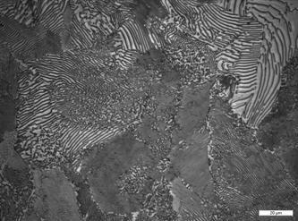

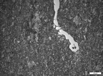
135 LIITE Ovako Wire - MIVA Luja hyvin vedettävä valssilanka KUUMAPURISTUSTA VTT:SSA Ovako Wire - MIVA Luja hyvin vedettävä valssilanka MIKRORAKENNE JA KOVUUS ENNEN JA JÄLKEEN KUUMAPURISTUKSEN 286 HV5: pehmeäksi hehkutettu valu 461 HV5: kuumamuokattu 2,00 4
 hidas jäähtyminen lämpötilaan 750 C nopeudella 1 C/min jäähtyminen")

136 LIITE Ovako Wire - MIVA Luja hyvin vedettävä valssilanka KUUMAPURISTETTUJEN JATKOKÄSITTELYT Sementiitin palloutus: austenitointi 20 min lämpötilassa 815 C (hieman A1:n yläpuolella) hidas jäähtyminen lämpötilaan 750 C nopeudella 1 C/min jäähtyminen vapaasti ilmassa Mikrorakennehaaveet: Perlitointi/patentointi: austenitointi 30 min lämpötilassa 860 C (reilusti A1:n yläpuolella) nopea jäähdytys lämpötilaan noin 575 C leijupatjaan pito 20 min lämpötilassa 575 C leijupatjassa jäähtyminen vapaasti ilmassa Ovako Wire - MIVA Luja hyvin vedettävä valssilanka YLIEUTEKTOIDISEN VALSSILAGAN VALSSAUS TAALINTEHTAALLA Aihiot 115 x 115 x n.700 mm liitetään Taalintehtaan 650-parin aihion eteen ja valssataan 5,5 mm:n langaksi Liitoshitsaus: valetun aihion kulmien pyöristys: näyteaihion särmät voidaan rälläköidä pyöreiksi viisteytys 30 hitsausta varten, keskelle voi jättää 2-3 mm navan hyvä esikuumennus aiemman kokemuksen mukaisesti hitsaustarkastelu seuraavissa kalvoissa Valssauslämpötilat ja reduktiot sekä langan jäähdytys valssilinjassa valssaus lievennetyllä 5,5 mm:n HC-ohjelmalla (?) karbidiverkolta vältytään, kun valssaus riittävän matalaan lämpötilaan (valssauslämpötila C) hidas jäähtyminen jäähdytyspedillä (valssilanka patentoitava erikseen) 5


137 LIITE Ovako Wire - MIVA Luja hyvin vedettävä valssilanka 650-VARSIA TAALINTEHTAALLA 650-parilla valssatuista aihioista, 650-aihion mitat? Varsilla pyöreät särmät, jolloin näyteaihion särmät voidaan rälläköidä pyöreiksi Polttoleikatut päätypinnat viisteytetään 30 hitsausta varten, keskelle voi jättää 2-3 mm navan Esikuumennus aiempien kokemusten mukaan Hitsaustarkastelu seuraavissa kalvoissa Ovako Wire - MIVA Luja hyvin vedettävä valssilanka HIILITERÄKSEN Ms- LÄMPÖTILA Ms-lämpötila: aihio <200 C, varsi C (arvaus) ons/thumb/c/cd/carbon_dependance_of_martensite.svg/265px- Carbon_dependance_of_martensite.svg.png&imgrefurl= dia.org/wiki/file:carbon_dependance_of_martensite.svg&usg= Oo4gtyxMZ6a 7- P168rGXKF6Mo7I=&h=208&w=265&sz=11&hl=fi&start=41&um=1&itbs=1&tbnid =kgmutvynrdsmbm:&tbnh=88&tbnw=112&prev=/images%3fq%3d%2522ma rtensite%2bstart%2522%26start%3d36%26m%3d1%26hl%3dfi%26sa%3dn% 26rls%3DGGLG,GGLG: ,GGLG:fi%26ndsp%3D18%26tbs%3Disch:1 6
138 LIITE UHCS-hitsaus SFS-EN : Metallisten materiaalien hitsaussuositukset. Osa 2: Ferriittisten terästen kaarihitsaus Ylihiilinen teräs ei mahdu SFS-EN liite C kaavoihin Esikuumennustarpeen määrittäminen vetyhalkeilun välttämiseksi Tapa A graafinen: hiiliekvivalentti 0.3 < CE < 0.7 CE UHCS = 2.08 Tapa B laskennallinen: hiiliekvivalentti 0.2 < CET < 0.75 CET UHCS = UHCS-hitsaus Musta-ruostumaton eripariliitosten hitsauksessa käytetään yleisesti Schaeffler-diagrammia (ja sen modifioituja versioita) Ylihiilinen teräs ei mahdu myöskään näihinkään diagrammeihin Laskentakaavoista ei apua Hitsausohjeet määritettävä kokeellisesti Yleisiä ohjeita kuitenkin valuraudan ja -terästen pohjalta: Käytetään mieluummin matalahiilistä vartta Ei haeta lisäongelmia korkeahiilisellä Esikuumenna aina kun se on mahdollista Mitä korkeampi esikuumennus, sitä parempi (~ C?) Käytä pehmeää austeniittista tai nikkelipohjaista lisäainetta Esim. E L R 3 2 ( ) tai E L R 3 2 ( ) (puikot) Tai vastaava MAG-umpi- tai rutiilitäytelanka (ns. asentolanka) 7
139 LIITE UHCS-hitsaus Lisäainemäärä: hyvin karkea laskelma ( suuruusluokka ) Railo: esim. 60 V-railo (eli ) V railo = 1900 cm 3 /m (teoreettinen) Hitsiainemäärä ~ 15 kg/m Esim. 3.2 tai 4.0 mm tai puikko: hitsiainetta n. 0.6 kg/1 kg puikkoja Puikkomenekki ~ 25 kg/m; railon kokonaispituus (4x0,5)x115=230 mm; puikkoja ~ 6 kg(?) Ilmarako ~ 2 mm Juuripinta ~ 2 3 mm/sivu Hitsausjärjestys suoruusvaatimusten mukaan (vetelyt ja taipumiset, varsi ja näyte linjaan) Ovako Wire - MIVA Luja hyvin vedettävä valssilanka VALSSILANGAN TUTKIMINEN Valssilangasta tutkitaan mikrorakenne mitataan mekaaniset ominaisuudet, Re, Rm, A, Z, Valssilanka kylmämuokataan ja tutkitaan mahdollisuuksien mukaan vedettävyys ja muokkauslujittuminen kylmämuokatusta mikrorakenne ja mekaaniset ominaisuudet 8


140 LIITE VTT luo teknologiasta liiketoimintaa 9

141 LIITE 6.1 Materiaalitekniikan laitos JUHO RAJAMÄKI ECAP-PROSESSOITUJEN METALLIEN RAKENNNE JA MEKAANISET OMINAISUUDET. STRUCTURE AND MECHANICAL PROPERTIES OF ECAP PROCESSED METALS. Kandidaatin työ Tarkastaja: Yliassistentti Mikko Hokka
142 LIITE 6.1 I TIIVISTELMÄ TAMPEREEN TEKNILLINEN YLIOPISTO Materiaalitekniikan koulutusohjelma RAJAMÄKI, JUHO: ECAP-prosessoitujen metallien rakenne ja mekaaniset ominaisuudet. Kandidaatin työ, 27 sivua Huhtikuussa 2009 Pääaine: Metallimateriaalit Työn tarkastaja: Yliassistentti Mikko Hokka Avainsanat: ECAP, ultra-hieno kiderakenne, lämpötilasta ja myötönopeudesta riippuva käyttäytyminen Tämä työ on selvitys kirjallisuudessa julkaistusta aineistosta equal-channel angular pressing-prosessilla (ECAP) valmistetuista ultra-hienorakeisista (UHR) metalleista. ECAP-prosessointi on teollisesti lupaava menetelmä, koska sillä voidaan hienontaa metallien raekoko alle 1 µm ilman ylimääräisiä seosaineita. Tarkoitus oli selvittää millaisia mekaanisia ominaisuuksia ECAP-prosessoimalla metalleja on saavutettu, ja erityisesti miten lämpötila ja myötönopeus vaikuttavat näihin ominaisuuksiin. Kirjallisuusselvityksen tuloksena voidaan todeta, että UHR metallit ovat yleisesti erittäin lujia, mutta näiden murtositkeys on alhainen vedossa ja ne muokkauslujittuvat erittäin vähän. Erilaiset termomekaaniset ja mekaaniset käsittelyt voivat parantaa UHR metallien sitkeyttä, ilman että lujuus laskee merkittävästi. UHR metallit käyttäytyvät sitkeämmin sekä lujemmin, kun niitä kuormitetaan korkeilla myötönopeuksilla tai alle huoneen lämpötilassa. Riittävän matalilla myötönopeuksilla ja korkeissa lämpötiloissa useat UHR metallit käyttäytyvät superplastisesti, eli ovat pehmeitä ja erittäin hyvin muokkautuvia. UHR metalleissa tapahtuu toipumista ja rekristallaatio huomattavasti alhaisemmissa lämpötiloissa kuin tavallisilla menetelmillä valmistetuissa metalleissa, mikäli näitä ei ole erityisesti stabiloitu. UHR metallien myötönopeusherkkyys on suurempi kuin suurirakeiten metallien, mikäli näiden kiderakenne on pintakeskeinen kuutiollinen (PKK), ja pienempi, mikäli kiderakenne on tilakeskeinen kuutiollinen (TKK). Suurin osa julkaistuista tutkimuksista käsitteli PKK ja TKK metalleja, joten heksagonaalisen tiivispakkaus rakenteen UHR metalleista voidaan arvioida vain mekaanisten ominaisuuksien peruspiirteitä kohtuullisen luotettavasti. Näiden mekaanisten ominaisuuksien lämpötila- ja myötönopeusriippuvuuksista ei voida tehdä varmoja johtopäätöksiä.
143 LIITE 6.1 II ALKUSANAT Tämä on Tampereen teknilliselle yliopistolle suoritettava tekniikan kandidaatin opinnäytetyö. Se on laadittu materiaali- ja koneinsinööreille suunnatuksi selvitykseksi ultrahienorakeisten metallien mekaanisista ominaisuuksista. Työ on tehty ensimmäinen kirjallinen selvitykseni, joten tarvitsin sen tekemiseen runsaasti apua. Suurimman osan ohjeista sain ohjaajaltani Mikko Hokalta ja hän auttoi minua asiakysymysten jäsentelyssä sekä työssä esittämieni ajatusten selkeyttämisessä. Kiitos kuuluu myös vanhemmilleni Erkki Rajamäelle ja Leena Rajamäelle, heidän kärsivällisyydestään ja neuvoistaan. Lopuksi kiitän kihlattuani Anne-Mari Honkavaaraa loputtomasta kärsivällisyydestä, tuesta ja oikeinkirjoitusohjeista.
144 LIITE Sisällys 1. Johdanto ECAP-menetelmä ECAP-prosessoinnin aikaansaama mikrorakenne Muodonmuutosmekanismit UHR metalleissa UHR metallien mekaaniset ominaisuudet Lujuus, kovuus ja sitkeys Lämpötilan vaikutus mekaanisiin ominaisuuksiin Myötönopeuden vaikutus mekaanisiin ominaisuuksiin UHR metallien syklinen käyttäytyminen Yhteenveto... 22
145 LIITE Lyhenteet ja merkinnät CP ECAP PKK TKK UHR φ ψ σ 0,2 σ 0 α d σ α M G b ρ wt-% γ` Commersial purity Equal-channel angular pressing Pintakeskeinen kuutiollinen rakenne Tilakeskeinen kuutiollinen rakenne Ultra-hienorakeinen ECAP-muotin kulma ECAP-muotin sisäkulman pyöristys Myötölujuus 0,2 % myötymän arvolla Hilakitka Hall-Petch yhtälön materiaalivakio Keskimääräinen raekoko Myötölujuus Taylorin yhtälön materiaalivakio Taylorin kerroin Leikkausmoduuli Burgersvektorin pituus Dislokaatiotiheys Painoprosenttia Alumiinin ja hopean välinen metastabiili faasi
146 LIITE Johdanto Nykyisin yritykset tarvitsevat jatkuvasti lujempia ja halvempia materiaaleja. Lujuuden kasvaessa materiaalin sitkeys tavallisesti vähenee, mikä vähentää lujien materiaalien käyttökohteita. Raekokoa pienentämällä voidaan parantaa metallien lujuutta ja samalla säilyttää parempi sitkeys kuin tavallisilla lujittamismenetelmillä [1,2]. Tämä on kasvattanut kiinnostusta ultra-hienorakeisia (UHR) metalleja kohtaan. UHR metalleiksi luetaan metallit joiden raekoko on välillä 0,1-1 µm, ja joiden mikrorakenne on tasaakselinen sekä kohtuullisen homogeeninen. Lisäksi suurimmassa osassa raerajoista täytyy tapahtua suuri orientaation muutos, eli yli 50 % raerajoista täytyy olla korkean kulman rajoja (high angle boundary) [2]. Perinteisesti raekokoa on pyritty pienentämään termomekaanisten käsittelyjen avulla. Tällaisilla menetelmillä saavutetut raekoot ovat pienimmillään luokkaa ~1-10 µm [3]. Termomekaanisen prosessointi täytyy suunnitella erikseen jokaiselle seokselle, ja mikäli raekoko halutaan hyvin pieneksi, metalleihin täytyy seostaa aineita, jotka tekevät niistä kalliimpia sekä vaikeammin kierrätettäviä. Lisäksi lämpökäsittelyillä on vaikeata valmistaa metalleja, joiden raekoko on sama kappaleen sisustassa ja pinnassa. Pieni raekoko voidaan saavuttaa vaihtoehtoisesti erilaisilla voimakkaaseen plastiseen muodonmuutokseen perustuvilla prosesseilla [2,3]. Nämä prosessit ovat alkaneet kiinnostaa kansainvälistä tiedeyhteisöä, koska niiden avulla voidaan valmistaa bulkki UHR tai jopa nanorakeisia metalleja [3] ilman termomekaaniseen käsittelyyn liittyviä ongelmia [2,4]. Equal-channel angular pressing (ECAP) on prosessointimenetelmä, jolla voidaan aikaansaada voimakas plastinen muodonmuutos. Siinä aihio puristetaan suurella mekaanisella voimalla kanavan läpi, joka sisältää jyrkän kulman. Kulkiessaan kulman läpi aihio muuttaa muotoaan, mutta säilyttää saman poikkipinta-alan, jolloin prosessi voidaan toistaa niin monta kertaa, että aihioon on saavutettu haluttu määrä plastista muodonmuutosta. ECAP-prosessi on erityisen kiinnostava, koska sama prosessi käy lähes jokaiselle metalliseokselle, sillä saadaan aikaiseksi homogeeninen UHR mikrorakenne ja se on mahdollista laajentaa teolliseen mittakaavaan sopivaksi [2]. Tässä työssä kootaan tieteellisistä julkaisuissa esitettyä tietoa UHR metallien mekaanisista ominaisuuksista, sekä lämpötilan ja myötönopeuden vaikutusista niihin. Pääpaino on ECAP-prosessilla valmistettujen UHR metallien mekaanisissa ominaisuuksissa. Työ kuuluu osakokonaisuutena projektiin, jonka tarkoituksena on tutkia, onko ECAPprosessi kehitettävissä teolliseen mittakaavaan sopivaksi, ja voidaanko sen avulla saavuttaa merkittävää kilpailuetua raaka-aine markkinoilla. Tämän työn tarkoitus on koota kirjallisuudessa esitettyä tietoa ECAP-prosessoiduista metalleista, ja siten auttaa ym-
147 LIITE märtämään menetelmän potentiaalista arvoa sekä helpottaa näiden raaka-aineiden positioimista oikealle markkinasegmentille sopivaksi.

148 LIITE ECAP-menetelmä ECAP-prosessointi on tapa valmistaa ultra-hienorakeisia metalleja, jotka eivät sisällä huokosia ja ovat mikrorakenteeltaan homogeenisia. Tässä menetelmässä työstettävä aihio puristetaan muotin läpi, jonka sisällä kaksi samankokoista tasapaksua kanavaa, jotka kohtaavat toisensa kulmassa φ. Kuva 1 esittää poikkileikkauksen yksinkertaisesta ECAP-muotista. Aihio puristetaan muotin läpi mekaanisen voiman avulla, jolloin se muokkautuu voimakkaasti. Kun aihio puristetaan muotin, jonka kulma φ on 90º, läpi aihioon kohdistuu ~1 mm/mm myötymää vastaava plastinen muodonmuutos [2,3,5]. Raekoko pienenee voimakkaan plastisen muodonmuutoksen seurauksena [6-8]. Kuva 1. ECAP-muotin poikkileikkaus Kulma φ sekä sisäkulman pyöristys ψ vaikuttavat aihioon kohdistuvan plastisen myötymän määrään. Jotkin metallit eivät kestä puristusta 90º kulman läpi, joten näille käytetään muotteja, joiden φ kulma on suurempi. ECAP-prosessin helpottamiseksi ja nopeuttamiseksi muottia voidaan lämmittää ja muotissa voi olla samaan aikaan useampia kulmia, jolloin yhdellä puristuskerralla saavutetaan suurempi myötymä. ECAP-muoteista on myös kehitetty erilaisia valssausteloilla toimivia jatkuvatoimisia malleja, jotta prosessia voitaisiin nopeuttaa ja kasvattaa teollisuuden tarpeisiin sopivaksi. Tarkempi selvitys erilaisista ECAP-prosessointi mahdollisuuksista löytyy esimerkiksi lähteestä [2]. ECAP-prosessointi voidaan yhdistää muihin lujittamismenetelmiin helposti. ECAPprosessointi voidaan suorittaa sellaisessa lämpötilassa, että rakenteeseen saadaan syntymään toivottuja erkaumia tai faasimuutoksia sekä mikrorakenteesta saadaan sellainen kuin halutaan. Prosessointi soveltuu suurimmalle osalle metalliseoksista, joten liuoslujittaminen on mahdollista. Lisäksi metalleihin jää prosessoinnin jälkeen jonkin verran sitkeyttä jäljelle, jolloin näitä voidaan lujittaa vielä kylmämuokkaamalla, mikäli se on
149 LIITE tarpeen. ECAP-prosessia voidaan käyttää myös erilaisten metallimatriisi komposiittien käsittelyyn [2]. ECAP-prosessoinnilla on monia etuja muihin voimakkaan plastisen muodonmuutoksen aikaansaaviin menetelmiin nähden. Sillä voidaan prosessoida materiaalia teollisessa mittakaavassa [2,9], eikä kappaleeseen pääse syntymään virheitä erilaisten tiivistysprosessien seurauksena [5]. Perinteisiin termomekaanisiin menetelmiin verrattuna ECAPprosessi on hyödyllinen, koska voimakas plastinen muodonmuutos mahdollistaa huomattavasti pienemmän raekoon saavuttamisen, eikä prosessia tarvitse suunnitella erikseen eri metalliseoksille [3]. Voimakkaalla plastisella muodonmuutoksella voidaan tuottaa metalleille erittäin houkuttelevia ominaisuuksia, ilman seostusta, mikä parantaa materiaalien kierrätettävyyttä [4] sekä tuottaa materiaalisäästöjä.
150 LIITE ECAP-prosessoinnin aikaansaama mikrorakenne ECAP-metallien mikrorakenne on ollut intensiivisen tutkimisen kohteena viimeisten vuosikymmenien aikana. Useita tutkimuksia on suoritettu erilliskiteillä sekä monikiteisillä metalleilla, ja ne kuvailevat kuinka metallin mikrorakenne muuttuu voimakkaan plastisen muodonmuutoksen seurauksena [10,11]. Keskimääräinen dislokaatiotiheys kasvaa ja raekoko pienenee puristuskertojen lisääntyessä, kunnes nämä saavuttavat kyllästetyn arvonsa. Saturaatiotila saavutetaan materiaalista riippuen, kun aihio puristetaan muotin läpi huoneen lämpötilassa 4-12 kertaa [12]. Mikäli aihiota käännetään 90 astetta samaan suuntaan pitkittäisen akselinsa ympäri ennen jokaista puristusta muotin läpi, kiderakenteesta tulee tasa-akselinen [3]. ECAP-prosessoitujen metallien mekaanista käyttäytymisen ymmärtämisen kannalta, näiden mikrorakenteen karakterisoiminen on välttämätöntä. UHR metallien mikrorakenteen erityispiirteitä ovat raerajoilla vallitseva jännitys sekä rakeiden orientaatiojakauma. Käytännön kannalta on välttämätöntä tietää, että raerajoilla vallitsee suuria mikrojännityksiä, silla ne vaikuttavat kaikkiin näiden metallien mekaanisiin ominaisuuksiin. Lisäksi prosessoinnista riippuen, raerajojen määrästä % ovat korkeankulman raerajoja [13]. Näiden lukumäärän tietäminen on tärkeätä, sillä dislokaatioiden liikkumismekanismit riippuvat raerajojen orientaatiosta. ECAP-prosessoitujen UHR metallien raekoko vaihtelee heterogeenisesti, siten että keskimääräinen raekoko on materiaalista riippuen tavallisesti välillä 0,07-1 µm [2,14,15]. Raekoon vaihtelu riippuu prosessoitavasta materiaalista siten, että suuren pinousvikaenergian omaavilla metalleilla mikrorakenne on homogeenisempi kuin alhaisen pinousvikaenergian metalleilla ECAP-prosessoinnin jälkeen. Monet muutkin tekijät, kuten erkaumat ja epäpuhtaudet vaikuttavat syntyvän rakenteen raekokojakaumaan, joten joissain metalliseoksissa rakenne saattaa olla hyvin kirjava, kun taas esimerkiksi puhtaan alumiinin rakenne on äärimmäisen homogeeninen [2]. Heterogeenisen rakenteen omaavien UHR metallien sisältämät rakeet voidaan jakaa kolmeen suuruusluokkaan, niiden sisältämän tekstuurin mukaan. Suurimmat rakeet ovat alle 1 µm kokoluokkaa ja pienimmät alle 100 nm [1,15]. Suurimmat rakeet sisältävät alirakeita ja omaavat korkean dislokaatiotiheyden. Keskikokoiset rakeet eivät sisällä alirakeita, mutta niissä on silti korkea dislokaatiotiheys. Pienimmät rakeet, jotka ovat nano kokoluokkaa, ovat lähes dislokaatiovapaita sisältä [1,15]. Rakenne sisältää suuria mikrojännityksiä ja raerajat ovat epätasapainossa [1,5,16], mikä tarkoittaa, että raerajoilla on enemmän dislokaatioita kuin vierekkäisten rakeiden yhteensopivuuden kannalta
151 LIITE olisi välttämätöntä. Suuret mikrojännitykset johtuvat korkeasta dislokaatiotiheydestä raerajojen tuntumassa ja rakeiden sisältämistä pienen kulman raerajoista [1]. Prosessointikertojen lisääntyessä suuren kulman rajojen määrä lisääntyy ja raerajat ohenevat ja samalla pienen kulman rajojen määrä vähenee [17-19]. Rakeiden sisällä olevat dislokaatiot pakkaantuvat sellien rajoille minimoidakseen jännitykseen sitoutuneen energian [12]. Riippumatta puristuskerroista, rakenteeseen jää kuitenkin suuri määrä pienen kulman rajoja [13], ja mikrotekstuuri koostuu eri leikkaus komponenteista [12].
152 LIITE Muodonmuutosmekanismit UHR metalleissa Aktiiviset muodonmuutosmekanismit riippuvat ainakin mikrorakenteesta, koostumuksesta, lämpötilasta ja myötönopeudesta. Tavallisesti metalleilla dominoiva muodonmuutosmekanismi huoneen lämpötilassa on dislokaatioiden liukuminen. Raekoon pienentyessä alle 1 µm, myös raerajojen liukumisella ja kiertymisellä alkaa olla merkitystä. ECAP-prosessoinnilla valmistetuilla metalleilla on hyvin pieni raekoko sekä erittäin korkea dislokaatiotiheys. Ultra-hienot rakeet muokkautuvat päätoimisesti samoilla mekanismeilla kuin suuremmat, joten näiden materiaalien kyky muokkauslujittua ei ole kovin suuri. Tämä merkitsee tavallisesti korkeaa lujuutta alhaista sitkeyttä vetokokeissa. UHR metallit eivät kuitenkaan ole hauraita, vaan ne murtuvat sitkeästi [20]. Vaikka UHR metallien dislokaatioiden generoimisnopeus on hyvin suuri, nämä eivät lujitu, sillä dynaaminen toipuminen on huomattavasti suurirakeisia metalleita voimakkaampaa [21]. Dislokaatiot törmäävät raerajoilla vastakkaismerkkisiin dislokaatioihin tai yhdistyvät näihin kiipeämällä ja annihiloituvat [22]. UHR metallia vedettäessä dislokaatiotiheys saavuttaa nopeasti kyllästetyn arvon, joten muokkauslujittuminen ei voi enää kompensoida poikkipinta-alan pienentymistä ja syntyy kurouma, joka johtaa lopulta murtumaan. Dislokaatiotiheyden kyllästetty arvo riippuu dislokaatioiden syntymisnopeuden ja palautumisnopeuden välisestä tasapainosta. Kyllästetty tiheys on suurempi matalissa lämpötiloissa sekä suuremmilla myötönopeuksilla kuormitetussa metallissa, joten sitkeys paranee näissä kuomitusolosuhteissa [2,12,23]. Kyllästetyn tiheyden arvo kasvaa, koska dynaaminen palautuminen vähenee lämpötilan laskiessa ja myötönopeuden kasvaessa [13,23]. Dislokaatioita lukitsevat seosaineet, kuten magnesium alumiinissa, nostavat metalliseoksen myötölujuutta, koska ne sitovat dislokaatioita paikoilleen ja siten haittaavat dynaamista toipumista, mikä nostaa dislokaatiotiheyden kyllästettyä arvoa [12]. Yleensä UHR metallit myötävät vetokokeessa melko vähän ja lisäksi muokkauslujittuvat myötämisen alkaessa tavallisesti erittäin vähän tai eivät ollenkaan, jonka jälkeen ne alkavat muokkauspehmenemään [2,4,23,24]. Tämä on seurausta UHR metallien mikrorakenteesta. Voimakkaalla plastisella muodonmuutoksella käsitellyissä metalleissa on suuri määrä sekä matalan- että korkeankulman rajoja, jotka vaikeuttavat dislokaatioiden liukumista [18]. Pienestä raekoosta johtuen raerajat toimivat sekä dislokaatiolähteinä että dislokaatiokaivoina ultra-hienoissa rakeissa [1,4,22,24], jolloin dislokaatioiden vapaa matka jää vääjäämättä alle raekoon. Suuren dislokaatioitiheyden sekä rakeiden sisältämien matalan kulman raerajojen vuoksi dislokaatioiden liikkeen keskimääräinen vapaa matka jää UHR metalleilla alle tavallisilla tavoilla tuotettujen metallien vapaan matkan. Esimerkiksi Al 3.3Mg 0.2Sc 0.2Zr seoksella, jonka keskimääräinen raekoko
153 LIITE oli 200 nm, alirakeiden koko oli 140 nm ja nämä sisälsivät sekalaisia dislokaatioryhmittymiä, joten dislokaatioiden keskimääräinen vapaa matka tässä materiaalissa oli luultavasti alle 100 nm. Dislokaatiotiheyden arvo saturoituu UHR metalleilla tavallisesti valmistusprosessin aikana tai nopeasti UHR metallin myötäessä, jonka vuoksi kyky muokkauslujittua jää alhaiseksi [12,25]. Alle 100 nm koon rakeissa on havaittu nanokaksosia, jotka syntyvät osittaisdislokaatioiden emissiosta raerajoilta [22,26]. Näitä kaksosia on löydetty keskisuure ja suuren pinousvikaenergian omaavilla metalleilla, kuten alumiinilla, nikkelillä ja kuparilla. Alhaisen pinousvikaenergian omaavilla metalleilla tällaisia mikrokaksosia voi esiintyä myös yli 100 nm rakeiden sisällä [26]. Mikrokaksoset voivat pysäyttää dislokaatioita keskelle raetta, jolloin rakeen dislokaatioiden varastointikapasiteetti kasvaa. Tämä nostaa materiaalin myötölujuutta ja sitkeyttä sekä mahdollisesti kykyä muokkauslujittua [12,26]. Aiheesta ei ole vielä kuitenkaan saatavilla riittävästi tutkimustuloksia, jotta vaikutusta voitaisiin arvioida luotettavasti. Raekoon pienentyessä rakeet voivat kuormitettaessa alkaa liukumaan ja kiertymään toistensa suhteen. Monissa tutkimuksissa on pyritty selvittämään eri ultrahienorakeisten metalliseosten superplastista käyttäytymistä [16,27,28]. Superplastisesta muokkauksesta pyritään kehittämään näiden materiaalien teollista muokkausta tukevaa tekniikkaa. Useissa tutkimuksissa [2,20,22,24,29,30] epäillään, että osa UHR metallien sitkeydestä koostuu raerajojen liukumisesta ja kiertymisestä. Tällaiset mekanismit riippuvat voimakkaasti lämpötilasta, ja tyypillisesti toimivat riittävän nopeasti vasta usean sadan Celsiusasteen lämpötiloissa aiheuttaakseen havaittavaa muodonmuutosta hienorakeisissa metalleissa. Kun metalleja kuormitetaan huoneenlämpötilassa, superplastiset muodonmuutosmekanismit vastaavan suurimmasta osasta metallin muodonmuutoksesta vasta raekoon laskiessa alle 10 nm. Raekoon ollessa ~100 nm luokkaa, rakeiden liikkumisella on kiistaton vaikutus metallien muodonmuutokseen huoneenlämpötilassa, mikäli myötönopeudet ovat erittäin pieniä [24]. Lämpötilan kasvaessa näiden mekanismien vaikutus kasvaa, siten että esimerkiksi Al 4Y 4Ni seoksen vetomurtositkeys myötönopeudella 10-3 s -1 kasvoi kymmenestä prosentista neljäänkymmeneen prosenttiin lämpötilan kasvaessa huoneenlämmöstä lämpötilaan 350 ºC [23]. Rakeiden kiertymistä ja liukumista ei kuitenkaan vielä ymmärretä riittävän hyvin, että tätä mekanismia pystyttäisiin hallitsemaan, ja monissa tutkimuksissa vain todetaan että rakeet muokkautuvat näillä mekanismeilla, ottamatta kantaa miksi ja miten tarkkaan ottaen tämä tapahtuu. Iso osa UHR metallien murtositkeydestä on tasamyötymän jälkeen tapahtuvaa kaulan kuroutumista. Ilman erityisiä käsittelyjä, ECAP-prosessoiduissa materiaaleissa on hyvin pieni tai ei ollenkaan tasamyötymää ennen muodonmuutoksen lokalisoitumista. Segal et al. tutkivat [20] ECAE prosessoidun [2] puhtaan Al0.5%Cu seoksen kuroutumista ja havaitsivat, että tämän metallin kuroutumisvaihe oli pidempi kuin saman materiaalin, jonka raekoko oli kasvatettu hehkuttamalla 12 µm: riin. Tähän arveltiin syyksi, että jännitys on riittävä mikromurtumien ydintämiseksi heti myötymän alkaessa lokalisoitua, mistä seurauksena on usean mikromurtuman homogeeninen ydintyminen ja kasvaminen. Esitetyn teorian mukaan yksittäinen mikromurtuma ei muodostu dominoivaksi, ku-
154 LIITE ten suurempirakeisissa metalleissa, jolloin murtuman kasvaminen lokalisoi jännityksen vasta myöhäisemmässä vaiheessa murtumisprosessia. Kyseisessä tutkimuksessa UHR Al0,5%Cu seoksen murtositkeydestä noin 90% oli kurouman myötämistä. Huomion arvoista on, että tutkimuksessa käytetty alumiiniseos sisälsi 0,1 µm erkaumia, jotka toimivat murtuman ydintäjinä. Mikäli näitä ei olisi, murtumisprosessi voisi olla toisenlainen. UHR metallien muodonmuutosmekanismeja ei vielä täysin ymmärretä. Erilaisia matemaattisia malleja muodonmuutosmekanismeista on paljon, mutta monia näistä ei ole tutkittu riittävästi, jotta niitä voitaisiin pitää luotettavina [1]. Esimerkiksi matemaattisen mallin mukaan, raerajat voivat säilyttää yhtenevyyden muokkautumalla ryhmissä, ja tämänlaiseen käyttäytymiseen viittaavia havaintoja on tehty UHR titaanilla [1], mutta aiheesta ei ole vielä varsinaista tutkimusta joka vahvistaisi syyksi juuri tällaisen mekanismin. Voimakkaan plastisen muodonmuutoksen avulla saavutetut ultra-hienot rakeet voivat muokkautua myös eri diffuusioprosessien avulla [1], sillä näihin rajoihin on sitoutunut paljon energiaa ja rakenteessa on paljon raerajaa, joten diffuusion ajava voima on riittävän suuri [16,31], jotta tämän kaltainen mekanismi voisi saada aikaan makroskooppisesti merkittävän muodonmuutoksen alhaisissa lämpötiloissa. Ainakin UHR metalleilla on tutkitusti huomattavasti pienempi raerajadiffuusion aktivaatioenergia kuin suurirakeisilla metalleilla [26], joten esimerkiksi Coble-viruminen voisi olla merkittävää alhaisissa homologisissa lämpötiloissa [1]. Diffuusiopohjaisista mekanismeista ei ole tehty vielä riittävästi tutkimuksia, että niiden vaikutuksia voitaisiin käsitellä luotettavasti, joten niiden merkityksen arviointi kokonaismuodonmuutoksen kannalta on vielä spekulointia.
155 LIITE UHR metallien mekaaniset ominaisuudet Tässä osiossa esitetään UHR metallien mekaaniset ominaisuudet peruspiirteittäin. Pääpaino on näiden metallien sitkeydellä, lujuudella sekä sillä, miten nämä ominaisuudet muuttuvat lämpötilan ja myötönopeuden muuttuessa. UHR metalleilla on tyypillisesti korkea lujuus ja kovuus sekä alhainen tasamyötymä verrattaessa vastaaviin suurirakeisiin metalleihin. Toisaalta tasamyötymän loppua seuraava kurouma kestää suhteessa pidempään kuin suurirakeisilla metalleilla [14,20]. Vaikka UHR metallien sitkeys on alhainen, ne murtuvat sitkeästi eivätkä hauraasti. ECAP-prosessilla valmistetut UHR metallit ovat myös sitkeämpiä kuin tavallisilla lujittamismenetelmillä samalle lujuustasolle prosessoidut metallit [2,32], joskaan näiden sitkeys ei ole riittävä tavallisiin rakenteellisiin sovelluksiin ilman erityisiä sitkeyttä lisääviä käsittelyjä. Raekoon pienentäminen laskee sitkeä-hauras siirtymä lämpötilaa teräksissä [31], mikä puolestaan lisää UHR teräksien käyttökohteita. Raekoko ei vaikuta metallien jäykkyyteen eli näiden materiaalien eri kimmomoduuleihin Lujuus, kovuus ja sitkeys Lujuutta voidaan arvioida raekoon perusteella, käyttämällä niin sanottua Hall-Petch yhtälöä. Se pitää paikkansa ainakin 0,2 µm raekokoon asti sekä PKK että TKK metalleilla [5,31], ja antoi luotettavan ennusteen Jia et al. [33] suorittamassa tutkimuksessa UHR titaanin, jonka raekoko oli noin 260 nm, lujuudeksi. Yhtälö 1 on niin sanottu Hall-Petch yhtälö ja siinä σ 0,2 on myötölujuus 0,2 % myötymän arvolla, σ 0 hilakitka, α materiaalivakio ja d keskimääräinen raekoko. Tässä yhtälössä α muuttuu dislokaatiotiheyden eli myötymän mukaan. Hall-Petch yhtälöä voidaan käyttää myös materiaalin kovuuden arvioimiseen, jolloin se antaa hyvän ennusteen ainakin teräksen kovuudeksi, aina 0,1 µm raekokoon asti [31]. σ ( MPa) = σ + αd 0, Lujuutta voidaan arvioida myös niin sanotun Taylorin yhtälön avulla [12,25]. Yhtälö 2 on Taylorin yhtälö ja se kuvaa dislokaatiotiheyden vaikutusta metallin lujuuteen. Siinä σ on myötölujuus, σ 0 hilakitka, α dislokaatiorakennetta kuvaava materiaalivakio, M Taylorin kerroin, G leikkausmoduuli, b burgesvektorin pituus ja ρ dislokaatiotiheys. α: n arvo muuttuu dislokaatiorakenteen mukaan. Metallin prosessointi vaikuttaa α arvoon [25], koska ECAP-prosessoinnilla saadaan aikaa erilaisia mikrorakenteita riippuen prosessointiparametreista [2]. (1)
156 LIITE σ ( MPa) = σ + αmgbρ (2) Hall-Petch yhtälö on lähinnä käyrän sovitus empiiriseen dataan, eikä se huomioi materiaalin muodonmuutosmekanismeja tai mikrorakennetta [1]. Mikäli UHR metallin mikrorakenne koostuu sekä erittäin pienistä rakeista että isommista, Hall-Petch yhtälö ei pysty ennustamaan metallin lujuutta kovin hyvin [2,15]. Taylorin yhtälö on puoliempiirinen yhtälö, joten se on sekä totuudenmukaisempi että kankeampi käyttää kuin Hall- Petch yhtälö. Se ei varsinaisesti huomioi materiaalin mikrorakennetta eikä sisäisiä jännityksiä, vaan ainoastaan kuvaa niitä sovitusparametrilla [15,25]. Molempien yhtälöiden käyttö UHR metalleiden lujuuden arvioimisessa on käytännöllistä, mikäli niiden tuloksia pidetään vain karkeina arvioina, sillä molemmat yhtälöt ovat pohjimmiltaan vain käyrän sovituksia mitattuun dataan. Tästä syystä yhtälöt eivät päde hyvin kaikille UHR metalleille, ja ne huomioivat myötönopeuden tai lämpötilan vaikutuksen vain, mikäli jokin yhtälön parametreista on riippuvainen näistä [24]. UHR metallien sitkeyden parantamiseen on kehitetty useita menetelmiä. ECAPprosessoinnin jälkeen sitkeyttä voidaan parantaa sopivassa lämpötilassa hehkuttamalla, syklisellä kuormittamisella tai näiden yhdistelmällä [35]. Näin saadaan aikaan mikrorakenne, joka koostuu sekä ultra-hienorakeisesta matriisista että tämän seassa olevista isommista rekristalloituneista rakeista [2,35]. Tällaisen rakenteen omaavan metallin lujuus on samaa suuruusluokkaa kuin heti ECAP-prosessoinnin jälkeen, mutta sen sitkeys on huomattavasti parempi [2]. 8 kertaa ECAP-muotin läpi puristetun, 1000 sykliä väsytetyn ja huoneen lämpötilassa viisi kuukautta pidetyn puhtaan kuparin (99,97 %) myötölujuus oli noin 350 MPa ja murtovenymä 22 % [35]. Puhtaan kupari myötölujuus hehkutettuna on noin 33 MPa ja murtovenymä 60 % [36]. Toinen tapa parantaa näiden UHR metallien sitkeyttä on lisätä prosessoinnissa tuotetun plastisen muodonmuutoksen määrää. Esimerkiksi kuparin sitkeys alkaa palautua ECAP-puristuskertojen lisääntyessä [13]. Tämän katsotaan johtuvan korkean kulman raerajojen osuuden kasvamisesta [13], mikä puolestaan edistää raerajojen liukumista ja kiertymistä [2,37]. Erittäin puhdas kupari (99,98 %) omaa 400 MPa murtolujuuden ja 15 % murtovenymän 25 ECAP-muotin läpipurituksen jälkeen, mikä vastaa noin 29 mm/mm myötymää [2,25]. Vertailun vuoksi kylmämuokatun puhtaan kuparin murtolujuus on 340 MPa ja murtovenymä 14 % [35]. Raekoon pienentäminen edelleen alle 100 nm kokoluokkaan parantaa sitkeyttä ja saattaa nostaa lujuutta, sillä se edistää samoja raerajojen kiertymis- ja liukumismekanismeja kuin myötymän lisääminen [2]. Kolmas tapa lisätä UHR metalliseoksien sitkeyttä on seostaa niihin aineita, jotka muodostavat sopivan lämpökäsittelyn aikana metastabiileja erkaumia. Nämä faasit lisäävät UHR metalien sitkeyttä, minkä uskotaan johtuvan siitä, että ne haittaavat leikkausnauhojen (shear-band) etenemistä [2]. ECAP-prosessoitua Al10,8wt-%Ag seosta hehkutettiin 373 K lämpötilassa, jotta tähän saatiin erkautettua metastabiilia γ` faasia. Tä-
157 LIITE män seoksen murtolujuus oli 270 MPa, ja sitä vastasi 14 % tasamyötymä ja 40 % murtovenymä [37]. UHR metallien sitkeyttä voidaan parantaa myös ECAP-prosessoinnin jälkeisellä kryogeenisessä lämpötilassa tapahtuvalla kylmämuokkauksella. Puhdas kupari (99,99 %) prosessoitiin eräässä tutkimuksessa [36] ECAP-menetelmällä, jonka jälkeen se kylmävedettiin ja valssattiin nestetypen lämpötilassa, jonka jälkeen materiaalin murtolujuus oli noin 500 MPa ja murtovenymä 11,8 %. Parantuneet mekaaniset ominaisuudet selitettiin sillä, että muokkaus nestetypen lämpötilassa lisäsi rakenteeseen korkean kulman raerajoja sekä muodosti kaksosia (deformation twin). UHR metallit kärsivät vedossa plastisesta epästabiilisuudesta alhaisilla myötymän arvoilla, koska näiden lujuus on korkea ja muokkauslujittuminen tavallisesti lähes olematonta. Tämä tarkoittaa että myötymä lokalisoituu helposti [23]. Myötymä lokalisoituu UHR metalleilla matalilla myötymillä, koska niiden muokkauslujittuminen on liian alhaista, jotta lujuuden kasvaminen pystyisi kompensoimaan poikkipinta-alan pienentymisen. Kun materiaaliin syntyy mikrokurouma, myötönopeus kuroutuneella alueella kasvaa, mikä lujittaa kuroumaa ja voi siten siirtää kuroutumisen toiseen paikkaan. Tämän vuoksi myötönopeusherkkyydellä voidaan katsoa olevan samanlainen vaikutus kurouman vastustamisessa kuin muokkauslujittumisellakin [23], millä on merkitystä etenkin superplastisessa muodonmuutoksessa. PKK rakenteiset UHR metallit vastustavat lokalisoitumista paremmin kuin TKK rakenteiset, koska näiden myötönopeusherkkyys on suurempi [38], mutta myös niillä havaitaan plastista epästabiilisuutta matalilla myötymillä [39]. Useilla TKK UHR metalleilla, kuten raudalla, tantaalilla ja volframilla, on havaittu plastista epästabiilisuutta suurilla myötönopeuksilla [38,40-43]. Jia et al. [33] tutkivat ECAP-prosessoitua puhdasta (CP) titaania ja havaitsivat, että myötymä lokalisoituu helposti tätä materiaalia vedettäessä. Tuloksesta voidaan päätellä, että ainakin jotkut HTP rakenteen omaavista UHR metalleista ovat plastisesti epästabiileja jo pienillä myötymillä. Pelkkä myötölujuuden arvo on huono suure kuvaamaan UHR metallien käyttäytymistä, sillä nämä sallivat vain erittäin pieniä myötölujuuden ylityksiä ja ovat herkkiä esim. korkeille lämpötiloille. Monilla UHR metalleilla ja seoksilla esiintyy joissain kuormitusolosuhteissa erittäin alhaista sitkeyttä ja muokkauspehmenemistä [22,30,44,45]. Jännitys-myötymä käyrä on huomattavasti parempi työkalu suunnittelussa kuin pelkkä myötölujuus, sillä se antaa realistisemman kuvan materiaalin käyttäytymisestä, mutta tämän lisäksi tarvitaan myös ymmärrystä näiden materiaalien tavallisista reaktioista eri kuormituksiin Lämpötilan vaikutus mekaanisiin ominaisuuksiin Yleisesti ottaen UHR metallit käyttäytyvät sekä sitkeämmin että ovat lujempia, kun näitä kuormitetaan alle huoneenlämpötiloissa [2,39,46]. Matalassa lämpötilassa muokattuun materiaaliin mahtuu enemmän dislokaatioita, sillä dislokaatiotiheyden kyllästetty arvo kasvaa lämpötilan laskiessa [12]. Dislokaatioiden annihiloituminen tapahtuu voi-
158 LIITE makkaammin korkeammissa lämpötiloissa, jolloin dynaaminen palautuminen voimistuu ja rakenteen kyllästetty dislokaatiotiheys laskee. Lujuus kasvaa lämpötilan laskiessa, koska termisen energian määrä vähenee ja muodonmuutoslujuuden (flow stress) terminen komponentti kasvaa. Mikäli lämpötila on riittävän korkea, rakenne palautuu erilaisten dynaamisten rekristallaatioprosessien avulla, mikä vähentävää dislokaatioiden liikettä rajoittavien esteiden määrä, eli laskee materiaalin lujuutta [16,23]. Dynaamiset rekristallaatioprosessit aiheuttavat UHR metalleissa myös muokkauspehmenemistä [22]. Samalla kun lujuus laskee lämpötilan kasvaessa, sitkeys paranee. Riittävän korkeissa lämpötiloissa ja riittävän alhaisilla myötönopeuksilla muokattaessa UHR metallit alkavat käyttäytyä superplastisesti, jolloin näiden sitkeys paranee huomattavasti ja lujuus laskee. Farrokh et al. [47] valmistivat puristuskoenäytteitä pyörittämällä metallipulvereita kuulamyllyssä ja tiivistämällä ne paineistetun sintrausprosessin avulla. Näin saatiin aikaiseksi nanokiteisiä alumiini- ja kupari-näytteitä, joiden myötö- ja muodonmuutoslujuutta tutkittiin eri lämpötiloissa sekä eri myötönopeuksilla. Lämpötilan vaikutus näiden metallien lujuusominaisuuksiin oli suurempi kvasi-staattisilla myötönopeuksilla kuin dynaamisissa kokeissa. Samassa tutkimuksessa havaittiin, että puristusmyötäminen sisälsi muokkauslujittumista aina huoneenlämpötilaan asti, mutta korkeammissa lämpötiloissa muokkauslujittumista ei tapahtunut lainkaan. Nämä tulokset eivät ole aivan suoraa yleistettävissä UHR metalleihin, koska testattujen materiaalien raekoko on niin pieni, että se mahdollistaa eri muokkautumismekanismeja. Lisäksi metallipulverien tiivistyksen yhteydessä on voinut syntyä erilaisia sulkeumia ja huokosia, jotka vääristävät tuloksia. ECAP-prosessoiduilla kuparilla, nikkelillä ja alumiinilla [16,22,46,48] on havaittu, että lämpötilan noustessa huoneenlämpötilan yläpuolelle, nämä metallit muokkauslujittuvat aluksi hyvin vähän, jonka jälkeen niiden lujuus pysyy samana tai laskee. Tämä trendi ei kuitenkaan päde kaikille UHR metalleille, sillä esimerkiksi Al 4Y 4Ni muokkauslujittui vielä 150 ºC lämpötilassa suoritetussa vetokokeessa [23]. Lämpötilan kasvaessa yli huoneen lämpötilan UHR metallien lujuus laskee. Lujuuden laskeminen on PKK UHR metalleilla huomattavasti voimakkaampaa kuin suurirakeisilla PKK metalleilla [16,23,22,48]. Samalla kun lujuus laskee, näiden metallien sitkeys paranee. UHR metallien korkean lämpötilan käyttäytymiseen liittyy myös muokkauspehmenemistä. Lähellä korkeinta lämpötilaa, jossa rakeet ovat stabiileja, ECAPprosessoidulla puhtaalla (99,99 %) kuparilla havaittiin pehmenemistä materiaalia kuormitettaessa [22]. Sama ilmiö on havaittu myös UHR puhtaalla alumiinilla ja muutamalla eri alumiiniseoksella [16,23,48]. Pehmeneminen liittyy läheisesti UHR metallien superplastiseen muodonmuutoskäyttäytymiseen korkeissa lämpötiloissa ja matalilla myötönopeuksilla. Tällaisissa olosuhteissa metalli pehmenee ja muuttuu sitkeämmäksi, minkä arvellaan johtuvan raekoon kasvamisesta, pienen kulman raerajojen vähenemisestä sekä raerajoilla sijaitsevien dislokaatioiden annihiloitumisesta kiipeämisen avulla [22]. Suuren dislokaatiotiheyden seurauksena ECAP-prosessilla valmistettuihin materiaaleihin on sitoutunut paljon myötymäenergiaa [5]. Wan et al. [49] osoittivat differentiaalisella pyyhkäisykalorimetrialla, että tämä energia vapautuu materiaalia lämmitettäessä.

159 LIITE Energia purkautuu, kun rakenteessa tapahtuu sisäisten jännitysten palautumista, rakeen kasvua tai rekristallaatio. Termisellä stabiilisuudella tarkoitetaan materiaalin kykyä säilyttää mikrorakennemuuttumattomana, eli vastustaa näitä palautumisprosesseja korotetussa lämpötilassa. Se on yksi tärkeimmistä UHR metallien käyttöä rajoittavista ominaisuuksista, koska rekristallaatio ja rakeenkasvu ovat suurimmat tekijät, jotka heikentävät näiden metallien ominaisuuksia korkeissa käyttölämpötiloissa, ja koska korkein käyttölämpötila on ainakin seostamattomilla UHR metalleilla hyvin alhainen. Kuvassa 2 on ECAP-prosessoidun puhtaan alumiinin mikrorakenne eri lämpötiloissa tapahtuneen tunnin pituisen hehkutuksen jälkeen. Kuvasta nähdään, että UHR alumiinin raekoko säilyy stabiilina aina 423 K lämpötilaan asti, mutta rakenne alkaa rekristalloitumaan lämpötilan ylittäessä tämän, ja jo 150 K lämpötilan nousu johtaa täydelliseen rekristalloitumiseen. Kuva 2. Puhtaan alumiinin mikrorakenne ECAP-prosessoinnin ja 1 h hehkutuksen jälkeen lämpötiloissa 423 K, 473 K, 523 K ja 573 K [2]. ECAP-prosessoidun alumiiniseoksen rakeenkasvun aktivaatioenergia on Geng et al. [16] mukaan huomattavasti alhaisempi kuin puhtaan alumiinin itsediffuusion aktivaatioenergia, sekä alhaisempi kuin alumiiniseoksen epäpuhtauksien diffuusion aktivaatioenergia. Tämä tarkoittaa, että atomien diffuusio on helpompaa, koska mikrorakenne sisältää ylimääräistä jännityskenttiin sitoutunutta energiaa [16]. Seurauksena alhaisesta rakeenkasvun aktivaatio energiasta ja suuresta määrästä raerajaa, rakeenkasvua ajava voima on korkea ja UHR metallien terminen stabiilisuus alhainen. Mekaaniset ominaisuudet alkavat heikentyä hyvin voimakkaasti lämpötilan noustessa, koska dislokaatiotiheys laskee ja raekoko kasvaa, jolloin molempien lujittava vaikutus vähenee. ECAPprosessoidulla Al1,5wt-%Mg seoksella havaittiin mikrorakenteen relaksoitumista jo huoneen lämpötilassa, kun näyteet puristettiin 0,2 mm/mm myötymään [48]. Kuormitusolosuhteet voivat edesauttaa mikrorakenteen palautumista, sillä UHR metalleissa tapahtuu myös plastisen myötymän aikaansaamaa rakeenkasvua [22,34].
160 LIITE Rakeenkasvua voidaan ehkäistä UHR metalleissa useilla eri tavoilla. UHR metallia voidaan stabiloida erkaumilla tai sopivalla seostuksella [32]. Hyvin pienet erkaumat ja seosaineet, jotka konsentroituvat raerajoille, parantavat termistä stabiilisuutta, koska ne hillitsevät rakeiden kasvua [50]. On kuitenkin syitä epäillä, että erkaumat ja seostus eivät ehkäise rakenteen relaksoitumista [48]. Hehkutusen rekristallisaatiolämpötilan alapuolella on havaittu myös parantavan termistä stabiilisuutta, koska tämä poistaa mikrojännityksiä ja tasapainottaa rakennetta [32]. UHR metallit, jotka eivät ole tyypiltään aaltoilevasti liukuvia (wavy slip), eli joiden pinousvikaenergia on alhainen, vaikuttavat kestävän korkeampia lämpötiloja [32]. Tämän tyyppisten metallien käyttäminen on suositeltavaa, mikäli UHR metallissa ei saa alkaa tapahtumaan rakeenkasvua käytön aikana. Metallin terminen stabiilisuus vaikuttaa korkean lämpötilan murtumismekanismeihin, sillä osittain tai kokonaan rekristalloitunut rakenne murtuu eri tavalla kuin ultrahienorakeinen. Segal et al. [20] tekemässä, murtumismekaniikkaa käsittelevässä tutkimuksessa Al0.5%Cu seos homogenisoitiin, erkautushehkutettiin ja prosessoitiin ECAE menetelmällä. Tutkimuksessa havaittiin, että tällä UHR metallilla on oma tyypillinen murtumisjälkensä, joka poikkeaa hieman hienorakeisten metallien murtumisesta. Samassa tutkimuksessa havaittiin, että 448 K lämpötilassa tunnin ajan hehkutettu UHR Al0.5%Cu seos murtui samalla tavalla kuin hehkuttamaton. Kyseisessä metallissa ei tapahdu rakeenkasvua vielä hehkutuslämpötilassa, mutta hehkutus poistaa kuitenkin mikrojännityksiä, eli voidaan päätellä että toipumishehkutuksella ei ole ratkaisevaa vaikutusta murtumismekanismeihin Myötönopeuden vaikutus mekaanisiin ominaisuuksiin UHR metallit käyttäytyvät yleisesti sekä lujemmin että sitkeämmin, kun niitä kuormitetaan suuremmilla myötönopeuksilla [2,24]. Dislokaatioiden generoitumisnopeus kilpailee dynaamisen palautumisen kanssa, ja kun nämä ovat tasapainossa, ei muokkauslujittumista enää tapahdu [21]. Mikäli dislokaatioiden generoituminen lisääntyy myötönopeuden kasvaessa, muokkauslujittuminen voimistuu ja sitkeys paranee, sillä muokkauslujittuminen viivyttää kurouman syntymistä, joka on metalleilla tavallisin murtumaan johtava syy [24]. Tällainen teoria selittäisi UHR metallien käyttäytymisen kohtuullisen hyvin. Lujuuden kasvaminen myötönopeuden kasvaessa voidaan selittää samalla tavalla kuin suurirakeisilla metalleilla, eli termisen aktivaation vähentymisen avulla [51]. Suuremmilla myötönopeuksilla termisestä energiasta ei saada yhtä paljon hyötyä, joten tarvitaan enemmän ulkoista työtä metallin muokkaamiseen, mikä näkyy lujuuden kasvamisena. Alhaisilla myötönopeuksilla lujuus ei kuitenkaan kasva täysin lineaarisesti suhteessa myötönopeuden logaritmiin. Epälineaarisuus johtuu raerajojen liukuminen ja kiertyminen sekä muista hitaasti aktivoituvista prosesseista, jotka tyypillisesti nostavat sitkeyttä ja laskevat lujuutta alhaisilla myötönopeuksilla [24]. Myötönopeusherkkyys kuvaa lujuuden muutosta myötönopeuden muuttuessa. Materiaali, jolla on suuri myötönopeusherkkyys, vastustaa myötönopeuden kasvamista voi-
161 LIITE makkaasti, jolloin sen lujuus kasvaa huomattavasti myötönopeuden lisääntyessä. Yhtälö 3 on myötönopeusherkkyyden suhteellinen määritelmä [24]. UHR metallien myötönopeusherkkyys riippuu voimakkaasti kiderakenteesta. PKK rakenteen omaavilla UHR metalleilla on isorakeisiin vastineisiinsa verrattuna korkeampi myötönopeusherkkyys [38,52,53]. Kuva 3a esittää PKK metallien myötönopeusherkkyyden riippuvuutta raekoosta. TKK rakenteen UHR metalleilla myötönopeusherkkyys puolestaan pienenee raekoon pienentyessä, mikä on esitetty kuvassa 3b. Näillä TKK rakenteisilla UHR metalleilla on pieni myötönopeusherkkyyden arvo verrattuna isorakeisiin vastineisiin [38,40]. Yang et al. [7] havaitsivat, että AZ31B magnesiumseoksen myötönopeusherkkyys kasvaa, kun sen raekoko hienonnetaan ABRC (alternate biaxial revese corrugation) prosessin [54] avulla luokkaan ~1 µm. Toisaalta Jia et al. [33] tutkivat puhdasta (CP) ECAP-prosessoitua titaania ja havaitsivat, että sillä oli alempi myötönopeusherkkyys kuin suurirakeisella titaanilla. Heksagonaalisen tiivispakkauksellisen rakenteen UHR metalleista ei ole kuitenkaan saatavilla riittävästi tutkimustuloksia, jotta näiden myötönopeusherkkyydestä pystyttäisiin tekemään luotettavia arvioita. logσ m = log & ε ε, T (3) Kuva 3. Myötönopeusherkkyyden riippuvuus raekoosta a) PKK metalleilla [53] ja b) TKK metalleilla [38]. Wei et al. [38] sekä Kapoor et al. [48] esittävät, että PKK metallien myötönopeusherkkyyden kasvaminen raekoon pienentyessä johtuu aktivaatiotilavuuden pienentymisestä. Aktivaatiotilavuus kuvaa dislokaatioiden keskimäärin liikkumaa matkaa, ennen esteeseen törmäämistä ja pysähtymistä, joten se vaikuttaa suoraan myötönopeuden riippuvuuteen ulkoisesta jännityksestä. Wei et al. [48] mittasivat sekä vertailivat suurirakeisten sekä UHR metallien aktivaatiotilavuuksien arvoja ja havaitsivat, että UHR me-
162 LIITE talleilla on selkeästi pienempi aktivaatiotilavuus. Esteet, jotka rajoittavat dislokaatioiden liikettä pienentävät aktivaatiotilavuutta. Molemmissa aktivaatiotilavuuden pienentymistä selittävistä tutkimuksista uskottiin, että rearajat haittaavat dislokaatioiden liikettä, ja siten aiheuttavan aktivaatiotilavuuden pienentymisen [38,48], mutta tätä ei pystytty todistamaan. Luultavimmin raerajojen luonne muuttuu siten, että ne alkavat emittoida dislokaatioita, mikä tekee näistä termisesti aktivoituvia esteitä [24,38,53]. Voimakkaaseen plastiseen muodonmuutokseen perustuva valmistusprosessi lisää raerajojen määrä ja dislokaatiotiheyttä, samalla kun se pienentää raekokoa. Aktivaatiotilavuus laskee, koska PKK metalleissa suurimmat esteet ovat raerajat sekä metsädislokaatiot [38,48,53]. Myötönopeuden kasvattaminen vaikuttaa siis samalla tavalla PKK rakenteisiin UHR metalleihin kuin isompirakeisiin vastineisiin, mutta riittävän pienirakeisten metallien raerajat alkavat haitata dislokaatioden liikettä samalla tavoin kuin metsädislokaatiot, jolloin metallin lujuus riippuu voimakkaammin termisestä energiasta [38,48]. TKK rakenteen UHR metallien suurin terminen este on Peierlsin hilakitka [38]. Dislokaatiot eivät voi ylittää raerajoja termisen energian avulla, joten raerajat muodostavat atermisen esteen dislokaatioiden liikkeelle. Tämä poikkeaa PKK UHR metallien käyttäytymisestä, joissa raerajat toimivat luultavasti termisenä esteenä [24,38,53]. Raekoon pienentyessä atermisten esteiden määrä kasvaa suhteessa termisiin esteisiin, sillä raerajan määrä metallissa lisääntyy, mutta hilakitka pysyy jokseenkin vakiona. Dislokaatioiden liikkumiseen tarvittava kokonaisenergia kasvaa, koska lujuuden aterminen komponentti voimistuu raekoon pienentyessä. Lujuuden terminen komponentti ei kasva, joten sen osuus pienenee suhteessa kokonaisenergiaan. Siten termisen energian vaikutus dislokaatioiden liikkumisnopeuteen pienenee, kun raekoko pienenee. Matalilla myötönopeuksilla, myötönopeuden muuttaminen vaikuttaa ainoastaan termisen aktivaation määrään, jolloin lujuuden ja myötönopeuden suhde riippuu tärkeimmästä termisesti aktivoidusta prosessista. Pienirakeisilla TKK metalleilla, tärkeimmän termisesti aktivoidun prosessin vaikutus kokonaislujuuteen on pieni, jolloin myös myötönopeusherkkyys on pienempi kuin suurempirakeisilla metalleilla [38,40]. ECAP-prosessoidun puhtaan (99,6 %) alumiinin murtositkeys laski myötönopeuden pienentyessä, UHR metalleille tyypillisellä tavalla, mutta kasvoi huomattavasti myötönopeuden laskiessa arvosta 10-3 s -1 arvoon 10-4 s -1. Myötönopeuden pienentyessä edelleen alle 10-4 s -1, murtositkeys jatkoi kasvamistaan. Tämän uskottaan johtuvan eri muodonmuutosmekanismien aktivoitumisesta. Pienemmillä myötönopeuksilla rakeiden kiertyminen ja raerajojen liukuminen sekä muut diffuusiopohjaiset mekanismit ja rakenteen relaksoituminen, vaikuttavat myötämiseen enemmän. Hitaat mekanismit voivat olla estyneitä tai liian hitaita aiheuttaakseen havaittavaa eroa suuremmilla myötönopeuden arvoilla, mutta ne lisäävät sitkeyttä, mikäli kuormitusolosuhteet sallivat sen [24]. PKK rakenteen UHR metallien myötönopeusherkkyys kasvaa tavallisesti lämpötilan mukana [22,23,38,48]. Lämpötilan vaikutus myötönopeusherkkyyteen ei ole täysin lineaarinen, koska näiden myötönopeusherkkyys on monimutkainen, useasta eri ilmiöstä koostuva ominaisuus. TKK metalleilla myötönopeusherkkyys pienenee lämpötilan kasvaessa, kun absoluuttinen lämpötila on lähellä huoneen lämpötilaa [38]. Korkeammissa
163 LIITE lämpötiloissa myötönopeusherkkyys alkaa kasvaa samalla tavalla kuin PKK UHR metalleilla [38]. Kuva 4 esittää kahden eri alumiiniseoksen myötönopeusherkkyyden riippuvuutta lämpötilasta. Kuva 4. Kahden eri alumiini seoksen myötönopeusherkkyyden riippuvuus lämpötilasta [23]. Mishra et al. [53] havaitsivat myötönopeudella 2500 s -1 testatuissa, 0,3 mm/mm myötymään puristetussa puhtaassa UHR kuparissa dynaamista rekristallisaatiota [53]. Tämä johtuu adiabaattisesta lämpenemisestä, eli metallien lämpenemisestä muokkauksen seurauksena. Samassa tutkimuksessa dynaaminen rekristalloituminen todettiin myös hatun muotoisilla veto Hopkinson Split Bar näytteillä ja Taylorin iskukoe-näytteillä. Mishra et al. [53] laskivat, että puristusnäytteissä 2500 s -1 myötönopeus ja 0,3 mm/mm myötymä saivat aikaan ~60 K lämpötilan nousun, mikä oli riittävä aiheuttamaan rekristallaatioita ECAP-prosessoidussa kuparissa. Adiabaattinen lämpeneminen riippuu voimakkaasti materiaalin lämmönjohtavuudesta, ominaislämpökapasiteetista sekä kuormitusolosuhteista. UHR metallit myötävät vetokuorman alla tavallisesti hyvin vähän ennen murtumista, joten adiabaattinen lämpeneminen aiheuttaa rekristalloitumista tällöin lähinnä kurouman alueelle, mikäli myötönopeus on riittävän suuri. UHR metallit ovat termisesti epästabiileja [2,53], joten ne ovat alttiita dynaamiselle rekristalloitumiselle puristettaessa UHR metallien syklinen käyttäytyminen Väsymismurtuman syntyminen voidaan jakaa murtuman ydintymiseen ja sen etenemiseen. Lujat materiaalit vastustavat paremmin murtuman syntymistä, kun taas sitkeät materiaalit kestävät paremmin murtuman etenemistä. UHR metallit kestävät luontaisesti paremmin murtuman syntymistä kuin sen etenemistä korkean lujuutensa ja alhaisen sitkeytensä vuoksi. Näillä materiaaleilla on mahdollista saavuttaa korkea lujuus sekä paremmat sitkeysominaisuudet kuin tavallisilla lujittamismenetelmillä, joten UHR metallit vaikuttavat lupaavilta materiaaleilta poikkeuksellisia väsymisominaisuuksia vaativiin sovelluksiin [2].
164 LIITE UHR metalleilla on parempi pitkäkestoisen väsytyksen väsymislujuus (high cycle fatique) yksinkertaisissa väsytyskokeissa suurempirakeisiin metalleihin verrattuna [32,44,55]. Pitkäkestoisen väsytyksen väsymislujuuden on todettu seuraavan Hall-Petch yhtälöä [2], joten esimerkiksi ECAP-prosessoinnilla voidaan parantaa tätä osaa metallien väsymisestä huomattavasti. Jännityskontrolloiduissa testeissä on osoitettu, että esimerkiksi puhtaan (CP) titaanin sietoraja 10 7 syklin jälkeen on voitu nostaa 50 % ECAPprosessoinnin ja kylmävedon avulla [55]. UHR metalleilla tehdyissä myötymäkontrolloiduissa väsytyskokeissa havaitaan syklistä pehmenemistä, rakeen kasvua ja myötymän lokalisoitumista, mitkä johtavat alhaiseen väsymisikään [2]. Väsymisikä saattaa olla UHR metalleilla jopa alhaisempi kuin tavallisen raekoon metalleilla, minkä katsotaan johtuvan UHR rakenteen alhaisesta termisestä ja mekaanisesta stabiilisuudesta sekä rakenteen voimakkaasta taipumuksesta palautumiseen [2]. Tämä ilmiö havaitaan voimakkaampana, kun plastisen myötymäamplitudin arvoa kasvatetaan. UHR metallin sisältämä mikrotekstuuri vaikuttaa sykliseen pehmenemiseen siten, että tasa-akselinen rakenne on tavallisesti stabiilimpi kuin orientoitunut tai lamellimainen rakenne [2]. UHR metallien väsymislujuutta voidaan räätälöidä käyttötarkoitukseen sopivaksi joko parantamalla niiden sitkeyttä aikaisemmassa luvussa esitetyillä tavoilla tai parantamalla metallin myötölujuutta kylmämuokkauksen avulla. Esimerkiksi sopivalla jälkihehkutuksella voidaan nostaa kuparin lyhytkestoinen väsymisikä ~5-10 kertaiseksi [2]. Oikein suoritetulla erkaumakarkaisulla voidaan parantaa UHR metallien väsyttävän kuormituksen alaista käyttöikää, sillä erkaumat lisäävät sitkeyttä samalla kuin ne hidastavat rakenteen palautumista. Lisäksi oikein suunniteltu erkautushehkutus vähentää rakenteesta jäännösjännityksiä, mikä stabiloi rakennetta myötymän lokalisoitumista ja murtuman syntymistä vastaan [2].
165 LIITE Yhteenveto Tässä työssä kerättiin tieteellisissä lähteissä julkaistua tietoa ECAP-prosessoitujen UHR metallien mekaanisista ominaisuuksista. Työ sisältää taustatiedon ECAPprosessoinnista sekä selvityksen UHR metallien mekaanisista ominaisuuksista ja lämpötilan sekä myötönopeuden vaikutuksista niihin. ECAP-prosessoinnilla voidaan pienentää metallien raekoko ~0,07-1 mikrometriin. Tällä tavalla prosessoitaessa metalleiden mikrorakenteesta saadaan tasa-akselinen ja homogeeninen ja se sisältää suuria jäännösjännityksiä sekä suuren määrän korkeankulman raerajoja. ECAP-prosessoitujen metallien dislokaatiotiheys on erittäin korkea ja raekoko vaihtelee heterogeenisesti, mikäli metallin pinousvikaenergia on alhainen. ECAP-prosessoinnilla valmistetut UHR metallit ovat erittäin lujia, mutta ne eivät muokkauslujitu juuri lainkaan. Näitä metalleja vedettäessä myötymä lokalisoituu lähes heti plastisen muodonmuutoksen alkaessa ja murtositkeys jää alhaiseksi. Sitkeyttä voidaan parantaa sopivalla hehkutuksella, erkaumakarkaisulla ja menetelmillä, jotka lisäävät rakenteen suuren kulman raerajojen määrää, kuten ECAP-prosessoinnin aiheuttaman myötymän lisääminen ja kryogeenisessä lämpötilassa tapahtuva kylmämuokkaus. ECAP-prosessoidut metallit eivät kestä korkeita käyttölämpötiloja, koska näiden mikrorakenne pyrkii toipumaan ja rekristalloitumaan. Mikrorakennetta voidaan stabiloida toipumishehkutuksen, liuoslujittamisen ja erkaumien avulla. Lämpötilan kasvaessa käsittelemättömät UHR metallit käyttäytyvät sitkeämmin, mutta muokkauslujittuvat vähemmän. Myötymä voi laukaista korkeissa lämpötiloissa rakenteen rekristalloitumisen. UHR metallit ovat sekä sitkeämpiä että lujempia, kun niitä kuormitetaan alle huoneen lämpötilassa. Useimpien PKK UHR metallien myötönopeusherkkyys on korkeampi kuin suurirakeisilla metalleilla, kun taas TKK UHR metallien myötönopeusherkkyys on tyypillisesti alhaisempi. UHR metallit ovat sitkeämpiä ja samalla lujempia, kun niitä kuormitetaan suuremmilla myötönopeuksilla. Matalilla myötönopeuksilla ja korkeissa lämpötiloissa useat UHR metallit käyttäytyvät superplastisesti, eli näiden lujuus laskee ja sitkeys nousee huomattavasti. ECAP-prosessoitujen metallien pitkäkestoinen syklinen väsymislujuus on huomattavasti korkeampi kuin suurirakeisilla metalleilla, mutta lyhytkestoinen syklinen väsymislujuus on heikompi. Väsymisominaisuuksia voidaan parantaa erityisillä termomekaanisilla ja mekaanisilla käsittelyillä ECAP-prosessoinnin jälkeen.
166 LIITE Lähteet [1] Y. T. Zhu, T. G. Langdon. Influence of grain size on deformation mechanisms: An extension to nanocrystalline materials. Materials Science and Engineering A 409 (2005) [2] R. Z. Valiev, T. G. Langdon. Principles of equal-channel angular pressing as a processing tool for grain refinement. Progress in Materials Science 51 (2006) [3] T. G. Langdon. The principles of grain refinement in equal-channel angular pressing. Materials Science and Engineering A 462 (2007) [4] D. H. Shin, K. Park. Ultrafine grained steels processed by equal channel angular pressing. Materials Science and Engineering A (2005) [5] M. Furukawa, Z. Horita, M. Nemoto, R. Z. Valiev, T. G. Langdon. Microstructural Characteristics of an Ultrafine Grain Metal Processed with Equal-Channel Angular Pressing. Materials Charcterization 37: (1996). [6] J. Wang, Z. Horita, M. Furukawa, M. Nemoto, N.K. Tsenev, R.Z. Valiev, Y. Ma, T.G. Langdon. An investigation of ductility and microstructural evolution in an Al-3% Mg alloy with submicron grain size. Journal of. Materials. Reseach. 8 (1993) [7] T.G. Langdon, M. Furukawa, M. Nemoto, Z. Horita. Using Equal-Channel Angular Pressing for Refining Grain Size. JOM 52 April (2000) 30. [8] A.P. Zhilyaev, G.V. Nurislamova, B.-K. Kim, M.D. Bar o, J.A. Szpunar, T.G. Langdon. Experimental parameters influencing grain refinement and microstructural evolution during high-pressure torsion. Acta Materialia. 51 (2003) 753. [9] Z. Horita, T. Fujinami, T.G. Langdon. The potential for scaling ECAP: effect of sample size on grain refinement and mechanical properties Materials Science and Engineering A318 (2001) [10] M. Furukawa, Z. Horita, T. G. Langdon. Principles of deformation in single crystals of two different orientations processed by equal-channelangular pressing. Materials Science and Engineering A. (2008). doi: /j.msea [11] G.M. Stoica, D.E. Fielden, R. McDaniels, Y. Liu, B. Huang, P.K. Liaw, C. Xu, T.G. Langdon. An analysis of the shear zone for metals deformed by equal-channel angular processing. Materials Science and Engineering A (2005) [12] J. Gubicza, N.Q. Chinh, T. Csan adi, T.G. Langdon, T. Ung ar. Microstructure and strength of severely deformed fcc metals. Materials Science and Engineering A 462 (2007) [13] A.P. Zhilyaev, D.L. Swisher, K. Oh-ishi, T.G. Langdon, T.R. McNelley. Microtexture and microstructure evolution during processing of pure aluminum by repetitive ECAP. Materials Science and Engineering A 429 (2006)
167 LIITE [14] Q. Yang, A.K. Ghosh. Deformation behavior of ultrafine-grain (UFG) AZ31B Mg alloy at room temperature. Acta Materialia 54 (2006) [15] E.V. Kozlov, A.N. Zhdanov, N.A. Popova, E.E. Pekarskaya, N.A. Koneva. Subgrain structure and internal stress fields in UFG materials: problem of Hall Petch relation. Materials Science and Engineering A (2004) [16] Hong Bin Geng, Suk Bong Kang, Bok Ki Min. High temperature tensile behavior of ultra-fine grained Al 3.3Mg 0.2Sc 0.2Zr alloy by equal channel angular pressing. Materials Science and Engineering A 373 (2004) [17] F. Dalla Torre, R. Lapovok, J. Sandlin, P.F. Thomson, C.H.J. Davies, E.V. Pereloma. Microstructures and properties of copper processed by equal channel angular extrusion for 1 16 passes. Acta Materialia 52 (2004) [18] D.A. Hughes, N. Hansen. Microstructure and strength of nickel at large strains. Acta Materialia 48 (2000) [19] S.V. Bobylev, M.Yu. Gutkin, I.A. Ovidko. Transformations of grain boundaries in deformed nanocrystalline materials. Acta Materialia 52 (2004) [20] V. M. Segal, S. Ferrasse, F. Alford. Tensile testing of ultra fine grained metals. Materials Science and Engineering A 422 (2006) [21] W. Blum, X.H. Zeng. A simple dislocation model of deformation resistance of ultrafine-grained materials explaining Hall Petch strengthening and enhanced strain rate sensitivity. Acta Mater (2009), doi: /j.actamat [22] ] Y.J. Li, X.H. Zeng, W. Blum. Transition from strengthening to softening by grain boundaries in ultrafine-grained Cu. Acta Materialia 52 (2004) [23] X.L. Shi, R.S. Mishra, T.J.Watson. Effect of temperature and strain rate on tensile behavior of ultrafine-grained aluminum alloys. Materials Science and Engineering A 494 (2008) [24] M. Wang, A. Shan. Effect of strain rate on the tensile behavior of ultra-fine grained pure aluminum. Journal of Alloys and Compounds 455 (2008) L10 L14. [25] J. Gubiczaa, N.Q. Chinh, J.L. Labar, S. Dobatkin, Z. Hegedüs, T.G. Langdon. Correlation between microstructure and mechanical properties of severely deformed metals. Journal of Alloys and Compounds (2008), doi: /j.jallcom [26] Z. W. Wang, Y. B. Wang, X. Z. Liao, Y. H. Zhao, E. J. Lavernia, Y. T. Zhu, Z. Horita, T. G. Langdon. Influence of stacking fault energy on deformation mechanism and dislocation storage capacity in ultrafine-grained materials. Scripta Materialia 60 (2009) [27] D. W. Kum, W. J. Kim, G. Frommeyer. High strain rate superplasticity of an ultrafine grained Al-Ti-Fe alloy. Scripta Materialia 40 (1999) [28] H. Somekawa, T. Tanaka, H. Sasaki, K. Kita, A. Inoue, K. Higashi. Diffusion bonding in ultra fine-grained Al Fe alloy indicating high-strain-rate superplasticity. Acta Materialia 52 (2004) [29] H. Kurishita, S. Matsuo, H. Arakawa, M. Narui, M. Yamazaki, T. Sakamoto, S. Kobayashi, K. Nakai, T. Takida, K. Takebe, M. Kawai, N. Yoshida, High Temperature Tensile Properties and Their Application to Toughness Enhancement in Ultra-Fine
168 LIITE Grained W-(0-1.5)wt%TiC, Journal of Nuclear Materials (2008), doi: /j.jnucmat [30] Y.J. Li, R. Z. Valiev, W. Blum. Deformation kinetics of ultrafine-grained Cu and Ti. Materials Science and Engineering A (2005) [31] S. Takaki, K. Kawasaki, Y. Kimura. Mechanical properties of ultra fine grained steels. Journal of Materials Processing Technology 117 (2001) [32] A. Vinogradov, V. Patlan, Y. Suzuki, K. Kitagawa, V.I. Kopylov. Structure and properties of ultra-fine grain Cu Cr Zr alloy produced by equal-channel angular pressing. Acta Materialia 50 (2002) [33] D. Jia, Y. M. Wang, K. T. Ramesh, E. Ma, R. Z. Valiev, Y. T. Zhu. Deformation behavior and plastic instabilities of ultrafine-grained titanium. Applied Physics Letters 79 (2001). [34] C.X. Huang, S.D. Wu, G.Y. Li, S.X. Li. Influences of cyclic deformation and subsequent aging treatment on the tensile properties of Cu processed by equal-channel angular pressing. Materials Science and Engineering A (2008) [35] ASM handbook online Volume 2, Properties and Selection: Nonferrous Alloys and Special-Purpose Materials: Properties of Pure Metals: Copper (Cu). Saatavilla [36] Y. Zhao, J. F. Bingert, X. Liao, B. Cui, K. Han, A. V. Sergueeva, A. K. Mukherjee, R. Z. Valiev, T. G. Langdon, Y. T. Zhu. Simultaneously increasing the ductility and strength of ultra-fine- grained pure copper. Advanced materials 18 (2006) [37] Z. Horita, K. Ohashi, T. Fujita, K. Kaneko, T. G. Langdon. Achieving high strength and high ductility in precipitation- hardened alloys. Advanced materials 17 (2005) [38] Q. Wei, S. Cheng, K. T. Ramesh, E. Ma. Effect of nanocrystalline and ultrafine grain sizes on the strain rate sensitivity and activation volume: fcc versus bcc metals. Materials Science and Engineering A 381 (2004) [39] K. Park, J. H. Park, Y. S. Lee, W. J. Nam. Microstructures developed by compressive deformation of coarse grained and ultrafine grained 5083 Al alloys at 77K and 298K. Materials Science and Engineering A 408 (2005) [40] Q. Wei, T. Jiao, K. T. Ramesh, E. Ma, L. J. Kecskes, L. Magness, R. Dowding, V. U. Kazykhanov, R. Z. Valiev. Mechanical behavior and dynamic failure of highstrength ultrafine grained tungsten under uniaxial compression. Acta Materialia 54 (2006) [41] D. Jia, K. T. Ramesh, E.Ma. Effects of nanocrystalline and ultrafine grain sizes on constitutive behavior and shear bands in iron. Acta Materialia 51 (2003) [42] Q. Wei, L. Kecskes, T. Jiao, K. T. Hartwig, K. T. Ramesh, E. Ma. Adiabatic shear banding in ultrafine-grained Fe processed by severe plastic deformation. Acta Materialia 52 (2004) [43] Q. Wei, T. Jiao, S. N. Mathaudhu, E. Ma, K. T. Hartwig, K. T. Ramesh. Microstructure and mechanical properties of tantalum after equal channel angular extrusion (ECAE). Materials Science and Engineering A358 (2003)
169 LIITE [44] D. Canadinc, H. J. Maier, P. Gabor, J. May. On the cyclic deformation response of ultrafine-grained Al Mg alloys at elevated temperatures. Materials Science and Engineering A 496 (2008) [45] W. Blum, Y. J. Li, F. Breutinger. Deformation kinetics of coarse-grained and ultrafine-grained commercially pure Ti. Materials Science and Engineering A 462 (2006) [46] G. T. Gray III, T. C. Lowe, C. M. Cady, R. Z. Valiev, I. V. Aleksandrov. Influence of strain rate & temperature on the mechanical response of ultrafine- grained Cu, Ni and Al- 4Cu- 0,5Zr. Nanostructured materials 9 (1997) [47] B. Farrokh, A.S. Khan. Grain size, strain rate, and temperature dependence of flow stress in ultra-fine grained and nanocrystalline Cu and Al: Synthesis, experiment, and constitutive modeling. International Journal of Plasticity (2008), doi: /j.ijplas [48] R. Kapoor, J.K. Chakravartty. Deformation behavior of an ultrafine-grained Al Mg alloy produced by equal-channel angular pressing. Acta Materialia 55 (2007) [49] J. Wang, Y. Iwahshi, Z. Horita, M. Furukawa, M. Nemoto, R. Z. Valiev, T. G. Langdon. An Investigation of microstructural stability in an Al-Mg alloy with submicrometer grain size. Acta materialia vol (1996) [50] D. H. Shin, J. Pak, Y. K. Kim, K. Park, Y. Kim. Effect of pressing temperature on microstructure and tensile behavior of low carbon steels processed by equal channel angular pressing. Materials Science and Engineering A325 (2002) [51] M. A. Meyers. Dynamic behavior of materials. New York 1994, Wiley. 668 s. [52] Z. Horita, M. Furukawa, M. Nemoto, A. J. Barnes, T. G. Langdon. Superplastic forming at high strain rates after severe plastic deformation. Acta Mater. 48 (2000) [53] A. Mishra, M. Martin, N.N. Thadhani, B.K. Kad, E.A. Kenik, M.A. Meyers. Highstrain-rate response of ultra-fine-grained copper. Acta Materialia 56 (2008) [54] Q. Yang, A. K. Ghosh. Production of ultrafine-grain microstructure in Mg alloy by alternate biaxial reverse corrugation. Acta Materialia 54 (2006) [55] I. P. Semenova, G. Kh. Salimgareeva, V. V. Latysh, T. Lowe, R. Z. Valiev. Enhanced fatigue strength of commercially pure Ti processed by severe plastic deformation. Materials Science and Engineering A 503 (2009)
170 Liite 6.2 Dynamic Torsion Properties of Ultrafine Grained Aluminum Mikko Hokka 1,2, Jari Kokkonen 1, Jeremy Seidt 2, Thomas Matrka 2, Amos Gilat 2, Veli-Tapani Kuokkala 1 1 Tampere University of Technology, Department of Materials Science P.O.B. 589, Tampere, Finland mikko.hokka@tut.fi 2 The Ohio State University, Department of Mechanical Engineering ABSTRACT Mechanical properties of most metallic materials can be improved by reducing their grain size. One of the methods used to reduce the grain size even to the nanometer level is the severe plastic deformation processing. Equal Channel Angular Pressing (ECAP) is one of the most promising severe plastic deformation processes for nanocrystallization of ductile metals. Nanocrystalline and ultrafine grained metals usually have significantly higher strength properties but lower tensile ductility compared to the coarse grained metals. In this work, the torsion properties of ECAP processed ultrafine grained pure 1070 aluminum were studied in a wide range of strain rates using both servohydraulic materials testing machines and Hopkinson Split Bar techniques. The material exhibits extremely high ductility in torsion and the specimens did not fail even after 300% of strain. Pronounced yield point behavior was observed at strain rates 500 s -1 and higher, whereas at lower strain rates the yielding was continuous. The material showed slight strain softening at the strain rate of 10-4 s -1, almost ideally plastic behavior at strain rates between 10-3 s -1 and 500 s -1, and slight but increasing strain hardening at strain rates higher than that. The tests were monitored using digital cameras, and the strain distributions on the surface of the specimens were calculated using digital image correlation. The strain in the specimen localized very rapidly after yielding at all strain rates, and the localization lead to the development of a shear band. At high strain rates the shear band developed faster than at low strain rates. INTRODUCTION Metallic materials can be distinguished into coarse grained, fine grained, ultrafine grained, and nanocrystalline depending on the average grain size. If the average grain size is larger than 1 µm, the material is either fine grained or coarse grained, the transition between these two being somewhere around 10 µm. Between 100 nm and 1 µm, the material is called ultrafine grained, and when the grain size is less than 100 nm, it is classified as a nanocrystalline material. Nanocrystalline and ultrafine grain size metals have many excellent properties compared to the coarse grained materials with the same chemical composition. For example, most metals with grain sizes in the nanocrystalline range show excellent strength, hardness, and fatigue properties as well as improved wear and corrosion resistance, in some cases combined with increased toughness even at low temperatures. Potential applicability of these materials is also wide, including aerospace applications, transportation, health care equipment and components, defense applications, and even implant technology due to the possible high purity of the materials (i.e., even pure metals can exhibit substantial strength values when the grain size is small enough). There are basically two main techniques to produce metals with grain sizes less than one micrometer; consolidating and sintering of metal powders, and severe plastic deformation. Sintering of metal powders, however, often produces porous microstructures with higher impurity content. Severe plastic deformation, on the other hand, can be used to produce nanocrystalline or ultrafine grain size metals from virtually any metal by simply applying extreme plastic strains on the existing coarse grained bulk material. One of the severe plastic deformation processes that have been successfully used to produce nanocrystalline and ultrafine grained metals is the Equal Channel Angular Pressing (ECAP). In the traditional ECAP, the material billet is pressed several times through the channels in the ECAP die. The ECAP die consists of input and output channels, which meet at an angle usually close to 90. The material undergoes simple shear as the billet is pushed through the die and the
171 Liite 6.2 strain accumulates during consecutive passes. Eventually, the high plastic shear strains will lead to refined microstructure and texture. Different kind of microstructures and textures can be manufactured by using different processing routes, in which the billet is rotated between consecutive passes. In route C, the billet is rotated 180 between passes, whereas alternating 90 rotation between clockwise and counter-clockwise directions is called route Ba, and 90 rotation in the same direction route Bc. In route A, the billet is not rotated at all. Route Bc has been found to produce the most equiaxed grain structure with the highest ratio of high-angle boundaries [3]. For a good review of the ECAP processes, see for example ref. [10]. The mechanical properties and behavior of most materials are strongly affected by the applied strain rate, temperature, and type of loading. For coarse grained metals, the strength usually increases with increasing strain rate, especially at strain rates around 10 3 s -1, where a rapid increase in strength is often observed. At quasi-static and intermediate strain rates (<~500 s -1 ), the deformation behavior of crystalline materials, such as coarse grained metals, is readily explained by the thermally activated dislocation motion. At higher strain rates (>~1000 s - 1 ), the dislocation drag mechanisms start to control the deformation behavior, and usually the strength of the material increases dramatically as the mechanism changes. However, when the crystal size is decreased to nanometer scale, the movement of dislocations becomes increasingly difficult. At the moment, however, the strain rate dependent deformation and hardening mechanisms of nanocrystalline metals are not properly understood yet. May [1] et al. studied the strain rate sensitivity of coarse grained and ECAP processed ultrafine grained aluminum (AA1050) and found that the strain rate sensitivity in compression for the ultrafine grained aluminum is about 3.5 times higher than that for the coarse grained material. The effect was even more clear at elevated temperatures, where the strain rate sensitivity factor, m=log(σ)/log(ε& ), was as high as 0.25, which is ten times higher than that for the same coarse grained material. Also the strain hardening rate, θ=dσ/dε, is different for the ultrafine grained metals when compared to large grained metals. Kokkonen et al. [4] performed tension and compression tests at various strain rates and temperatures for ECAP processed AA1070 and found that the strain softening observed at low strain rates changes to strain hardening at high strain rates and/or low temperatures. The strain softening in ECAP processed aluminum alloys at low strain rates has generally been attributed to dynamic recovery, which is reduced at low temperatures [2-3]. Some materials such as the ECAP processed metals can show fairly poor ductility in tension, which is due to the low strain hardening capability and plastic instability of the material that occurs rapidly after the yielding. However, the material can still flow significantly in tension after the necking and the fracture strains can be fairly high. Therefore, the formability of ultrafine grained materials can still be very good as was shown by Sirivaraman and Chakkingal [12], who studied the deformability of ultrafine grained commercial purity aluminum by upsetting tests. Also, the instability and fracture that is observed in tension does not necessarily occur in the same way in shear, and the torsion deformation can continue to much higher strains before the final fracture of the material. Therefore, the torsion behavior often describes the overall formability of the material better than the results of a simple tension test, which are influenced also by the structural response of the specimen. In this work, the torsion properties and behavior of ECAP processed 1070 aluminum were studied at a wide range of strain rates. The tests were also monitored by high speed digital cameras, and the strain distributions were calculated from the acquired images using digital image correlation. MATERIALS AND EXPERIMENTS The material studied in this work was pure AA1070 (99.7 wt-% Al) aluminum. The material was processed at the Warsaw University of Technology by forcing 25*25*115 mm 3 billets through a two-turn ECAP die four times and rotating the billet by 90 between the passes. The channels in the two-turn die make two 90 turns, so one pass effectively corresponds to two passes in a single turn die following the route C, and when the billets are rotated 90 between the passes, the route becomes C + B c. The die design is shown in Fig. 1. The total accumulated strain after the ECAP processing was equivalent to about 9.4, leading to the average grain size around 750 nm. The grain size was determined from transmission electron micrographs in a previous study [4]. The die construction, numerical simulations used for the optimization of the design, and the actual ECAP processing are presented in more details in refs. [5,6]. In addition to the ultrafine grained AA1070 aluminum, some tests were also performed on a standard AA7075-T6 aluminum alloy for comparison.
172 Liite 6.2 Figure 1: Equal channel angular pressing die used for producing the ultrafine grained structure. The behavior of this material at different strain rates and temperatures has been previously characterized in tension and in compression [4, 8-9]. In this study, the material properties were characterized in torsion using both a servohydraulic materials testing machine and a torsion Split Hopkinson Pressure Bar (SHPB) device with a pretorque clamp-release system. The device used in this work is described in details in ref. [8].The SHPB device consists of 7/8 inch diameter aluminum alloy incident and transmitted bars, between which the thin walled tube specimen is glued. The incident torsion pulse is generated by releasing a pre-stored torsion load from the free end of the incident bar. The pre-torque is applied by a hydraulic pulley and stored by clamping the incident bar at a suitable distance from the pulley. The clamp is held by a brittle(ish) aluminum pin, which can be rapidly broken by a second hydraulic press. When the pin is broken, the torsion pulse is released to propagate in the bar towards both the specimen and the pre-torque pulley. As the wave reaches the pulley, it is reflected back as a torsion wave with equal magnitude but opposite sign, which cancels the original pulse creating an incident pulse with a length equal to twice the distance from the clamp to the hydraulic pulley. As the incident wave reaches the specimen, part of the wave is reflected back as a wave of torsion with a sign opposite to the incident wave, and part of the incident wave is transmitted through the specimen into the transmitted bar deforming the specimen at a high rate. The time resolved load and strain history of the specimen can be calculated from the incident, reflected, and transmitted shear stress pulses. In this study, however, the strains and strain rates were calculated from the image analysis results. The high rate torsion tests were monitored using two Photron Fastcam SA1.1 high speed cameras, whereas two Point Gray Research Grasshopper cameras with 2 megapixel resolution were used to monitor the low rate experiments. The cameras were viewing the specimen at different angles and synchronized to take images at the same time. VIC 3D image correlation software was used to calculate the full field strain distributions on the surface of the specimens as well as the displacements of the grip sections of the specimen, from which the average shear strain can also be calculated. The cameras were acquiring images at the frame rate of s -1 in the high rate experiments and at frame rates between s -1 in the low rate experiments, yielding about 150 to 400 image pairs for each test. The thin walled torsion specimens were machined from rectangular bars for the ultrafine grained aluminum and from a standard 0.5 inch diameter round bar for the 7075-T6 aluminum alloy. The gage length of the specimens was 5.08 mm (0.2 in), the outer diameter 9.65 mm (0.38 in), and the wall thickness 0.38 mm (0.015 in) for the 7075 alloy. The dimensions were the same for the ultrafine grained specimens except for the wall thickness that was increased to 0.76 mm (0.03 in). The specimens were further connected to adaptors, and the whole specimen adaptor assembly was glued to the ends of the stress bars of the Hopkinson Bar device or fixed to the hydraulic clamps of the servohydraulic materials testing machine. The contrast pattern for photography was first applied by painting the gage section of the specimens and the adaptors with black base color, over which white speckles were hand painted for maximum contrast. However, it was soon noticed that the hand painted dots were too thick and broke off from the surface at fairly low strains. Even though white base color and spray painted black contrast pattern were found to have better adhesion to the surface, it still broke off at shear strains around 60-90%. Therefore, the average strain on the specimen was at the end calculated from the 3D displacements of the ends of the bars using Equation 1. rs rs a b γ = θ = arccos( ) (1) l l a * b s s
173 Liite 6.2 where r s and l s are the average radius and gage length of the specimen, θ is the angle of twist between the opposite ends of the specimen, and a and b are vectors from the centerline to the surface of the specimen at the opposite ends of the gage section. RESULTS AND DISCUSSION Figure 2a shows the shear stress vs. shear strain curves at different strain rates for the ultrafine grained 1070 aluminum and Figure 2b the corresponding curves for the 7075-T6 aluminum alloy. The strength levels for the 7075 alloy are naturally significantly higher than those measured for the ultrafine grained 1070 pure aluminum. However, the maximum strains are rather low for the 7075 aluminum, whereas none of the ultrafine grained 1070 specimens failed in any of the tests, and shear strains of more than 300% were measured without fracture. At strain rate 10-4 s -1, the ultrafine grained material clearly softens with increasing strain, but when the strain rate is increased by a factor of ten, the strain softening is already reduced significantly. At the strain rates of 10-3 s -1 to 10-2 s -1 the material softens in the beginning of the test, but above 20% of strain the material is almost ideally plastic. At the strain rate 0.5 s -1, the behavior of the material is virtually ideally plastic without the previously seen softening in the beginning of the test. At higher strain rates, the yielding of the specimen is clearly different from that observed at low strain rates. At the strain rate of 500 s -1, the yield point is clearly pronounced, and the at strain rate of 2000 s -1, the peak is more than 10 MPa higher than the subsequent flow stress after a few percent of plastic strain. Also, the material slightly hardens with strain at the strain rate of 2000 s -1 and shows a maximum stress at around % of shear strain, after which the strength slightly decreases. The observed behavior resembles the behavior found for this material also in compression [4]. The strain softening at very low strain rates is most likely due to the dynamic recovery, which is significantly reduced at higher strain rates and lower temperatures [2,3], leading to slightly increasing strain hardening of the material. The pronounced yielding behavior, on the other hand, is most likely explained by the lack of sufficient mobile dislocations in the initially heavily deformed material, leading to the observed increasing yield peak with increasing strain rates. a) b) c) Figure 2: Results from the torsion tests: a) stress strain curves for the ultrafine grained pure 1070 aluminum, b) stress strain curves for the 7075-T6 aluminum alloy, and c) flow stress at 5% of plastic strain for the ultrafine grained aluminum as a function of logarithmic strain rate.
, and the relative strain rate sensitivity")
174 Liite 6.2 Figure 2c shows the flow stress at 5% of plastic strain for the ultrafine grained 1070 aluminum. In the low strain rate region, the flow stress steadily increases from 87 MPa to 94 MPa, and the absolute strain rate sensitivity factor, m=δσ/δlog (ε& ), and the relative strain rate sensitivity factor, m = Δlog (σ)/ Δlog (ε& ), have values of MPa and 0.005, respectively. The values measured in this study for torsion are somewhat lower than those presented by Kokkonen et al. [11] and Kuokkala et al. [9] in compression and tension for similar ultrafine grained 1070 aluminum. However, the differences are small and can most likely be explained by slight differences in the grain size refinement procedures and therefore slightly different microstructures. a) b) c) Figure 3: Localization of strain in a torsion test at the strain rate of s -1 : a) strains just after yielding, b) a developing shear band, and c) a fully developed shear band. Figure 3 shows the image correlation results for the torsion test of an ultrafine grained 1070 aluminum sample at the strain rate of s -1. In the very early stages of the test (Figure 3a), both ends of the specimen are nearly undeformed and the yielding starts rather uniformly in the middle of the gage section, but then rapidly localizes to the right side of the gage section. The maximum strain is around 6% of Lagrange shear strain (ε xy =½*γ), whereas most of the gage section is still at around 2-3% of Lagrange shear strain. In Figure 3b, the localization is more clearly visible, showing a maximum Lagrange shear strain of 10%, while the surrounding regions still remain at about 6-7% of Lagrange shear strain. However, the shear band does not extend over the whole gage section until at much higher strains. Figure 3c shows the fully developed shear band in the middle of the gage section with a maximum Lagrange shear strain around 50%, while the surrounding areas remain closer to 35%. The behavior does not change much in the low rate experiments, which can be seen in Figure 4, where similar pictures taken from a test performed at the strain rate of 0.5 s -1 are shown. The yielding starts this time from the left hand side


175 Liite 6.2 and localizes rapidly only after a few percent of strain. The shear band develops, and in Fig 4b it already extends across the whole gage section but still shows a clear maximum on the left hand side with strains up to 10%. The right hand side is still at only 5% of strain, and the regions outside the shear band at about 2-3 % of strain. At later stages, the shear band develops further and the strain increases more rapidly within the shear band, while other regions experience much less strain. Figure 4c shows a fully developed shear band with twice as much strain compared to the surrounding regions. a) b) c) Figure 4: Localization of strain in a torsion test at the strain rate of 0.5 s -1 : a) strains just after yielding, b) a developing shear band, and c) a fully developed shear band. The development of the shear band clearly changes when the strain rate is further increased. Figure 5 shows the development of the shear band at the strain rate of 1000 s -1. Also at high strain rates, the strain localizes already after the first few percents of Lagrange shear strain, but at this strain rate the localization zone is much narrower and extends through the gage section already at very low strains. Fig. 5a shows the early stages of the test, where the strain has already localized and the shear band extends through the entire gage section. The strain in the localized region is around 3-4%, whereas in the surrounding regions it is only 0-2%. The shear band develops fast and the localization continues throughout the test, as shown in Figures 5b and 5c.This type of behavior was observed in all high strain rate tests. It should be noted, however, that despite the localization of strain and the development of the shear band, the strain also increases in the surrounding regions throughout the test at all strain rates. This means that the material in the shear band must have a positive strain hardening rate at all strain rates and that it is high enough to compensate for the thermal softening taking place in the shear band, which at high strain rates and high strains can be quite significant.


176 Liite 6.2 The more rapid development of the shear band at high strain rates could simply be explained by the adiabatic heating and consequent thermal softening of the material. However, the shear band extends through the gage section almost immediately after yielding, and therefore the thermal softening alone cannot contribute enough to the development of the shear band. The faster development of the shear band is most likely related to the different yielding behavior of the material at higher strain rates. The pronounced yielding of utrafine grained metals is usually explained by the lack of mobile dislocations that causes the remaining free dislocation to move faster in the beginning of the test [1], thus requiring a higher stress. Therefore it is possible that the avalanche of gliding dislocations that follows the break-up of pinned dislocations causes faster localization of strain due to the very high local deformation rates and consequent thermal softening. a) b) c) Figure 5: Localization of strain in a torsion test at the strain rate of 1000 s -1 : a) strains just after yielding, b) a developing shear band, and c) a fully developed shear band. From the digital image correlation results it is very clear that the average strain calculated from the displacements of the ends of the bars does not represent the behavior of the material very well. The strain localizes very rapidly during the first few percents of deformation. The maximum strain in the shear band can be more than twice as high as in the surrounding regions of the gage section. However, the problems with the adhesion of the contrast pattern currently limit the usable range of digital image correlation to about % of shear strain.
177 Liite 6.2 SUMMARY The behavior and properties of pure 1070 aluminum were characterized in a wide range of strain rates in torsion. Thin walled tube specimens were machined from ECAP processed 1070 aluminum and tested using a conventional servohydraulic materials testing machine at low strain rates and the Hopkinson Split Bar technique at high strain rates. A pronounced yielding behavior was observed at strain rates 500 s -1 and above. At low strain rates the material showed either slight strain softening or almost ideally plastic behavior. At higher strain rates the strain hardening rate showed an increase with increasing strain rate. The material was found to be well deformable in torsion, exhibiting shear strains over 300% without failure. The tests were also monitored using digital cameras to facilitate the calculation of strains on the surface of the specimen during deformation. During the tests, deformation localized very rapidly and a shear band formed across the gage section of the specimen. At low strain rates, however, the development of the shear band was slower and the band nucleated and grew from one side of the specimen and only then propagated through the gage section. At higher strain rates, the formation of the shear band was much faster and it extended over the whole gage section almost immediately after yielding. ACKNOWLEDGEMENTS Special thanks are due to Dr. Rosochowski and Dr. Oljenik for providing the ultrafine grained material. This work was partly funded by the Academy of Finland under the grant No and by the Finnish Agency for Technology and Innovation (MIVA project). The support from the Finnish Foundation for Technology Promotion is also acknowledged. REFERENCES 1. May J. Höppel H., Göken M., Strain rate sensitivity of ultrafine-grained aluminum processed by severe plastic deformation. Scripta Materialia, 53, pp , El-Danaf E. Mechanical properties and microstructure evolution of 1050 aluminum severely processed by ECAP to 16 passes. Materials Science and Engineering A, 487, pp , El-Danaf E., Soliman M. Almajid A., El-Rayes M., Enhancement of mechanical properties and grain size refinement of commercial purity aluminum 1050 processed by ECAP. Materials Science and Engineering A, 458, pp , Kokkonen J. Kuokkala V.-T., Lech Olejnik, Andrzej Rosochowski, Dynamic behavior of ECAP processed aluminum at room and sub-zero temperatures. In the proceedings of the annual SEM conference, Orlando Fl, Rosochowski A., Olejnik L. Numerical and Physical modeling of plastic deformation in 2-turn equal angular extrusion. Journal of Materials Processing Technology, , pp , Olejnik L. Rosochowski A., Methods of fabrication metals from nano-technology. Bulletin of the Polish Academy of Sciences, Technical Sciences, 53, pp , Gilat A., Torsional Kolsky bar testing. ASM Handbook, 8, Materials Park, Ohio, USA, Kokkonen J., Kuokkala V.-T., Seidt J., Walker A., Gilat A., Olejnik L., Rosochowski A. High strain rate deformation analysis of UFG aluminum sheet samples. In the proceedings of the annual SEM conference, Albuquerque NM, Kuokkala V.-T., Kokkonen J., Song B., Chen W., Olejnik L., Rosochowski A., Dynamic responce of severe plastic deformation processed 1070 aluminum at various temperatures. In the proceedings of the Dymat Technical Meeting, Bourges, France, Valiev R., Langdon T. Principles of equal-channel angular pressing as a processing tool for grain refinement. Progress in Materials Science, 51, pp , Kokkonen J., Kuokkala V.-T., Isakov M., Dynamic behavior of UFG aluminum at a wide range of strain rates and temperatures in compression and tension. Journal de Physique IV, 1, pp , Sivaraman A., Chakkingal U., Investigations on workability of commercial purity aluminum processed by equal channel angular pressing. Journal of Materials Processing Technology, 202, pp , 2008.
178 Liite 6.3 Compression Behavior of Near-UFG AZ31 Mg-Alloy at High Strain Rates Mikko Hokka 1,2, Jeremy Seidt 2, Thomas Matrka 2, Amos Gilat 2, Veli-Tapani Kuokkala 1, Juha Nykänen 1, Sören Müller 3 1 Tampere University of Technology P.O.B. 589, Tampere, Finland mikko.hokka@tut.fi 2 The Ohio State University, Department of Mechanical Engineering 3 Technische Universität Berlin, Extrusion Research and Development Center ABSTRACT The superior specific strength of magnesium alloys makes them very attractive for several applications, especially in transportation, aviation, and space industries. Usually the properties of most metals, including magnesium alloys, can be enhanced by reducing the average grain size, which leads to increasing strength without decreasing the ductility of the material too much. One of the methods used today to decrease the grain size is the severe plastic deformation (spd), where the grain size is decreased by applying a very high shear strain under high hydrostatic pressure, leading to the accumulation of dislocations and eventually forming new smaller grains. Usually the amount of material that can be processed at one time is very limited, making most of the severe plastic deformation techniques less suitable for industrial production. One of the interesting techniques that allows larger batch sizes to be processed at one time is called reciprocating extrusion. In this work, the compression properties of the reciprocating extrusion processed standard magnesium alloy AZ31 were studied in a wide range of strain rates. The results show that the strength of AZ31 is significantly higher after reciprocating extrusion as compared to squeeze cast AZ31, and at the same level as for the hot rolled and ECAP processed AZ31. The compression tests were also monitored using digital cameras, and the surface strain distributions on the specimen were calculated using digital image correlation. The strains on the surfaces of the specimens were fairly homogeneous and no significant barreling was observed. The failure of the specimens occurred at a 45 degree angle in all tests, preceded by a rapid formation of a shear band. INTRODUCTION Magnesium alloys are one of the lightest constructional metals that are used for special applications in the aerospace and transportation industries, mainly due to their high specific strength and stiffness. Most magnesium alloys are used as castings, but also forged components are manufactured for mechanically more demanding applications. Generally magnesium alloys have moderate strength and limited formability due to their hexagonal crystal structure. The strength of most alloys can, however, be improved by increasing the alloying, by using heat treatments, or by reducing the grain size of the metal. The latter can be done, for example, by alloying, by thermomechanical treatments, or by subjecting the material to severe plastic deformation. Severe plastic deformation (spd) basically increases the dislocation density of the material until the dense dislocation walls become high angle grain boundaries and the average grain size of the material is significantly reduced. For metals with good formability, such as aluminum and copper, the severe plastic deformation processing can usually be done at room temperature, but for metals with limited formability, such as magnesium alloys, the processing is usually carried out at elevated temperatures that limits the achievable grain sizes. Crystalline metals can be distinguished into coarse grained materials with grain sizes larger than 1 µm, ultrafine grained (UFG) materials with grain sizes between 1 µm and 0.1 µm, and nanocrystalline materials with grain sizes less than 0.1 µm. Most metals respond positively to severe plastic deformation processing and the grain sizes can be reduced to ultrafine or even nanocrystal levels. Grain refinement by severe plastic deformation has received considerable attention in the past decade due to its strength enhancing capabilities. However, magnesium alloys
179 Liite 6.3 have not been the most studied material, and more effort has gone to studying other more deformable metals such as aluminum, copper, and titanium. The magnesium alloys offer great weight reduction potential for the transportation and aviation industries, where heavier materials may be replaced with these alloys. The magnesium alloys, however, have some drawbacks, e.g., lower ductility and strong textural effects, which have hindered their implementation in the past. One of the aims of the severe plastic deformation processing is to increase the strength of the material without expensive alloying and heat treatments, and without decreasing the ductility too much. However, according to the literature, increasing the strength of magnesium alloys is not as straightforward as for some other commonly used construction metals. Zúberová et al. [4] studied the compression behavior of the magnesium alloy AZ31 with different grain sizes. They found that the yield strength of the equal-channel angular pressed (ECAP) AZ31 was significantly higher than that of the squeeze cast AZ31 but not much higher than the strength of the hot rolled AZ31. The fracture strength was actually higher for the hot rolled material. At higher temperatures the yield strength of the ECAP processed AZ31 decreased very rapidly, and at 200 C the yield strength of the hot rolled material exceeded the yield strength of the ECAP processed material. Kang et al. [2] studied AZ31 magnesium alloy and were able to decrease the grain size of the material down to less than 3 µm by warm ECAP, but the strength of the material decreased with decreasing grain size, whereas the micro hardness and elongation increased with decreasing grain size. Li et al. [3] were able to decrease the grain size of a ZK60 magnesium alloy to about 0.8 µm by ECAP at 473 K. However, this particular alloy is an age hardening alloy, and the ECAP processing under high hydrostatic stress changed the morphology of the precipitates and the strength of the material actually decreased by over 200 MPa. Also, due to their hexagonal structure, magnesium alloys can show a distinctively different behavior in tension and in compression, and the strength properties can be generally very anisotropic. Müller et al. [1] studied the strength differential effect (SDE) in magnesium alloys and found that the SDE is significantly reduced when the grain size of the material is reduced. In this work, the compression behavior of the reciprocating extrusion processed AZ31 magnesium alloy was studied in a wide range of strain rates using a conventional hydraulic materials testing machine and a Hopkinson Split Bar device. Usually the strain is measured using extensometers at low strain rates and calculated from the displacements of the ends of the pressure bars in the Hopkinson Spit Bar methods. In this study, the strain in the specimen is measured directly from the surface of the specimen using high speed photography and digital image correlation (DIC). DIC enables measuring of the strain with the same method at low and high strain rates, thus improving the comparison of the results obtained at different strain rate regimes. EXPERIMENTAL The material studied in this work was a standard magnesium alloy AZ31, which was SPD processed using the reciprocating extrusion. The material was SPD processed with and without prior extrusion, and both grades were studied. The reciprocating extrusion processing was performed by extruding the billet five times back and forth through the extrusion (kneeding) die, which is basically a narrower collar in the extrusion channel (see Fig. 1). The inner diameter of the extrusion die was 30 mm, while the diameter of the collar was 24 mm. Back pressure was applied to force the billet back into its original thickness after passing the collar, and the process was repeated several times before the billet was extruded to a round bar with a 10 mm diameter. The temperature of the die and the specimen was 300 C, and after the final extrusion the material was air cooled. The microstructures of both grades were very similar, consisting mainly of very small grains and a few larger grains with an average grain size between 6-8 micrometers. The alloy processed in the extruded state had a more equiaxed grain structure, whereas the microstructure of the alloy processed without prior deformation contained more deformed and elongated grains. The material was prepared at the Technische Universität Berlin.
![Liite 6.3 Figure 1: Schematics of the reciprocating extrusion device used to process the AZ31 alloy [after 1]. The materials were tested in compression at various strain rates.](/docs-images/73/68693190/images/180-0.jpg "The tests were performed using a servohydraulic materials testing machine at low rates (ε& <1 s -1 ) and a Hopkinson Split Bar device at high rates (ε& >500 s -1 ).")
180 Liite 6.3 Figure 1: Schematics of the reciprocating extrusion device used to process the AZ31 alloy [after 1]. The materials were tested in compression at various strain rates. The tests were performed using a servohydraulic materials testing machine at low rates (ε& <1 s -1 ) and a Hopkinson Split Bar device at high rates (ε& >500 s -1 ). The conventional Hopkinson Split bar equipment that was used in this study has high strength titanium bars with ½ inch diameter. The stress in the specimen was measured using strain gages bonded on the surface of the transmitted bar. The compression tests were monitored by two digital cameras looking at the specimen at different angles. At low strain rates, two Point Gray Research Grasshopper cameras with 2 megapixel resolution were used to obtain the image pairs, and at strain rates of 1 s -1 and above, two Photron Fastcam SA1.1 high speed cameras were used. The specimens and short sections of the bars or anvils were painted with a base coat, over which a high contrast speckle pattern was applied. For low rate experiments, a white base coat with black speckles were used, whereas at high strain rates the colors were reversed due to the increased need of illumination at higher frame rates, which lead to excess glare when using the white base coat. Spatial Lagrange strains in the specimen were calculated from the displacements on the surface of the specimen by tracking the movement of small image subsets. Average engineering strain over the surface of the specimen was calculated from the spatial Lagrange strains using Equation 1, where E 11 is the Lagrange strain in the axial direction of the specimen. For a good overview of the digital image correlation techniques with examples see, e.g., ref. [6]. RESULTS AND DISCUSSION N i 1+ 2E11 1 i= ε E = 1 (1) N Figure 2 shows the compression true stress vs. true strain curves measured at room temperature at different strain rates. The fracture strain in the tests varies between 0.15 and The yield strength of the AZ31, which was cast and SPD processed (Fig 2b) is slightly higher than that of the AZ31, which was extruded before SPD processing (Fig. 2a). At low strain rates, the strength of both materials continuously increases after the yield point. At high strain rates, however, the strain hardening rate in the beginning of the test is significantly lower but then increases rapidly after about 3% of strain. Such high strain hardening rates are typical for magnesium alloys, and the concave shape of the curve is normally attributed to the mechanical twinning [5], which is enhanced at higher strain rates and leads to an increasing strain hardening rate with increasing strain rate.
181 Liite 6.3 a) b) Figure 2: True stress vs. true strain curves for the studied AZ31 alloy: a) cast, extruded and SPD processed and b) cast and SPD processed material. The yield strength of both materials clearly increases with strain rate, which can be seen even better in Figure 3a, which shows the yield strength, flow stress at 10% of plastic strain, and the fracture strength as a function of logarithmic strain rate. From the figure it is, however, clear that the strain rate sensitivities for both grades of AZ31 are not very high. For the yield strength, the increase is only from about 150 MPa at the strain rate of 10-3 s -1 to 175 MPa at 1000 s -1, and for the fracture strength from about 360 MPa to ca. 400 MPa. In Figure 3b, the results of this work are compared with the results of Zúberová et al. [4], who studied the compression behavior of AZ31 alloy in squeeze cast, hot rolled, and ECAP processed states. The yield strength of the AZ31 processed with the reciprocating extrusion is about 60 MPa higher (or 50%) than that of the squeeze cast AZ31, whereas the strength of the hot rolled material lies just below the ECAP processed and reciprocating extrusion processed materials. The squeeze cast material has a very coarse microstructure compared to all other grades of the same material. However, it is interesting to notice that ECAP processing does not provide any significant increase in the yield strength compared to hot rolling or reciprocating extrusion processing. Also, Müller at al. [1] studied the reciprocating extrusion processed AZ31, and they measured yield strengths exceeding 200 MPa for the same alloy as studied in this work. However, the problem with the reciprocating extrusion is the gradient microstructure and increasing grain size towards the center of the bar axis. In this study, the specimens were machined from the extruded10 mm bars so that and the outer layers of the bars were removed by turning. The outer regions are most likely the most deformed areas during the reciprocating extrusion and therefore have the smallest grain sizes and highest strength. Removing these regions to fabricate the compression specimens will most likely influence the measured strength values. a) b) Figure 3: Results of the compression tests at a wide range of strain rates, a) yield strength, flow stress at 10% of plastic strain, and fracture strength, and b) comparison of the results of this study to the ones presented by Zúberová et al. [4].
182 Liite 6.3 The strains on the surfaces of the specimens were calculated from the image pairs acquired with the two digital cameras. The difference between the maximum and minimum axial strains was of the order of 5 to 8 %, as shown in Figure 4, where the strain distributions on the surface of the specimen along the compression axis are shown together with average strains (dashed lines) for different stages of deformation. The strain distributions appeared to be somewhat asymmetric with respect to position in all tests, but the amount of strain increased quite uniformly with deformation. The degree of asymmetry was also different in each test for reasons that are not completely understood. The evolution of strain with time was very similar for both materials and independent of strain rate. The distribution of strains remains fairly uniform until the localization of strain and the formation of the shear band at a 45 degree angle with respect to the loading axis. The shear band forms very rapidly just before the final fracture. In all tests, the maximum compressive strains were found somewhere near the middle of the gage section, not at either end of the specimen. The overall deformation was fairly uniform and the specimens did not barrel much during the deformation, which is probably due to the low maximum strains and adequate lubrication of the specimen and bar interfaces. a) b) Figure 4: The axial strain along the gage section of the specimen for the a) cast, extruded and SPD processed AZ31, and b) cast and SPD processed AZ31. Figure 5 shows the last frame before the fracture, overlaid with the Lagrange strain on the surface in the transverse direction (Fig. 5a) and in the axial direction (Fig. 5b) for the cast and SPD processed AZ31 tested at the strain rate of 1000 s -1. The specimen fractured no more than 10 µs (~0.015 in strain) after these images were obtained. In both images, the formation of the shear band is very clearly seen and the strain localization is very strong. In the transverse direction, the Lagrange strain in the shear band exceeds 0.3, whereas the strain elsewhere in the gage area varies from 0.12 to In the axial direction, the maximum Lagrange strains are around 0.24, and the strain elsewhere in the specimen is less than 0.2. The shear strain component in the xyplane was very low.
 b) Figure 5: Last frame before fracture for the cast and SPD processed AZ31 alloy at a strain rate of 1000 s -1, a) Lagrange ε xx (transverse strains) and b) Lagrange ε yy (axial strains).")
183 Liite 6.3 a) b) Figure 5: Last frame before fracture for the cast and SPD processed AZ31 alloy at a strain rate of 1000 s -1, a) Lagrange ε xx (transverse strains) and b) Lagrange ε yy (axial strains). SUMMARY The mechanical behavior of a reciprocating extrusion processed AZ31 magnesium alloy was studied in compression at a wide range of strain rates. The tests were monitored using digital cameras, and from the acquired image pairs the strains on the surface of the specimens were calculated using digital image correlation. This method enables non-contact measurement of strains directly from the specimen at a very wide strain rate range, where typically several techniques are needed to measure the strain. Also, the DIC technique was shown to be able to capture the formation of a shear band even at very high strain rates. The results of the mechanical tests show that the strength of the SPD processed AZ31 increases with strain rate and that the fracture strength increases more than the yield strength or the flow stress at low strains. The strain hardening rate of AZ31 also increases strongly with increasing strain rate and the stress strain curves show an upward concave appearance, which are both typical for twinning and slip controlled deformation due to the increased incidence of twinning at high strain rates. The yield strengths of the studied SPD processed AZ31 are significantly higher than those of the squeeze cast AZ31 but comparable to the yield strengths of the hot rolled and ECAP processed AZ31 [4]. The final failure of the specimen occurs by a 45 degree shear fracture along a shear band that develops very rapidly just before the fracture. After the formation of the shear band, most of the strain localizes into the narrow region around the band, which rapidly leads to the final failure of the specimen. ACKNOWLEDGEMENTS This work was partly funded by the Academy of Finland under the grant no and the Finnish Agency for Technology and Innovation (MIVA project). The support from the Finnish Foundation for Technology Promotion is also acknowledged. REFERENCES 1. K. Müller, S. Müller, Severe plastic deformation of the magnesium alloy AZ31, Journal of Materials Processing Technology, , S. H. Kang, Y. S. Lee, J. H. Lee, Effect of grain refinement of magnesium alloy AZ31 by severe plastic deformation on material characteristics. Journal of Materials Processing Technology, 201, B. Li, S. Joshi, K. Azevedo, E. Ma, K.T. Ramesh, R.B. Figueiredo, T.G. Langdon, Dynamic testing at high strain rates of an ultrafine-grained magnesium alloy processed by ECAP. Materials Science and Engineering A, 517, 2009.
184 Liite Z. Zúberová, Y. Estrin, T. T. Lamark, M. Janecek, R. J. Hellmig, M. Krieger, Effect of equal channel angular pressing on the deformation behavior of magnesium alloy AZ31 under uniaxial compression. Journal of Materials Processing, 184, J. Jiang, A. Godfrey, W. Liu, Q. Liu, Microtexture evolution via deformation twinning and slip during compression of magnesium alloy AZ31. Materials Science and Engineering A, , M. Sutton, J. Orteu, H. Schreier, Image Correlation for Shape, Motion and Deformation Measurements. Springer Science, 2009.
185 Liite 6.4 Characterization of the mechanical behavior of ultrafinegrained metals using digital image correlation M. Hokka 1,2,a, J. Seidt 2, T. Matrka 2, A. Gilat 2, V.-T. Kuokkala 1, J. Kokkonen 1 and S. Müller 3 1 Tampere University of Technology, Department of Materials Science, POB 589, Tampere, Finland 2 The Ohio State University, Department of Mechanical Engineering, 201 West 19 th Avenue, Columbus OH, USA 3 Technische Universität Berlin, Extrusion Research and Development Center, Gustav-Meyer-Allee 25, D Berlin, Germany Abstract. Nanocrystalline and ultrafine-grained materials show many very interesting properties compared to the conventional coarse-grained materials. For example, their strength values are usually much higher but, on the other hand, their ductility and deformability can be significantly lowered by the grain size refinement processes. One of the methods used to refine the grain size of metals is severe plastic deformation (SPD), which usually produces highly oriented structures that are strong but may deform non-homogeneously. In this paper, the deformation behavior of severe plastic deformation processed AZ31 magnesium alloy and commercially pure 1070 aluminum were characterized in compression and torsion using mechanical testing and high speed photography with digital image correlation. The results show that the AZ31 magnesium alloy deforms fairly uniformly in compression until fracture and the strains calculated from the movements of the ends of the anvils and the Lagrange strain on the surface of the specimen describe the overall deformation quite well. For the 1070 UFG aluminum, the shear deformation localizes very rapidly and the average strains measured from the surface or calculated from the displacements of the bars underestimate the true strain in the shear bands significantly. Also, the deformation in the torsion tests was not uniform shear but substantial strains were also measured in the axial direction. These strains were most likely due to small experimental errors, such as slight misalignment of the bars and the specimen in the test. 1 Introduction The mechanical properties of most materials are strongly affected by strain rate. Usually the strength of material increases with increasing strain rate, especially at strain rates around 10 3 s -1, where a rapid increase in strength is often observed. In practice, high strain rates in the range of 10 3 s -1 to 10 4 s -1 occur in many industrial applications and high speed material forming methods, such as dynamic loading of structures and cold heading, as well as in many events of practical importance such as automotive crashes and various defense and aerospace applications. At quasi-static and intermediate a mikko.hokka@tut.fi
186 EPJ Web of Conferences Liite 6.4 strain rates (<~500 s -1 ), the deformation behavior of crystalline materials such as coarse-grained metals is readily explained by the thermally activated dislocation motion. At higher strain rates (>~1000 s -1 ), the dislocation drag mechanisms start to control the deformation behavior, and usually the strength of the material increases much faster than in the thermally activated region due to the change in the deformation and transient hardening mechanisms. However, when the crystal sizes are decreased to nanometer scale, the movement of dislocations becomes more and more difficult and new phenomena may take place. At the moment, the strain rate dependent deformation and strain hardening mechanisms of nanocrystalline metals are not yet properly understood, despite the quite extensive research that has been done on these materials over the past decade. Bulk nanocrystalline (nc) metals have significantly improved strength properties and usually lower deformability and ductility compared to the coarse-grained metals. These materials can be produced using several techniques, but the two main competing technologies are compaction and sintering of nanopowders and severe plastic deformation (SPD) of bulk metals. However, only SPD techniques enable production of impurity and porosity free bulk metals from basically any metal, which cannot be done with conventional powder metallurgical techniques. In addition, severe plastic deformation does not require atomization of the metal as the nanocrystallization is performed in bulk form, which is environmentally more friendly and less hazardous since there is no need to handle the nanoparticle powders. In principle, any coarse-grained bulk metal may be plastically deformed in such a way that its grain size is reduced to submicroscopic level, but so far the most commonly studied nanocrystalline bulk metals are copper, aluminum and its alloys, titanium and its alloys, and tantalum. Ultrafine-grained (ufg) materials have similar properties as the nanocrystalline metals, i.e., very high strength, generally low ductility due to tensile or shear instability, low strain hardening capability, high fatigue strength, and altered strain rate sensitivity compared to coarse-grained materials [1]. Usually materials with grain size below 100 nm are referred to as nanocrystalline and those with grain size between 100 nm and 1 µm as ultrafine-grained. The potential applicability of both nanocrystalline and ultrafine-grained materials is wide, including aerospace applications, transportation, health care equipment and components, defense applications, and even implant technology due to the high purity of the materials. 1.1 Digital image correlation Digital image correlation (DIC) can be used to measure 3D surface displacement fields of the specimen during dynamic or static loading. Typically two digital cameras viewing the specimen at different angles are used to acquire pairs of images of the specimen. The displacements are then calculated by dividing the images into smaller subsets or facets and by matching the facets in each image pairs to track their movement in subsequent images. Theoretically, the accuracy of the image subset matching can be even as high as 1/200 of a pixel [7]. The strains on the surface of the specimen can therefore be determined with a very high spatial resolution even with relatively poor pixel resolution of the image. The digital image correlation has been found very useful in the characterization of strain distributions in compression and tension experiments [2-4]. In high strain rate tension experiments, in particular, the strains calculated based on the relative motions of the ends of the specimen can give erroneous results due to the localization of strain after necking, but also because of the yielding of the rounded fillet regions of the specimens and the uncertainties in the true gage length determination of the specimen. Due to the large plastic strains involved in the SPD processing, many ultrafine-grained metals have a very strong texture. Also, some SPD techniques such as high pressure torsion or reciprocating extrusion produce gradient structures, where some regions have much higher strains while other regions are deformed significantly less. This of course leads to different microstructures and grain sizes throughout the cross section of the material, and most likely also the mechanical properties vary along the cross section. Therefore, due to these gradient structures accurate determination of mechanical properties and analyzing the mechanical behavior of these materials can be very difficult
187 14th International Conference on Experimental Mechanics Liite 6.4 using conventional material testing methods. Also, while conducting mechanical testing at a very wide range of strain rates, the average strain in the specimen is usually measured using several different techniques that may lead to problems when comparing the properties in different strain rate regimes. The digital image correlation can be used virtually at any strain rate provided that the frame rates of the cameras are sufficient. In this paper, the mechanical properties of a reciprocating extrusion processed AZ31 magnesium alloy were tested in compression and ECAP processed 1070 commercially pure (99.7-wt%) aluminum in torsion. The tests were monitored with two digital cameras and the strains were calculated using the digital image correlation technique. Special emphasis was placed on how the digital image correlation can be effectively used to analyze the development of strains during the test. 2 Materials and experiments The materials studied in this work were ultrafine-grained AA1070 (99.7 wt-% Al) commercial purity aluminum and near-ufg AZ31 magnesium alloy. Torsion tests at a wide range of strain rates were performed on the UFG aluminum, whereas compression tests were performed on the near-ufg AZ31 magnesium alloy. Some torsion tests were also performed on the standard AA7075 aluminum alloy for comparison. The grain size of the 1070 aluminum was refined by Equal Channel Angular Pressing by passing the billet four times through a 2-turn 90 channel die at room temperature, leading to a total accumulated shear strain of about 9.4. The average grain size after the ECA pressing was estimated to be roughly 750 nm based on transmission electron micrographs [5]. The aluminum was produced at the Institute of Materials Processing Technology at Warsaw University of Technology. The technique and equipment used for the processing are described in more details in refs. [9-10] The original size of the billets was 26*26*120 mm 3, from which the torsion specimens were manufactured. First the billets were dissected into four rectangular blocks of 12*12*120 mm 3 and then machined into thin walled tube specimens. The gage length of the specimens was 5.08 mm (0.2 in) or 2.54 mm (0.1 in), the mean gage diameter 9.27 mm (0.365 in), and the wall thickness 0.38 mm (0.015 in) and 0.76 mm (0.03 in) for the 7075 aluminum alloy and ultrafine grained 1070 aluminum, respectively. The AZ31 magnesium alloy was processed by reciprocating extrusion at 300 C. A schematic picture of the reciprocating extrusion tool is shown in Figure 1. A more detailed description of the processing apparatus can be found in ref. [6]. The 30 mm diameter billet was first extruded back and forth through the kneeding die with a 26 mm diameter collar in the middle of the extrusion channel. After five passes through the die, the billet was extruded into a round bar with a 10 mm diameter and then cooled in air. The material was processed both in the as-cast and as-cast and extruded conditions, and the compression behavior of both alloys was studied in a wide range of strain rates. The microstructures for the cast and reciprocating extrusion processed AZ31 was very close to that of the cast, extruded and reciprocating extrusion processed AZ31. The average grain sizes for both grades were around 6-8 micrometers, and their microstructures consisted of very small grains surrounding larger diameter less-deformed grains. The small grains were equiaxed for the AZ31 extruded prior to the grain size refinement. More elongated and deformed grains were found in the AZ31 without prior extrusion. The magnesium alloys were prepared at the Technische Universität Berlin.
188 EPJ Web of Conferences Liite 6.4 a) b) Fig. 1. Schematics of the grain size refinement procedures used for the tested materials, a) the reciprocating extrusion used for the AZ31 magnesium alloy [after 6], and b) the ECAP die used for the 1070 aluminum. Mechanical testing at low strain rates was performed using a servohydraulic materials testing machine equipped with both axial and angular actuators and load cells, whereas the high strain rate testing was done using Split Hopkinson Pressure Bar devices. The compression Split Hopkinson Pressure Bar consisted of two 12.7 mm (0.5 in) titanium bars, between which the specimen was sandwiched. The SHPB test is performed by impacting a striker bar on the free end of the incident bar, producing a compressive stress pulse that propagates in the incident bar towards the specimen. As the pulse reaches the bar-specimen interface, part of the pulse is reflected back as a wave of tension while part of the incident wave is transmitted through the specimen into the transmitted bar. The three stress pulses, incident, reflected, and transmitted, are measured using resistive strain gages bonded on the surfaces of the bars, amplified and finally recorded on a digital oscilloscope. The stress, strain, and strain rate in the specimen can then be easily calculated from the stress pulses using Matlab based calculation routines. The torsion Split Hopkinson Pressure Bar device is somewhat more complicated than the compression equipment. The torsional stress is first stored in the incident bar by a hydraulic pulley and a clamp-release system. The torsion stress pulse is generated simply by releasing the stored torque by breaking the clamp pin by a second hydraulic press. The bar stresses are measured by three strain gage stations and the pulses are calculated from the measured signals by applying the appropriate time shifts [8]. 2.1 Strain Measurements Measuring strain at a wide range of strain rates usually requires several different measurement techniques to cover each strain rate regime. At low strain rates, the strain is usually measured directly from the specimen using extensometers, or calculated from the motion of the anvils from the LVDT transducer signals. At high strain rates, on the other hand, the strains are usually calculated from the time resolved strain signals measured from the stress bars with strain gages. With digital image correlation, the strains can be measured using the same method at a very wide range of strain rates, and the maximum strain rate is only limited by the maximum frame rate, resolution, and optical properties of the digital cameras. In this study, two Grasshopper (Point Gray Research) 2 megapixel cameras were used in the low strain rate tests at the maximum frame rate of 19 s -1. Two Photron Fastcam SA1.1 high speed cameras were, in turn, used at higher strain rates operating at frame rates between 1000 and s -1. In the compression tests, the Lagrange strains were calculated from the images recorded directly from the surface of the specimen. The spatial Lagrange strains were then converted into average engineering strains using Equation 1, where E 11 is the Lagrange strain in the axial direction of the specimen.
189 14th International Conference on Experimental Mechanics Liite 6.4 N i 1+ 2E11 1 i= ε E = 1 (1) N In the torsion tests, the strain measurements were complicated by the very high degrees of strain and the problems in maintaining a good contrast pattern on the surface of the specimen. First, a black base coat with hand painted white coarse dots were used for maximum contrast, but the paint chipped off from the surface after 30-40% of strain and the DIC signal was lost. A white Krylon base coat and spray painted black contrast patterns were found to have better adhesion to the surface, but the lower contrast lead to slightly lower spatial accuracy of the measurements. To overcome the problem of losing the contrast pattern at high strains, the ends of the specimen outside the gage section were also painted and the displacements of the ends of the gage section were calculated from the images. From these displacements, the rotation or the twist angle of the specimen was calculated, and finally the average strains in the specimen were calculated using Equation 2, where r s and l s are the average radius and length of the gage section of the specimen, θ is the angle of twist, and a and b are the vectors from the centerline of the specimen to the surface at the opposite ends of the gage section. rs rs a b γ = θ = arccos( ) (2) l l a * b 3 Results and discussion s s In Figure 2a, compressive stress-strain curves for the cast, extruded and SPD processed near-ufg AZ31 alloy measured at the strain rate of 10-3 s -1 are plotted using both the strains measured directly from the specimen and the strains calculated from the displacements of the anvils of the materials testing machine. The difference between the curves is quite small at low strains, but at higher strains there is an increasing shift between the curves, indicating that the strains measured directly from the specimen are much smaller than those calculated from the displacements of the anvils. This is typical for a compression test, and the difference is mainly due to the barreling of the specimen during compression. The different compressive strains measured from the anvil displacements with DIC or directly from the surface of the specimen are well comparable for this type of a material, which deforms fairly uniformly and fractures at a fairly low strain. If the strains were much higher, the strains would most likely differ more due to the increasing barreling at higher strains. In the dynamic torsion test, the shear strain can be calculated either from the stress pulses in the bars, from the Lagrange shear strain (γ=2*ε xy ) measured directly from the surface of the specimen, or from the displacement of the ends of the specimen using Eq. 2. Figure 2b shows the comparison of the shear stress-shear strain curves obtained with strains determined with the three above mentioned methods for the UFG 1070 aluminum at the strain rate of 1000 s -1. The Lagrange strain could be calculated only to about 50% strain, where the paint on the surface of the gage section chips off. As seen in the figure, at higher strains the shear strain calculated from the stress waves is about 8% higher than the strain calculated from the displacements of the ends of the specimen.
190 EPJ Web of Conferences Liite 6.4 a) b) Fig. 2. Stress-strain curves obtained with different strain determination methods for a) cast, extruded and SPD processed AZ31 in compression at the strain rate of 10-3 s -1, and b) UFG 1070 aluminum in torsion at the strain rate of 1000 s -1. The strains measured and calculated from the torsion specimens are better shown in Figure 3, which shows the transverse and axial strain components, ε xx, ε yy, and the three different shear strains measured with digital image correlation and using the stress waves in the bar. Figure 3a shows the strains for the 7075-T6 aluminum alloy at the strain rate of 480 s -1, and Figure 3b for the UFG 1070 aluminum at the strain rate of 1000 s -1. For both materials it is clear that the deformation is not uniform shear, as assumed by the one dimensional wave propagation that is used in calculating the specimen strain from the stress pulses measured from the pressure bars. The specimen undergoes deformation also in other directions, especially in the direction of the axis of the specimen (ε yy ), whereas the transverse strain component ε xx is very small. The shear strain calculated from the stress pulses increases quite linearly, whereas the strain calculated from the displacements of the ends of the bars shows somewhat less linear behavior. The average shear strain measured directly from the surface of the specimen over the gage section is clearly higher than the average shear strain calculated from the rotations of the bars. The strains ε xx and ε yy are most likely caused by a combination of several small experimental errors, including slight misalignment of the bars, bending of the bars near the specimen, eccentric positioning of the specimen, and eccentric machining of the tubular specimen. a) b) Fig. 3. Lagrange strains measured from the surface of the specimen (ε xx, ε yy ) and the shear strains calculated from the Lagrange strain, displacement of the ends of the specimen, and from the stress pulses in the bars for a) the 7075-T6 aluminum alloy and b) the UFG 1070 aluminum. Figure 4 shows the waterfall plots (strain as a function of position and time) for both a compression test of AZ31 (Fig.4a.) and a torsion test of UFG AA1070 (Fig.4b.). In the compression test of AZ31,
191 14th International Conference on Experimental Mechanics Liite 6.4 the strain is somewhat asymmetric with respect to position but increases quite uniformly with time. In different tests, however, the degree of asymmetry varied quite much for reasons that are not completely understood. The average strain (dashed lines in Figure 4a) represent fairly well the overall deformation of the specimen, especially at low strains, which is typical for compression tests [2]. In the compression tests of AZ31, the strain localized and shear bands were formed just before the final fracture. In the torsion tests of UFG aluminum, strain localizes very rapidly after yielding and most of the deformation occurs in a very narrow region roughly in the middle of the gage section. A fully developed shear band can be seen in Fig 4c. Therefore, in a torsion test the average strain over the whole gage section is significantly lower than the local strains in the shear band. As seen in Figure 4b, the maximum strain at the ends of the specimen is around 5% at one end and 25% at the other end, whereas in the shear band it is around 45%. The average shear strain calculated over the whole gage section of the specimen from the Lagrange strain (γ=2*ε xy ) is significantly higher than the other average shear strains, i.e., shear strain calculated from the stress pulses and from the displacements of the ends of the specimen, but it still is much lower than the shear strains in the shear band. Therefore, the true shear strain should be calculated only from the localized region instead of using an average over the whole gage section of the specimen. a) b) c) Fig. 4. Waterfall plots for a) AZ31 in compression and b) ultrafine-grained 1070 aluminum in torsion, and c) a fully developed shear band in a torsion test of ultrafine-grained 1070 at the strain rate of s -1.
192 EPJ Web of Conferences Liite Summary Mechanical testing was performed on reciprocating extrusion processed near-ultrafine-grained AZ31 magnesium alloy, ECAP processed ultrafine-grained commercially pure AA 1070 aluminum, and standard 7075-T6 aluminum alloy. Compression tests were performed on the AZ31 alloy and torsion tests on the UFG aluminum and 7075 aluminum alloy. The tests were monitored using digital cameras, and the strain distributions on the specimen surfaces were calculated using the digital image correlation technique. In the compression tests of AZ31, the strains in the specimen were relatively homogeneously distributed and uniform, and no localization of strain was observed until the final 45º shear fracture of the specimen that was preceded by the formation of a shear band with very high local strains. The behavior of the ultrafine-grained aluminum in the torsion tests was more complicated, and the strains localized very rapidly already in the early stages of the test. In general, the shear band that is formed during the deformation has much higher strains than the surrounding areas, and the average strain measured from the displacements of the ends of the bars do not describe the material s true behavior correctly. Also, the deformation in the torsion tests was found not to be uniform shear, but also significant axial strains were observed during the tests. These axial strains were obviously due to slight experimental errors such as the slight misalignment of the bars and the specimen. Strain measured from the rotational displacements of the ends of the specimen seem to be more accurate than the strain obtained from the signals of the strain gages glued in the stress bars, which do not take into account the possible eccentric motions of the ends of the bars. Acknowledgements Dr. A. Rosochowski and Dr. L. Oljenik are thanked for providing the ultrafine-grained 1070 aluminum material. This work was partly funded by the Finnish Funding Agency for Technology and Innovation (MIVA project) and the Academy of Finland under the grant No The support from the Finnish Foundation for Technology Promotion is also acknowledged. References 1. R. Valiev, T. Langdon, Progress in Materials Science. 51, (2006) 2. A. Gilat, T. Schmidt, A. Walker, Experimental Mechanics, 49, (2009) 3. A. Gilat, T. Schmidt, J. Tyson, Society for Experimental Mechanics, (2006) 4. A. Gilat, A. Walker, J. Seidt, Society for Experimental Mechanics, (2008) 5. J. Kokkonen, V.-T. Kuokkala, L. Olejnik, A. Rosochowski, Society for Experimental Mechanics, (2008) 6. K. Müller, S. Müller, Journal of Materials Processing Technology, , (2007) 7. M. Sutton, J.-J. Orteu, H. Schreier, Image Correlation for Shape, Motion and Deformation Measurements (Springer Science, New York, NY, USA, 2009) 8. A. Gilat, ASM Handbook, Volume 8, Mechanical Testing and Evaluation (ASM International, Materials Park, OH, USA, 2000) 9. A Rosochowski, L. Olejnik, Journal of Materials Processing Technology, , (2002) 10. L. Olejnik, A. Rosochowski, Bulletin of the Polish Academy of Sciences, 53, (2005).
193 Liite 6.5 OKKO NISKANEN, Metallien ECAP ja HESP prosessointi Kandidaatintyö Tarkastaja: Yliassistentti Mikko Hokka Jätetty tarkastettavaksi:
194 Liite 6.5 II TAMPEREEN TEKNILLINEN YLIOPISTO Materiaalitekniikan koulutusohjelma NISKANEN, OKKO: Metallien ECAP ja HESP prosessointi Kandidaatintyö, 28 sivua Kesäkuu 2009 Pääaine: Yleinen materiaalioppi Tarkastaja: Yliassistentti Mikko Hokka Avainsanat: ECAP, HESP Tässä työssä esitellään kaksi SPD (Severe Plastic Deformation) metallien muokkausmenetelmää ECAP (Equal Channel Angular Pressing) ja HESP (High Energy Shot Peening). ECAP prosessista käydään läpi vaihtoehtoja erimuotoisten kappaleiden muokkaukseen ja esitellään jatkuvaan prosessointiin sopivia ECAP menetelmiä. Lisäksi esitellään prosessiin kriittisesti liittyvät parametrit ja tutkitaan vaihtoehtoja ECAP laitteiston rakentamiselle. HESP prosessista käydään läpi materiaalissa tapahtuvat muutokset eri kiderakenteen metalleilla, esitellään menetelmään vaadittava laitteisto sekä perehdytään prosessin kannalta tärkeimpiin parametreihin. Lopuksi esitetään yhteenveto ECAP ja HESP prosesseista sekä pohditaan menetelmien soveltuvuutta metallien jalostamiseen.
195 Liite 6.5 III Alkusanat Tämä kandidaatintyö lähti liikkeelle MOL 2200 Materiaalien mekaaninen käyttäytyminen kurssilta, jossa kurssin vastaava, yliassistentti Mikko Hokka tarjosi opiskelijoille kolmea kandidaatintyötä liittyen kurssin sisältöön. Työt ovat osa TEKES:n tutkimusprojektia, jossa mukana on suomalaisia teollisuusyrityksiä, esimerkiksi OVAKO, Metso ja Rautaruukki sekä valtiollisia instituutteja, kuten VTT ja TKK. Aiheet liittyivät SPD (Sever Plastic Deformation) menetelmiin, joiden avulla materiaaliin voidaan saada ultrahieno raekoko ja sitä kautta parannettua mekaanisia ominaisuuksia. Tässä työssä menetelmistä on esitelty ECAP (Equal Channel Angular Process) ja HESP (High Energy Shot Peening). Työn ohjaajana on toiminut yliassistentti Hokka ja hänen roolinsa työn oikeansuuntaisessa edistymisessä sekä tekijän tieteellisen kirjoittamisen kehittymisessä on ollut merkittävä. Kiitokset hänelle. Työn aihe on ollut vaativa ja edellyttänyt perehtymistä kursseilla käsiteltyjen asioiden ulkopuolelta.
196 Liite 6.5 IV Sisällys 1. Johdanto ECAP ECAP prosessit ECAP sauvojen ja tankojen muokkauksessa ECAP levyjen muokkauksessa RD, sivuekstruusio sekä MP ECAP Yhdensuuntaisten kanavien ECAP Jatkuva ECAP prosessointi ECAP laitteiston konstruiointi ECAP prosessiparametrit Myötymä Eri prosessointireitit ja niissä aktivoituvat liukusysteemit ECAP menetelmään vaikuttavat kokeelliset tekijät Kanavien välinen kulma Ulkokaaren kaarevuuskulma Lämpötila Painallusnopeus Vastustava paine HESP Muutokset materiaalissa Teräkselle Magnesiumille HESP laitteisto HESP prosessiparametrit Kuulasuihkun peitto Kuulien koko ja kovuus HESP prosessoinnin edut Yhteenveto Lähteet... 25
197 Liite Johdanto Viimeisen parin vuosikymmenen aikana SPD (Severe Plastic Deformation) menetelmät ovat herättäneet materiaalitieteiljöiden mielenkiinnon metallien prosessoinnissa. Näillä menetelmillä materiaaliin saadaan keskimäärin nano tai mikrometrin kokoluokkaa oleva raekoko, jolloin mekaaniset ominaisuudet parantuvat huomattavasti. SPD menetelmien lujittava vaikutus perustuu hyvin suureen muodonmuutokseen ilman, että kappaleen dimensiot muuttuvat. Tässä työssä SPD menetelmistä esitellään ECAP (Equal Channel Angular Pressing) ja HESP (High Energy Shot Peening) eli korkeaenerginen kuulapuhallus. HESP on jo osana teollista tuotantoa, mutta ECAP menetelmää ei ole vielä onnistuttu jalkauttamaan osaksi kannattavaa metallinjalostusta. Esteenä ovat olleet korkeat kustannukset, mutta tällä hetkellä huomio keskittyy niiden alentamiseen. Saavutettavat mekaaniset ominaisuudet ovat tavoittelemisen arvoisia. Myös suomalaiset metallinjalostajat ovat osaltaan heränneet SPD menetelmien mahdollisuuksiin ja ovat mukana tukemassa TEKES:n tutkimusprojektia, joka keskittyy mikrorakeisten materiaalien joustavaan valmistukseen. Myös tämä työ on saanut alkunsa tuosta projektista. Tähän mennessä suomenkielistä tekstiä ECAP menetelmästä ei ole ollut saatavilla. Työ on jaettu selkeästi kahteen aihealueeseen ECAP ja HESP. ECAP osuudessa esitellään laitteiston hyödyntäminen poikkileikkaukseltaan erilaisille kappaleille, jatkuva ECAP prosessointi, työstöön vaikuttavat parametrit sekä kokeelliset tekijät. HESP menetlmistä laitteiston ja etujen lisäksi perehdytään materiaalin mikrorakenteessa tapahtuviin muutoksiin. Lopuksi työssä vedetään yhteen ECAP ja HESP prosessien eri ominaisuudet sekä niihin vaikuttavat parametrit.
198 Liite ECAP ECAP (Equal Channel Angular Pressing) on SPD prosessointimenetelmä, jolla pystytään valmistamaan nanokiteisiä ja ultrahienoraerakenteisia metallimateriaaleja. Siinä työstettävä kappale painetaan kanavan läpi, jonka keskivaiheilla on nollasta poikkeava kulma, minkä läpäistessä kappaleeseen kohdisutuu voimakas leikkausmyötymä. ECAP on tällä hetkellä pääasiassa helposti muokattavien metallien, kuten alumiinin ja kuparin muokkausmenetelmä mutta tutkijat ovat viime aikoina raportoineet myös vaikeammin muokattavien metallien, kuten titaanin ja magnesiumin ECAP prosessoinneista [1]. Monikiteisten materiaalien mekaanisiin ominaisuuksiin vaikuttavat monet mikro ja makrorakenteen tekijät. Yksi merkittävimmistä on raekoko, jonka vaikutusta myötölujuuteen ( σ ) kuvataan yleensä Hall Petch yhtälöllä [2] y σ y 0 y 1 2 = σ + kd (1) jossaσ y on materiaalin myötölujuuus, σ 0 on dislokaatioiden liikuttamiseen tarvittava jännitys eli myötölujuus ilman raerajoja, ky on lujittamisvakio ja d on rakeen halkaisija. Yhtälöstä (1) seuraa, että rakeen halkaisijan pieneneminen johtaa myötölujuuden kasvuun, mikä puolestaan tekee monikiteisen materiaalin raekoon pienentämisen houkuttelevaksi materiaalien muokkausvaihtoehdoksi. Vaihtoehtoja lujittamiselle on monia, mutta ECAP on erityisen mielenkiintoinen monestakin syystä. Ensinnäkin, ECAP prosessia voidaan soveltaa suhteellisen isoihin aihioihin, jolloin sitä voidaan käyttää monipuolisesti rakennemateriaaleihin. Toiseksi, ECAP laitteisto on yksinkertainen ja on jo valmiina muottia lukuunottamatta useissa laboratorioissa. Kolmanneksi, ECAP prosessilla voidaan muokata puhtaiden metallien useita eri metalliseoksia, metallien välisiä yhdisteitä, erkaumakarkaistuja metalleja sekä metalli matriisikomposiitteja. Neljänneksi, kappaleista saadaan riittävän homogeenisia edellyttäen, että käytettävä jännitys on tarpeeksi suuri. Viidenneksi, menetelmällä on potentiaalia kehittyä kaupalliseksi metallien muokkausmenetelmäksi [3]. 2.1 ECAP prosessit ECAP sauvojen ja tankojen muokkauksessa ECAP prosessin perusperiaate on esitetty kuvassa 2.1. Syöttö ja poistoaukkoja kutsutaan kanaviksi, jotka ECAP laitteessa ovat kohdakkain. Mäntä painaa aihion muotin läpi, jossa on tässä tapauksessa 90 kulma.
![Liite 6.5 3 Kuva 2.1 Mäntä (plunger) painaa aihion (sample) ECAP laitteiston läpi [4].](/docs-images/73/68693190/images/199-1.jpg "Raekoon pienenemisestä aiheutuva lujittuminen tapahtuu, kun metalli pakotetaan muotin läpi suurella jännityksellä useita kertoja, jolloin materiaaliin kumuloituu jopa useiden tuhansien prosenttien")
199 Liite Kuva 2.1 Mäntä (plunger) painaa aihion (sample) ECAP laitteiston läpi [4]. Raekoon pienenemisestä aiheutuva lujittuminen tapahtuu, kun metalli pakotetaan muotin läpi suurella jännityksellä useita kertoja, jolloin materiaaliin kumuloituu jopa useiden tuhansien prosenttien suuruinen myötymä [4]. Laboratoriokokeet suoritetaan yleensä halkaisijaltaan mm:n kokoisilla näytteillä, jotka voivat olla poikkileikkaukseltaan erimuotoisia, esimerkiksi pyöreitä tai neliötankoja. Kuvassa 2.1 läpipainetun kappaleen tasoja on merkitty kirjaimilla X, Y ja Z. Virtaussuuntaa vastaan kohtisuorassa oleva taso on X ja sitä sanotaan poikittaiseksi tasoksi, Y on virtaustaso ja Z pitkittäissuuntainen taso. Raekoon pienenemisen mahdollistaa leikkausmyötymä, joka seuraa kun aihio painetaan muotin läpi. Kuvassa 2.2 on havainnollistettu leikkausmyötymää materiaalissa. Materiaali myötää 45 kulmassa tulosuuntaan nähden. Kuvan 2.2 kappaleen osat 1 ja 2 kuvastavat leikkausjännityksen aiheuttamaa myötymää materiaalissa. Kuva 2.2 Aihioon kohdistuva leikkausmyötymä, kun se painetaan muotin läpi [5].
200 Liite On huomioitavaa, että metallin poikkileikkaus ei muutu ECAP prosessoinnin aikana, mikä selkeimmin erottaa sen muista tavanomaisista metallien muokkausmenetelmistä, esimerkiksi ekstruusiosta. Sen ansiosta samaa kappaletta voidaan painaa useaan kertaan muotin läpi, mikä aktivoi joka kerta eri liukusysteemejä. Tämä johtaa voimakkaaseen muokkauslujittumiseen [2]. Prosessin toisto voidaan tehdä siten, että jokaisen läpäisyn jälkeen käännetään kappaletta 90. Tämä on helpointa ja käytännöllisintä toteuttaa poikkileikkaukseltaan neliön tai ympyrän muotoisilla kappaleilla [6]. Eri prosessointireittejä käsitellään tarkemmin luvussa ECAP levyjen muokkauksessa ECAP prosessia voidaan käyttää myös levymäisten rakenteiden lujittamiseen. Kun tutkitaan ECAP prosessin vaikutusta levymäisen kappalen lujuuteen, on huomioitava, että nyt mahdollisia painamistapoja on kaksi. Kappale voidaan painaa muotin läpi joko pystysuorassa tai vaakasuorassa. Tällöin otetaan avuksi karteesinen koordinaatisto, jonka käyttöä on havainnollistettu kuvassa 2.3 X, Y ja Z tasot ovat samat kuin tankojen ja sauvojen tapauksessa. Kuva 2.3 Pystysuora a) ja vaakasuora b) painallus [7]. Koordinaatiston käyttö helpottaa prosessointireittien määrittämisessä. Tarkastellaan lähemmin vaakasuoraa reittiä B CZ, jossa levyä käännetään Z akselin ympäri ensin myötäpäivään ja sen jälkeen vielä X akselin ympäri eli A reittiä. Koko reittiä merkitään B CZ :lla. Kuva 2.4 havainnollistaa kyseistä reittiä.
![Liite 6.5 5 Kuva 2.4 Muokkausreitti B CZ levymäisten materiaalien muokkauksessa [7]. Kamachi et al. [7] tutkivat 99,99 % alumiinilevyä neljän painalluksen jälkeen.](/docs-images/73/68693190/images/201-1.jpg "Raekoko neljän painalluksen jälkeen oli 0,9 m mutta 20 30% rakeista oli venyneitä, kun taas loput olivat aksiaalisesti orientoituneita.")
201 Liite Kuva 2.4 Muokkausreitti B CZ levymäisten materiaalien muokkauksessa [7]. Kamachi et al. [7] tutkivat 99,99 % alumiinilevyä neljän painalluksen jälkeen. Raekoko neljän painalluksen jälkeen oli 0,9 m mutta 20 30% rakeista oli venyneitä, kun taas loput olivat aksiaalisesti orientoituneita. Venyneet rakeet eivät kuitenkaan ilmeisesti vaikuta kovuuteen tai jännitys myötymä käyttäytymiseen huoneenlämpötilassa yhtä vahvasti kuin aksiaalisesti orientoituneet rakeet [7] RD, sivuekstruusio sekä MP ECAP Tavanomainen ECAP prosessointi vie paljon aikaa ja työvoimaa, koska usean painalluksen suorittaminen vaatii, että kappale työnnetään uudelleen laitteistoon. Työvoiman tarvetta on pyritty vähentämään eri menetelmillä. RD ECAP (Rotary Die ECAP) menetelmässä muottia käännetään siten, että kappale voidaan puristaa uudelleen muotin läpi. Kuvassa 2.5 on sekamaattinen esitys RD ECAP:n toiminnasta. Kuva 2.5 Pyörivällä muotilla toteutettu ECAP eli RD ECAP alkutilassa (a), yhden painalluksen jälkeen (b) ja muotin 90 pyöräytyksen jälkeen (c) [8]. RD ECAP laitteessa on kolme vartta, joita painetaan männällä. Jokaisen painalluksen jälkeen muottia käännetään 90 vastapäivään, jonka jälkeen voidaan suorittaa uusi painallus. RD ECAP prosessin merkittävin etu on sen yksinkertaisuus. Ma et al. [8]
202 Liite keskittyivät piillä seostetun alumiininäytteiden prosessointiin ja sen vaikutukseen materiaalin iskusitkeyteen. Kappaletta voidaan painaa jopa 32 kertaa peräkkäin muotin läpi, kun lämpötila T = 350 C. Huomionarvoista on, että RD ECAP prosessoinnissa itse kappale ei pyörähdä ollenkaan, jolloin tavanomaisen ECAP prosessin eri prosessireittimahdollisuuksia ei voida kuvan 2.5 laitteistolla hyödyntää. Saman tutkimuksen mukaan iskusitkeys näytteillä on parhaimmillaan 10 kertaistunut. Toinen menetelmä, joka pyrkii nopeuttamaan prosessia ja vähentämään työvoiman tarvetta on niin sanottu sivuekstruusio ECAP. Se on samantyylinen kuin RD ECAP mutta tässä tapauksessa laitteistossa on neljä mäntää, joiden avulla kappaletta painetaan. Painetta kappaleeseen tuodaan vuoroin ylhäältä, vuoroin sivusta. Kuva 2.6 havainnollistaa sivuekstruusio ECAP:n toimintaa. Kuva 2.6 Sivuekstruusio ECAP laitteisto. Painalluksissa toistuu sama reitti, joka saavutetaan tavanomaisella ECAP prosesoinnilla kääntämällä kappaletta 180 sen y akselin ympäri [9]. Azhusima ja Aoki onnistuivat toistamaan sivuekstruusio ECAP painalluksen kymmenen kertaa erittäin matalahiilisellä teräksellä (0,0015 % C) [9]. Raekoon dimensioiksi saatiin 0,5 m x 0,2 m. Tällöin kovuus kolminkertaistui ja myötölujuus nousi yli 1000 MPa. Vaihtoehtoinen menetelmä painallusten järkevälle toistamiselle on rakentaa ECAP laitteisto, jossa yhdellä läpimenolla materiaali muokkautuu useassa kohdassa. MP (multi pass) ECAP on esitetty kuvassa 2.7.
203 Liite Kuva 2.7 ECAP laitteisto, jossa kappale muokkautuu läpäisyn aikana useassa eri kohdassa [10]. Huolellinen tarkastelu osoittaa, että menetelmä on itse asiassa sama kuin kappaleessa 2.1 käsitellyllä tavanomaisella ECAP:lla, jossa kappaletta käännetään painallusten välissä 180 sen y akselin ympäri. Nakashima et al. [5] tutkivat puhtaan alumiinin mikrorakenteen kehittymistä MP ECAP prosessoinnin aikana. He totesivat, että mikrorakenne kehittyy samalla tavalla, kun vertailtiin tavanomaisen ECAP prosessin ja MP ECAP prosessin jälkeistä mikrorakennetta kunkin läpäisyn jälkeen. Kuvasta 2.8 nähdään, että puhtaalla alumiinilla kovuus kasvaa läpäisyjen funktiona samalla tavalla, oli menetelmä sitten tavanomainen ECAP tai usean läpäisyn ECAP. Jälkimmäisen etuna on kuitenkin lyhyempi prosessointiaika. Kuva 2.8 Vickers kovuus MP ECAP ja tavanomaisen ECAP prosessoitujen materiaalien välillä [5].
![Liite 6.5 8 2.1.4 Yhdensuuntaisten kanavien ECAP Yhdensuuntaisten kanavien ECAP laitteistolla on saatu lupaavia tutkimustuloksia aivan viime aikoina [10].](/docs-images/73/68693190/images/204-0.jpg "Menetelmän etuna on sen yksinkertaisuus ja nopeus, sillä yhden painalluksen aikana kappale muokkautuu kahdessa eri kohdassa. Tällöin ultrahienoraerakenne saadaan pienemmällä painallusmäärällä.")
204 Liite Yhdensuuntaisten kanavien ECAP Yhdensuuntaisten kanavien ECAP laitteistolla on saatu lupaavia tutkimustuloksia aivan viime aikoina [10]. Menetelmän etuna on sen yksinkertaisuus ja nopeus, sillä yhden painalluksen aikana kappale muokkautuu kahdessa eri kohdassa. Tällöin ultrahienoraerakenne saadaan pienemmällä painallusmäärällä. Kuvasta 2.9 nähdään, että laitteisto koostuu kahdesta muokkauskohdasta, jotka ovat yhdensuuntaisia. Parametrit, jotka vaikuttavat eniten metallin virtaukseen ja leikkausjäljen homogeenisyyteen ovat kanavien välinen etäisyys K ja kulma, joka muodostuu kanavien välille. Raab [10] tutki parametrien vaikutuksia 2 D FEM (2 dimensional finite element method) simuloinnilla ECAP:n aikana. Hän osoitti, että homogeenisin myötymäjakauma saadaan kappaleeseen, kun =100 ja K tulokset on vahvistettu kokeellisesti hilamenetelmällä. d c, joka on kanavan halkaisija. Simulaation antamat Kuva 2.9 Kaavioesitys kahden yhdensuuntaisen kanavan ECAP prosessista, jossa N on leikkaussuunta, K on kanavien välinen etäisyys ja on kulma, joka muodostuu kanavien välille [10]. Yhdensuuntaisten kanavien ECAP prosessin tutkimuksessa on saatu merkittäviä parannuksia myös kuparin ja titaanin mikrorakenteeseen. Raab et al. [11] havaitsivat, että neljän painalluksen jälkeen molempien metallien mikrorakenne vastaa kahdeksaa painallusta tavanomaisella ECAP prosessoinnilla. Tutkimus suoritettiin 500 C lämpötilassa ja mikrorakenne analysoitiin läpivalaisumikroskoopilla. Tämän lisäksi ultrahienoraerakenne oli tasaisesti jakautunut kappaleen pituudelle, mikä helpottaa materiaalin käyttöä ECAP prosessoinnin jälkeen Jatkuva ECAP prosessointi Edellä esitetyt ECAP prosessit tarvitsevat työvoimaa siirtämään kappaleita muottiin ja sieltä pois. Jotta automaatioastetta saataisiin nostettua, tulisi näistä välivaiheista päästä

205 Liite eroon tai ainakin niiden kesto tulisi minimoida. Jatkuvalla ECAP prosessoinnilla on potentiaalia vastata kaupallisesti merkittävän ECAP prosessoinnin asettamiin haasteisiin. Läpimurtomenetelmää ei vielä kuitenkaan ole löytynyt. Ongelmana jatkuvassa ECAP prosessoinnissa on ollut sen soveltuvuus vain tietyille materiaaleille ja pienet eräkoot [3]. Jatkuvan ECAP prosessin kehittämistä tutkitaan tällä hetkellä paljon. ECAP Conform on ECAP prosessin ja conform ekstruusion yhdistelmä, jossa kappale painuu ECAP muotin läpi liikuteltavan muotin keskiosan avulla. Muottia on muokattu siten, että prosessointi voidaan toistaa. Tuloksena saadaan ultrahienorakeisia rakenteita. ECAP Conform laitteisto on esitetty kuvassa Kuva 2.10 ECAP Conform laitteisto. Ulkokehällä on paikallaan pysyvä muotti, jonka sisäkehällä kappale liikkuu [12]. Laitteiston keskiosa on liikkuva ja se on uritettu keskeltä. Työstettävä kappaleella on kolme kosketuspintaa liikkuvan osan kanssa ja yksi kosketuspinta paikallaan olevan ulkokehän kanssa. Näin ollen se liikkuu kitkavoimien ansiosta laitteiston keskiosan mukana. Laitteiston lopussa on ECAP laitteistolle tyypillinen kulma, jonka johdosta raekokoa saadaan pienennettyä. Raab et al. [12] tutkivat 99,95 % karkearakeista (5 7 µm) alumiiinilankaa ECAP confrom prosessoinnin jälkeen. Kappaleen halkaisija oli 3,4 mm ja pituus yli metrin. Koe suoritettiin huoneenlämpötilassa ja lankaa pyöräytettiin 180 jokaisen läpäisyn jälkeen. Läpäisyjä oli neljä. Kuvassa 2.11 nähdään näytteen mikrorakenne neljän läpäisyn jälkeen ja taulukossa 2.1 on havainnollistettu mekaanisten ominaisuuksien kehitystä kunkin läpäisyn jälkeen.
![Liite 6.5 10 Kuva 2.11 99,95% alumiinin mikrorakenne neljän läpäisyn jälkeen ECAP conform prosessilla [12]. Kuten kuvasta 2.](/docs-images/73/68693190/images/206-0.jpg "11 käy ilmi, on mikrorakenne pienentynyt alkuperäisestä (5 7 µm) alle mikrometriin. Tosin lievää epähomogeenisuutta on havaittavissa. Taulukosta 2.")
206 Liite Kuva ,95% alumiinin mikrorakenne neljän läpäisyn jälkeen ECAP conform prosessilla [12]. Kuten kuvasta 2.11 käy ilmi, on mikrorakenne pienentynyt alkuperäisestä (5 7 µm) alle mikrometriin. Tosin lievää epähomogeenisuutta on havaittavissa. Taulukosta 2.1 puolestaan nähdään, että myötölujuus ja murtolujuus kasvavat huomattavasti ECAP Conform käsittelyn jälkeen mutta lujuusarvot eivät juuri parane läpäisyjen lisääntyessä. Taulukko 2.1 Alumiininäytteen myötölujuus (YS), murtolujuus (UTS) ja murtovenymä ( ) kunkin painalluksen jälkeen [12]. Painallus YS (MPa) UTS (MPa) (%) Toimitustila Ensimmäinen Toinen Kolmas Neljäs ECAP Conform prosessin ongelmina ovat olleet poikkileikkauksen muuttuminen läpäisyn aikana ja plastinen muodonmuutos ennen ECAP muotin läpäisyä [12]. Uusi jatkuvan prosessoinnin ECAP menetelmä on CFAE (Continuous Frictional Angular Extrusion) [13]. Se on mukautettu ECAP conform prosessista ja paikkaa osittain sen aukkoja. CFAE menetelmässä on minimoitu kosketuspinta pyörivän keskikohdan kanssa, jolloin plastista muodonmuutosta ei juuri tapahdu ennen varsinaista muokkausta. Näin ollen poikkipinta ala ei muutu, mikä helpottaa läpäisyjen toistettavuutta. Kuvassa 2.12 on skemaattinen esitys CFAE menetelmästä
 Pyörivä rulla, 2) Työstettävä kappale, 3) Kiinteä tuki kappalelle, 4) Muotti, 5) Ensimmäinen ekstruusiokanava 6) Toinen ekstruusiokanava, t = kappaleen paksuus, ED = Ekstruusion suunta, ND =")
207 Liite Kuva 2.11 CFAE laitteisto. 1) Pyörivä rulla, 2) Työstettävä kappale, 3) Kiinteä tuki kappalelle, 4) Muotti, 5) Ensimmäinen ekstruusiokanava 6) Toinen ekstruusiokanava, t = kappaleen paksuus, ED = Ekstruusion suunta, ND = Normaalin suunta, TD = Poikittainen suunta [13] ECAP laitteiston konstruiointi Kuten tähän mennessä esitellyistä ECAP menetelmistä voi päätellä, ECAP laitteisto ei ole mekaaniselta rakenteeltaan kovinkaan monimutkainen. Tavanomaisen ECAP laitteiston rakentaminen onnistuu kahdesta halkaistusta harkosta, jotka on kiillotettu sisäpinnalta hyvin. Halkaistut harkot pultataan yhteen, mutta läpäisyjen jälkeen tulee pultteja kiristää. Kitkan vähentämiseksi laitteiston sisäseinämällä käytetään yleensä molybdeenidisulfidia. Laitteistoon voidaan tehdä myös liikkuvat muotin seinät [14]. Tällöin kappaleen läpäistessä muotin, liikkuu sisäänpäin mennessä sisäänmenoseinä ja poistuessa ulostuloseinä. Näin ollen kitka saadaan minimoitua. Toinen vaihtoehto muotin rakentamiselle on tehdä kokonaan kiinteä muotti. Tässä tapauksessa täytyy huomioida, että kappale saadaan muotista pois vain työntämällä uusi kappale tilalle, jolloin kanavaan jää aina painalluksen jälkeen kappale [3]. Monimutkaisemmat ja vaikeammin työstettävä kappaleet vaativat laitteistolta erikoisjärjestelyjä, esimerkiksi jotta painava voima saadaan tarpeeksi suureksi. Tämä asettaa haasteen, jotta ECAP menetelmiä voidaan hyödyntää kaupallisesti [3]. 2.2 ECAP prosessiparametrit ECAP prosessin luonnetta voidaan kuvata eri parametreilla. Tärkeimpiä ovat leikkausmyötymä, joka aiheutuu leikkausjännityksestä, eri prosessointireittien kombinaatiot sekä eri prosessointireiteissä aktivoituvat liukusysteemit. Nämä vaikuttavat UFG materiaalin lopulliseen mikrorakenteen laatuun [3].
208 Liite Myötymä Materiaali myötää voimakkaasti ECAP prosessoinnin aikana. Iwahasi et al. [15] ovat kehittäneet menetelmän, jolla myötymän suuruutta voidaan arvioida eri ECAP laitteistoille. Kuva 2.12 Myötymän suuruuden arvioimiseen käytettäviä tapauksia. Kanavien välinen kulma on ja ulkokaaren kaarevuuskulma. a) = 0, b) = ja c) 0 < < [15]. Kuvassa 2.12 on esitetty kolme erillistä tapausta, joissa kussakin pieni neliön muotoinen pala (abcd) metalliaihiosta läpäisee ECAP laitteiston. Palasen dimensiot muuttuvat läpäisyn aikana ja näistä erillisestä tapauksista voidaan johtaa myötymälle yleinen yhtälö [15] (2) jossa on kanavien välinen kulma, on ulkokaaren kaarevuuskulma ja N on läpäisyjen lukumäärä. Arvio olettaa, että kappale ja muotti on voideltu, jolloin kitka
209 Liite voidaan jättää huomiotta. Yhtälö (2) on todettu tarkaksi myös kokeellisesti värjätyn plastisiinin [16] ja puhtaan alumiinin avulla [17]. Kulmien ja vaikutusta myötymään ensimmäisen läpäisyn (N=1) jälkeen on kuvattu kuvassa Kuva 2.13 Kanavakulman ja kaarevuuskulman vaikutus materiaalin myötymään yhden ECAP painalluksen jälkeen [18]. Kuvasta 2.13 voidaan vetää joitakin johtopäätöksiä. Todella suuri myötymä saadaan aikaan, kun sekä ja ovat pieniä. Ulkokaaren kaarevuuskulmalla on pieni vaikutus myötymään, kun kanavien välinen kulma on yli 90. Tavanomaisella ECAP prosessilla, jolla kanavien välinen kulma on yleensä 90, ekvivalentti myötymä on noin 1 ja ulkokaaren kaarevuuskulma ei juuri siihen vaikuta Eri prosessointireitit ja niissä aktivoituvat liukusysteemit Materiaalin eri liukusysteemien aktivoituminen riippuu siitä, miten päin aihio työnnetään ECAP laitteistoon. Kääntämällä aihiota painallusten välillä saadaan aktivoitua eri liukusysteemejä ja näin ollen vaikutetaan mikrorakenteen muodostumiseen. Kuvassa 2.14 on vedettynä yhteen neljä perustapaa toistaa kappaleen painallus, jotka kukin aktivoivat eri liukusysteemejä [19].
![Liite 6.5 14 Kuva 2.13 Neljä perustapaa toistaa kappaleen painallus [19].](/docs-images/73/68693190/images/210-0.jpg "Reitissä A kappaletta ei käännetä lainkaan, reitissä B A kappaletta käännetään 90º vuoronperään eri suuntiin, reitissä B 90º samaan suuntaan ja reitissä C 180º c painallusten välissä.")
210 Liite Kuva 2.13 Neljä perustapaa toistaa kappaleen painallus [19]. Reitissä A kappaletta ei käännetä lainkaan, reitissä B A kappaletta käännetään 90º vuoronperään eri suuntiin, reitissä B 90º samaan suuntaan ja reitissä C 180º c painallusten välissä. Reittejä voi yhdistää mutta käytännössä materiaalin mekaaniset ominaisuudet eivät siitä merkittävästi parane [20]. Reiteillä A, B A, B C ja C saadaan aktivoitua muokkaamisen kannalta oleellisimmat liukusysteemit. Kuva 2.14 Reittien A, B A, B C, ja C aktivoimat liukusysteemit. Numerot 1 4 kuvaavat painalluksien järjestystä [19]. Kuvassa 2.14 on esitettynä kunkin reitin aktivoimat liukusysteemit. Kuten kuvasta huomataan, kappaleita käännetään painallusten välissä. Reitit voidaan jaotella sen mukaan, kumoutuuko painalluksen aiheuttama liukuminen reitin myöhemmässä vaiheessa vai aktivoiko kääntäminen uusia liukusysteemejä. Reitissä C liukuminen kumoutuu joka toisella painalluksella ja reitissä B ensimmäisen painalluksen C
211 Liite liukuminen kumoutuu kolmannella painalluksella ja toisen neljännellä. Reitissä liukuminen kumuloituu samoille tasoille, samoin reitissä A. BA 2.3 ECAP menetelmään vaikuttavat kokeelliset tekijät ECAP laitteistoon ja työstöolosuhteisiin liittyy useita kokeellisia tekijöitä, jotka vaikuttavat työstettyjen materiaalien mekaanisiin ominaisuuksiin Kanavien välinen kulma Tärkein yksittäinen laitteiston ominaisuus on kanavien välinen kulma eli kanavakulma, koska se vaikuttaa myötymään kaikista voimakkaimmin, kuten kappaleessa todettiin. Nakashima et al. [21] tutkivat kanavakulman vaikutusta puhtaaseen alumiinin ECAP painalluksissa. Tutkimuksessa käytettiin neljää eri ECAP laitteistoa, joiden kanavakulmat olivat 90, 112,5, 135 ja Kuvassa 2.15 on esitetty ECAP muotit kyseisillä kanavakulmilla. Kuva 2.15 Muottien kanavakulmat. a) = 90º b) = 112,5º c) = 135º d) = 157,5º [21]. Tutkimus tehtiin siten, että kumulatiivinen myötymä kussakin tapauksessa oli noin 4. Tämä saatiin aikaiseksi yhtälön (2) avulla painamalla kappaletta useammin kulman kasvaessa. Kun myötymä on samaa suuruusluokkaa, ovat tulokset vertailukelpoisia keskenään. Puhtaalle alumiinille raekoko on hienoin ja tasa akselisin, kun kappale altistuu mahdollisimman suurelle myötymälle, eli tässä tapauksessa kun = 90º. Onkin tärkeää huomata, että kokonaismyötymä ei niinkään ole tärkeä, vaan yksittäisen painalluksen aiheuttama mahdollisimman suuri myötymä materiaalissa. Yhtälön (2) mukaan kanavakulma kannattaisi valita mahdollisimman pieneksi, jotta yksittäisen painalluksen aiheuttama myötymä materiaalissa olisi mahdollisimman suuri. Tämä on mahdollista ja Furunon et al. [18] mukaan raekoko pienenee hiukan enemmän puhtaalla
212 Liite alumiinilla ja Al Mg Sc seoksella 60º muotilla kuin 90º muotilla. Painamiseen vaadittava voima kuitenkin kasvaa kulman pienentyessä ja tällöin materiaali altistuu säröilylle. 90º muotti on sopiva kompromissi, jolla saavutetaan ultrahieno raekoko, ja materiaali säilyy ehjänä Ulkokaaren kaarevuuskulma Kuten ECAP prosessia kuvaavien parametrien käsittelyn yhteydessä todettiin, ei ulkokaaren kaarevuuskulmalla ole kovin suurta merkitystä kappaleen myötymään. Asia on kuitenkin käsittelemisen arvoinen, sillä kiinteään ECAP muottiin tulee aina nollasta poikkeava kaarikulma ja toisaalta kahdesta kappaleesta valmistetun ECAP muotin ulkokulma on 0º [22]. Shan et. al. [23] tutkivat puhtaan alumiinin ECAP prosessointia kiinteällä muotilla, jossa poikkileikkaus on ympyrä ja ulkokaaren kulma 0º sekä kahdesta osasta valmistetulla muotilla, jossa poikkileikkaus on neliö ja jonka ulkokaaren kulma oli 20º. Neljän painalluksen jälkeen kappaleiden poikkileikkausten Vickers kovuus oli lähes identtinen. Kovuusjakaumaa on havainnollistettu kuvassa Kuva 2.16 Puhtaan alumiinin poikkileikkauksen kovuusjakauma neljän painalluksen jälkeen, kun ulkokaaren kulma a) = 20º ja b) = 0 º [23]. Kuten kuvasta 2.16 huomataan, on molemmissa tapauksissa kappaleiden alaosassa lievää epähomogeenisyyttä, joka näkyy myös kovuudessa. Teoriassa tämä voitaisiin välttää, jos ulkokaaren ja sisäkaaren kaarevuuskulmat olisivat yhdensuuntaisia [24]. Eli muotilla olisi kanavakulma ja sekä sisäpuolella että ulkopuolella muottia olisi kaarevuutta, joiden kulmat olisivat yhdensuuntaisia. Kyseistä muottia on kuitenkin vaikea työstää. Ehkä uusilla valamismenetelmillä voidaan hakea ratkaisua asiaan.
213 Liite Lämpötila Lämpötila on yksi merkittävimmistä prosessointiparametreista ja sitä voidaan myös säätää suhteellisen helposti. Yamashitan et al. [25] mukaan raekoko kasvaa lämpötilan funktiona puhtaalla alumiinilla, Al 3 % Mg sekä Al 3 % 0,3 % Sc seoksilla. Kuva 2.17 havainnollistaa raekoon kasvua lämpötilan kasvaessa. Kuva 2.17 Lämpötilan vaikutus raekokoon puhtaalla alumiinilla, Al 3 % Mg sekä Al 3 % Mg 0,2 % Sc seoksilla [25]. Raekoon lisäksi materiaalien pienen kulman raerajat lisääntyivät lämpötilan kasvaessa. Selityksenä tälle on dislokaatioiden annihilioituminen rakeiden sisällä sekä niiden vähäisempi absorboituminen soluseinämiin korkeammassa lämpötilassa [25]. Jotta raekoko saadaan mahdollisimman pieneksi ja sitä myöten lujuus suureksi, kannattaa ECAP prosessointi suorittaa alhaisessa lämpötilassa, vaikka materiaalin prosessointi onkin helpompaa korkeassa lämpötilassa Painallusnopeus ECAP prosessointi suoritetaan yleensä voimakkailla hydraulipuristimilla, jotka toimivat 1 20 mm/s painallusnopeuksilla. Berbon et al. [4] tutkivat Al 1%Mg seoksen raekoon kehittymistä, kun painallusnopeus oli 0,01 mm/s 10 mm/s. Raekokoon painallusnopeudella ei näytä olevan merkittävää vaikutusta mutta hitaammalla nopeudella mikrorakenteesta saadaan tasaisempi.

214 Liite Vastustava paine ECAP laitteiston ulostuloaukkoon voidaan kehittää painallusta vastustava paine. Se tuo mukanaan merkittäviä etuja. Yksi niistä on materiaalien huomattavasti parantunut työstettävyys. Esimerkiksi kuparin pintaan tulee säröjä työnnön jälkeen ilman vastapainetta mutta jo 300 Mpa:n vastustavan vastustavan paineen avulla toistoja voidaan suorittaa yli 16 [26]. Toinen merkittävä etu on yhtenäinen materiaalivirta kanavan läpi. Kanavan ulkokaarelle myötymäkohdassa saattaa muodostua niin sanottuja kuolleita alueita, joissa myötymä jää vajaaksi. Samoin muodonmuutosalue keskellä kanavaa on yleensä viuhkamainen, eikä yhtenäinen [14]. Vastustavan paineen avulla kuollutta aluetta ei muodostu ja muodonmuutos keskittyy pienemmälle alueelle. Vastustava paine voidaan toteuttaa kitkan avulla ulostuloaukossa [27] tai vastustamalla työntöä toisen männän avulla [28]. Työntöä vastustava mäntä herättää enemmän lupauksia, sillä sitä voidaan ohjata tietokoneella, jolloin materiaalivirrasta saadaan kontrolloidumpi. Kuvassa 2.18 on ECAP laitteisto, jossa vastustava paine on toteutettu työntöä vastustavalla männällä. Kuva 2.18 ECAP laitteisto, jossa on työntöä vastustaa toinen mäntä [28]. 3. HESP HESP (High Energy Shot Peening) eli korkeaenerginen kuulapuhallus on toinen SPD menetelmä, jolla saadaan aikaan ultrahieno raekoko. Merkittävänä erona ECAP
215 Liite prosessointiin on se, että HESP menetelmässä ultrahieno rakenne muodostuu materiaalin pinnalle, kun se ECAP menetelmällä muodostuu koko kappaleeseen. Raekokoa pienentävä myötymä saadaan HESP menetelmässä pienillä (~ 5 mm halkaisijaltaan) kuulilla, jotka ammutaan paineilman avulla työstettävän materiaalin pintaan. Seurauksena materiaalin pintaan kohdistuu puristusvoima, jota bulkkiosa pyrkii työntämällä vastustamaan. Koska muodonmuutos on nopea, jää pintaan jäännösjännitys, johon HESP menetelmän käyttökelpoisuus perustuu [29]. Tässä kappaleessa tarkastellaan HESP laitteistoa, sen aiheuttamia muutoksia mikrorakenteessa sekä menetelmän merkittävimpiä etuja ja sovellusalueita. 3.1 Muutokset materiaalissa Materiaalitieteen kannalta mielenkiinto kohdistuu työstettävän materiaalin pintarakenteeseen ja erityisesti siinä eri kerroksissa tapahtuviin muutoksiin mikrorakenteessa [29 31]. Tutkimustuloksia on perinteisesti raportoitu pkk ja tkkmetalleilla [30 31], joilla on korkea pinousvikaenergia, mutta aivan viime aikoina myös hcp metallien, HESP prosessointi on herättänyt lupauksia [29] Teräkselle HESP menetelmässä materiaalin pintaan kohdistuu suuri myötönopeus. Umemoto et al. [30] tutkivat nanokiteisyyden muodostumista pudottamalla ferriittisen ja sferoidiittisen teräksen pintaan pallon, johon on kiinnitetty paino. Pudotuksia toistettiin enimmillään 50 kertaa ja mikrorakenne kuvattiin pyyhkäisyelektronimikroskoopilla sopivin väliajoin. Materiaalin myötönopeus oli keskimäärin /s, joten menetelmä sopii hyvin HESP menetelmän arvioimiseen. Kuvassa 3.4 on skemaattinen esitys koejärjestelyistä. Kuva 3.4 Skemaattinen esitys pallonpudottamiskokeesta [30].

216 Liite Pallonpudotuskokeen tuloksena molempien terästen pintaan muodostui kovempi alue. Myös useiden kymmenien mikrometrien päähän pinnasta muodostui samanlainen mikrorakenne ja tämä johtuu, siitä että jännitys saattaa olla suurimmillaan juuri niillä alueilla johtuen pallon ja pinnan kitkasta törmäyksessä. Kuvan 3.5 tummat alueet ovat muokkautuneet testissä eniten. Kuva 3.5 Ferriittisen teräksen mikrorakenne pallonpudotustestissä a) 50 pudotuksen jälkeen 3 kg:n painolla b) 10 pudotuksen jälkeen 5 kg:n painolla. Tulokset olivat samanlaisia sferoidiittiselle teräkselle. Materiaalin kohdistunutta myötönopeutta arvioitiin putoavan pallon liike energian avulla. Myös energian muuttumista törmäyksessä lämmöksi arvioitiin. Paikallisesti lämpötila saattaa nousta yli 1000 ºC, jolloin teräs austenoituisi ja jäähtyessään muuttuisi martensiittiseksi. Martensiittimuutos vaatii lisäselvitystä. Korkealla myötönopeudella on yhteys nanokiteisyyden muodostumiseen teräksillä [32]. Kun myötönopeus materiaalissa kasvaa, dislokaatiotiheys kasvaa ja dislokaatiosolujen koko pienenee sekä epäsäännöllisesti järjestäytyneiden solujen osuus kasvaa. Solut muuttuvat jyvämäisiksi, kun dislokaatiotiheys ylittää kriittisen arvon. Nanokokoisen mikrorakenteen muodostuminen edellyttää suurta myötönopeutta [30] Magnesiumille Hcp metalleilla plastinen muodonmuutos eroaa pkk ja tkk metalleista, koska kaksostuminen on dislokaatioiden liukumisen ohella merkittävä tekijä muodonmuutoksessa. Magnesiumin lujuusominaisuuksien parantaminen on esimerkiksi autoteollisuuden tavoitteena, sillä sen pieni tiheys, kierrätettävyys ja vaimennusominaisuudet ovat erinomaisia. Hou Li Feng et al. tutkivat AZ91Dmagnesiumin mikrorakenteen kehitystä, kun sitä työstetään HESP menetelmällä [29]. Tulosten mittaamiseen käytettiin röntgendiffraktiota, läpäisyelektronimikroskooppia sekä korkean resoluution läpäisyelektronimikroskooppia (HRTEM). TEM kuvien perusteella, mikrorakenne muuttuu hienorakeisemmaksi tultaessa kohti materiaalin pintaa ja on pienimmillään pinnassa 40 nm. Muodonmuutoksmekanismi on
217 alhaisella myötymällä eli noin 20 Liite µ m :n etäisyydellä pinnasta dislokaatioiden liukumista. Lähempänä pinnassa, jossa myötymä siis on suurempi, dislokaatiotiheys on kasvanut ja kuulapuhalluksen aiheuttama vaihteleva jännitys yhdessä lämpötilän nousun kanssa käynnistää dynaamisen rekristallaation. Sen seurauksena rakenteesee tulee mikro ja nanometrin kokoisia rakeita. Muodonmuutosmekanismia on havainnollistettu kuvassa 3.2. Kuva 3.2 Skemaattinen esitys AZ91D magnesiumseoksen rekristallaatiosta HESP menetelmässä. DRX tarkoittaa dynaamista rekrystallaatiota [29]. AZ91D magnesiumin kovuus parani huomattavasti HESP käsittelyn jälkeen. Kuvassa 3.3 on esitetty kovuus eri etäisyyksillä materiaalin pinnasta. Kuva 3.3 AZ91D magnesiumin kovuus mitattuna eri etäisyyksillä materiaalin pinnasta [29].
218 Liite HESP laitteisto HESP laitteiston peruskomponentit ovat korkeaenerginen puhalluslaite, kuulien kierrätyslaite ja liikutuslaittesto [32]. Kuulat puhalletaan paineilman avulla, jolla niille saadaan tarpeeksi korkea liike energia. Paineilma, johon kuulat eli puhallusmedia on johdettu, ammutaan käsiteltävän kappaleen pintaan suuttimen läpi. Kuulina käytetään teräs, rauta, lasi tai keraamisia kuulia. Rautakuulat valmistetaan valamalla, kun taas teräskuulat katkaistaan ohuesta teräslangasta noin halkaisijan mittaisiksi paloiksi. Palojen kulmat pyöristetään, jotta kappaleista tulee kuulan muotoisia. Teräskuulien etuna on pitkä kestoikä, puhalluksen laatu ja puhalluskaluston kesto. Huonona puolena on korkea hinta. Rauta ja lasikuulat ovat halvempia mutta rautakuulat kuluttavatat kalustoa. Lasikuulia käytetään, kun käsitellään materiaalia, jonka ei haluta reagoivan median kanssa, esimerkiksi titaania ja ruostumatonta terästä. Keraamiset kuulat ovat zirkoniumoksidin ja piioksidin seosta. Niiden etuna on hyvä kierrätettävyys, mutta korkea hinta rajoittaa niiden käyttöä. Kuulien kierrätys tapahtuu erottelemalla halkaisijaltaan alimittaiset kuulat ja särkyneet kuulat hyvien kuulien joukosta. Kuulia lisätään kuulasäilöön sen pinnankorkeutta tarkkailemalla HESP prosessiparametrit HESP prosessiin vaikuttavia parametreja ovat kuulasuihkun peitto, kuulien koko ja kovuus, puhalluksen nopeus, puhalluskulma pintaan nähden sekä puhallusaika. Nämä parametrit vaikuttavat puhalluksen intensiteettiin, joka puolestaa vaikuttaa työstettävään kappaleen pintaan saatavaan puristusvoimaan. Puhallusaikaa käsiteltiin jo kappaleessa Tässä kappaleessa käsitellään kuulasuihkun peitto, kuulien koko ja kovuus sekä kuulien energia Kuulasuihkun peitto Puhalluksen peitolla tarkoitetaan suihkun osumapinta alan suhdetta kappaleen koko pinta alaan. Jotta materiaalin mekaaniset ominaisuudet paranenisivat merkittävästi, on peitto pyrittävä saamaan mahdollisimman kattavaksi. Peittoa voidaan mitata visuaalisella tarkastelulla tutkimalla muutoksia faasirakenteessa tai mittaamalla pinnan jäännösjännityksiä esimerkiksi röntgendiffraktiolla [32]. Käytännössä 98 % peittoa pidetään maksimina, sillä sitä suurempaa peittoa on vaikea mitata.
219 Liite Kuulien koko ja kovuus Suuri kuulakoko kasvattaa puhalluksen intensiteettiä mutta pienentää peittoa. HESP menetelmissä kuulakoko vaihtelee 1 8 mm:n välillä [29; 31; 34]. Yleensä valitaan pienin kuulakoko, jolla saavutetaan haluttu intensiteetti. Myös normaalia suurempaa kuulakokoa voidaan käyttää, jolloin intensiteetti kasvaa ja tunkeuma on syvempi. Kuulien kokoa rajoittaa pinnan ja puhallussuunnan välinen kulma. Kuulan säteen tulee olla pienempi, kuin puhallettavan kulman pyöristyssäteen, jotta pinnan puhallus olisi mahdollista. Kuulien kovuus on tyypillisesti teräskuulilla Rockwell asteikolla Kovuus ei vaikuta puhalluksen intensiteettiin, mikäli se on korkeampi kuin työstettävän materiaalin kovuus. Pehmeämpi media puolestaan laskee intensiteettiä [33]. 3.3 HESP prosessoinnin edut HESP prosessoinnin merkittävin etu on väsymiskestävyyden paraneminen. Väsymismurtuma alkaa usein materiaalin pinnasta [2], joten väsymisen kannalta ominaisuuksien parantaminen saadaan keskitettyä juuri oikeaan paikkaan. Myös muut mekaaniset ominaisuudet paranevat. Kuten kappaleessa todettiin, HESP käsittelyn jälkeen magnesiumin kovuus nousi merkittävästi. Muita etuja HESP käsittelyllä ovat [29; 33]: Estää jännityskorroosiota. Parantaa voiteluominaisuuksia. Mahdollistaa kevyempien metallien käytön. Pintaan tulee yhdenmukainen tekstuuri, jolloin pintakäsittelyominaisuudet ja ulkonäkö paranee. Tukkii pinnan huokoisuuden. Suhteellisen taloudellinen ja käytännöllinen. Sopii isoillekin kappaleille. HESP käsittelyllä on vain vähän huonoja puolia. Suurin niistä, joka koskee kaikkia raekoon pienentämiseen perustuvia lujittamismenetelmiä, on materiaalien pääseminen korkeissa lämpötiloissa [33]. Myös koneistus saattaa aiheuttaa raekoon kasvua työstettävän alueen läheisyydessä. Kappaleen muoto asettaa joitakin rajoituksia [33]. Terävät kulmat tulee suojata käsittelyn ajaksi. Monipuolisella liikuttelulaitteistolla saadaan kuitenkin lähes jokaiseen pintaan kohtisuoraan tuleva suihku. HESP prosessia käytetään jo nyt paljon lentokone ja autoteollisuudessa, jossa materiaalien hyvä väsymiskestävyys on etu [33]. Lisäksi sillä voidaan vahivstaa jo käytössä olleita kappaleita tuomalla puristusjännitys uudestaan kappaleen pintaan.
220 Liite Menetelmän laajennus kevyempien metallien prosessointiin on mielenkiintoinen vaihtoehto perinteisille metalleille. 4. Yhteenveto Raekoon pienentäminen ultrahieno ja nanokokoiseksi on erittäin houkutteleva vaihtoehto metallien prosessoinnille, sillä sen lujittava vaikutus on erinomainen. SPDmenetelmät ovat kehittyneet vilkkaan tutkimustyön ansiosta paljon. Prosesseista on saatu kappaletta vähän kuluttavia sekä kappaleita voidaan työstää eri poikkileikkauksilla. ECAP prosessin kohdalla perusmenetelmä on poikkileikkaukseltaan neliön tai ympyrän muotoisten aihioiden muokkaus. Tätä voidaan laajentaa levyjen muokkaukseen. Tällöin materiaalin kohdistuva myötymä riippuu painallusten määrästä, kanavakulmasta sekä ulkokaaren kaarevuuskulmasta yhtälön 2.2 mukaisesti. Ulkokaaren kaarevuuskulma vaikuttaa eriyisesti raekoon tasalaatuisuuteen. Menetelmät ovat kuitenkin hitaita ja automaatioasteen nostamiseksi on kehitetty RD ECAP, MP ECAP ja sivuekstruusio ECAP sekä jatkuvatoimisia ECAP prosesseja, kuten ECAP Conform ja CFAE. Myös näissä menetelmissä samat parametrit määräävät myötymän suuruuden. Ongelmana erityisesti jatkuvan ECAP prosessoinnin osalta on tähän asti ollut materiaalin säröily muokkauksen aikana. Muokkausta voidaan helpottaa laitteistoon liittyvillä kokeellisilla tekijöillä. Työntöä vastustavalla paineella muodonmuutosaluetta saadaan yhtenäisemmäksi ja materiaalivirrasta tasainen. Myös lämpötilaa voidaan pienentää, jolloin raekoko pienenee mutta tässä tapauksessa työstettävyys saattaa kärsiä. HESP on erinomainen menetelmä väsymiskestävyyden parantamiseksi. Kriittisimmät parametrit ovat kuulien koko ja kuulasuihkun peitto. Kuulien koko määräytyy intensiteetin mukaan. Yleensä valitaan pienin kuulakoko, jolla saavutetaan haluttu intensiteetti suihkulle mutta myös normaalia suurempaa kuulakokoa voidaan käyttää kasvattamaan tunkeumaa. Suihkun peitto tulisi olla mahdollisimman suuri, sillä pintaan jäävät säröt laskevat väsymiskestävyyttä. HESP laitteistoon kuuluu puhalluslaite, kuulien keräyslaite sekä suihkun ja kappaleen liikuttelulaitteisto. Monipuolisen liikuttelulaitteiston avulla voidaan työstää monia geometrisia muotoja. Kuulien keräyslaitteen avulla saadaan käyttökelpoiset kuulat kierrätettyä, mikä vähentää käyttökustannuksia. HESP menetelmän ansiosta myös keveiden metallien käyttö lujuutta vaativissa sovelluksissa on mahdollista.
221 Liite Lähteet [1] Balasundar I,Sudhakara Rao M, Raghu T Equal channel angular pressing die to extrude a variety of materials. Materials and Design 30, 4, pp [2] Courtney, Thomas H. Mechanical behavior of materials p. [3] Valiev RZ, Langdon TG Principles of equal channel angular pressing as a processing tool for grain refinement. Progress in material science 51, 7, pp [4] Berbon PB, Furukawa M, Horita Z, Nemoto M, Langdon TG Influence of pressing speed on microstructural development in equal channel angular pressing Metallurgical and Materials Transactions A 30, 8, pp [5] Nakashima K, Horita Z, Nemoto M, Langdon TG Development of a multipass facility for equal channel angular pressing to high total strains. Materials Science and Engineering A 281, 82, pp [6] Furukawa M, Iwahashi Y, Horita Z, Nemoto M, Langdon TG The shearing characteristics associated with equal channel angular pressing. Materials Science and Engineering A 257, 2, pp [7] Kamachi M, Furukawa M, Horita Z, Langdon TG Equal channel angular pressing using plate samples. Materials Science and Engineering A 361, 1 2, pp [8] Ma A,Suzuki K, Nishida Y, Saito N, Shigematsu I, Takagi M, Iwata H,Watazu A, Imura T Impact toughness of an ingot hypereutectic Al 23 mass% Si alloy improved by rotary die equal channel angular pressing. Materials Science and Engineering A 399, 1 2, 15, pp [9] Azushima A, Aoki K Properties of ultrafine grained steel by repeated shear deformation of side extrusion process. Materials Science and Engineering A 337, 1 2, pp [10] Raab GI Plastic flow at equal channel angular processing in parallel channels. Materials Science and Engineering A , 1 2, pp [11] Pat. RU Raab GI, Valiev RZ, Kulyasov GV, Polozovsky VA [12] Raab GJ, Valiev RZ, Lowe TC, Zhu YT Continuous processing of ultrafine grained Al by ECAP Conform. Materials Science and Engineering A 382, 1 2, pp
222 Liite [13] Huanga Y, Prangnell PB Continuous frictional angular extrusion and its application in the production of ultrafine grained sheet metals. Scripta Materialia 56, 5, pp [14] Semiatin SL, DeLo DP, Shell EB The effect of material properties and tooling design on deformation and fracture during equal channel angular extrusion. Acta Materialia 48, 8, pp [15] Iwahashi Y, Wang J, Horita Z, Nemoto M, Langdon TG Principle of equalchannel angular pressing for the processing of ultra fine grained materials. Scripta Materialia 35, 2, pp [16] Wu Y, Baker I An experimental study of equal channel angular extrusion. Scripta Materialia 37, 4, pp [17] Shan A, Moon IG, Ko HS, Park JW Direct observation of shear deformation during equal channel angular pressing of pure aluminium. Scripta Materialia 41, 4, pp [18] Furuno K, Akamatsu H, Oh ishi K, Furukawa M, Horita Z, Langdon TG Microstructural development in equal channel angular pressing using a 60 die. Acta Materialia 52, 9, pp [19] Horita Z, Furukawa M, Nemoto M, Langdon TG Development of fine grained structures using severe plastic deformation. Material science and technology 16, 11 12, pp [20] Lee S, Langdon TG Influence of Equal Channel Angular Pressing on the Superplastic Properties of Commercial Aluminum Alloys. Materials Research Society Symposium Proceedings 601, p. 359 [21] Nakashima K, Horita Z, Nemoto M, Langdon TG Influence of channel angle on the development of ultrafine grains in equal channel angular pressing. Acta materialia 46, 5. pp [22] Semiatin SL, DeLo DP, Shell EB The effect of material properties and tooling design on deformation and fracture during equal channel angular extrusion Acta Materialia 48, 8, pp
223 Liite [23] Xu C, Langdon TG. In: Jin Z, Beaudoin A, Bieler TA, Radhakrishnan B, editors. Hot deformation of aluminum alloys III. Warrendale (PA): The Minerals, Metals and Materials Society (2003). p [24] Luis Perez CJ. Scripta Mater On the correct selection of the channel die in ECAP processes. Scripta Materialia 50, 3, pp [25] Yamashita A, Yamaguchi D, Horita Z, Langdon TG Influence of pressing temperature on microstructural development in equal channel angular pressing. Materials Science and Engineering A 287, 1, pp [26] Valiev RZ, Alexandrov IV, Lowe TC, Zhu YT Paradox of strength and ductility in metals processed by severe plastic deformation. Journal of materials research 17, 5, pp. 5 8 [27] Raab GI, Krasilnikov NA, Valiev RZ. Fizika i Tekhnika Vysokikh Davleniy Physics and Engineering of High Pressures 10(2000)4 p. 73 [28] Krasilnikov NA. Russian Metall 3(2005)35. [29] Li feng HOU, Ying hui WEI, Bao sheng LIU, Bing she XU Microstructure evolution of AZ91D induced by high energy shot peening. Transactions of Nonferrous Metals Society of China 18, 5, pp [30] Unemoto M., Huang B., Tsuchiya K., Suzuki N Formation of nanocrystalline structure in steels by ball drop test. Scripta Materialia 46, 5, pp [31] G. Liu, S. C. Wang, X. F. Lou, J. Lu, K. Lu Low carbon steel with nanostructured surface layer induced by high energy shot peening. Scripta Materialia 44, 8 9, pp [32] Lee W.S., Lam H.F The deformation behaviour and microstructure evolution of high strength alloy steel at high rate of strain. Journal of Materials Process Technology 57, 4 5, pp [33] Lyman, T., Boyer, H. E., Unterweiser, P. M, Hontas, J. P, Mehlman, L. R, Carnes, W. J., Lawton, H. Metals Handbook, 8th Edition, Vol 2. American Society for Metals. Metals Park, Ohio, USA pp
224 Liite [34] T. Wang, J. Yu, R. Dong Surface nanocrystallization induced by shot peening and its effect on corrosion resistance of 1Cr18Ni9Ti stainless steel. Surface and Coatings Technology 200, 16 17, pp
225 Experimental Mechanics DOI /s Liite 6.6 High Strain Rate Torsion Properties of Ultrafine-Grained Aluminum M. Hokka & J. Kokkonen & J. Seidt & T. Matrka & A. Gilat & V.-T. Kuokkala Received: 23 February 2011 / Accepted: 18 May 2011 # Society for Experimental Mechanics 2011 Abstract Mechanical properties of most metallic materials can be improved by reducing their grain size. One of the methods used to reduce the grain size even to the nanometer level is the severe plastic deformation processing. Equal Channel Angular Pressing (ECAP) is one of the most promising severe plastic deformation processes for the nanocrystallization of ductile metals. Nanocrystalline and ultrafine grained metals usually have significantly higher strength properties but lower tensile ductility compared to the coarse grained metals. In this work, the torsion properties of ECAP processed ultrafine grained pure 1070 aluminum were studied in a wide range of strain rates using both servohydraulic materials testing machines and Hopkinson Split Bar techniques. The material exhibits extremely high ductility in torsion and the specimens did not fail even after 300% of strain. Pronounced yield point behavior was observed at strain rates 500 s 1 and higher, whereas at lower strain rates the yielding was continuous. The material showed slight strain softening at the strain rate of 10 4 s 1, almost ideally plastic behavior at strain rates between 10 3 s 1 and 500 s 1, and slight but increasing strain hardening at strain rates higher than that. The tests were monitored using digital cameras, and the strain distributions on the surface of the specimens were calculated using digital image correlation. The strain in the specimen M. Hokka (*) : J. Kokkonen : V.-T. Kuokkala (SEM member) Department of Materials Science, Tampere University of Technology, P.O.B. 589, Tampere, Finland mikko.hokka@tut.fi M. Hokka : J. Seidt (SEM member) : T. Matrka (SEM member) : A. Gilat (SEM member) Department of Mechanical Engineering, The Ohio State University, Columbus, OH, USA localized very rapidly after yielding at all strain rates, and the localization lead to the development of a shear band. At high strain rates the shear band developed faster than at low strain rates. Keywords ECAP. Torsion testing. Digital image correlation. High strain rates Introduction Metallic materials can be distinguished into coarse grained, fine grained, ultrafine grained, and nanocrystalline depending on the average grain size. If the average grainsizeislargerthan1μm, the material is either fine grained or coarse grained, the transition between these two being somewhere around 10 μm. Between 100 nm and 1 μm, the material is called ultrafine grained, and when the grain size is less than 100 nm, it is classified as a nanocrystalline material. Nanocrystalline and ultrafine grain size metals have many excellent properties compared to the coarse grained materials with the same chemical composition. For example, most metals with grain sizes in the nanocrystalline range show excellent strength, hardness, and fatigue properties as well as improved wear and corrosion resistance, in some cases combined with increased toughness even at low temperatures. Potential applicability of these materials is also wide, including aerospace applications, transportation, health care equipment and components, defense applications, and even implant technology due to the possibility of the high purity materials (i.e., even pure metals can exhibit substantial strength values when the grain size is small enough). There are basically two main techniques to produce metals with grain sizes less than one micrometer; consol-
226 Liite 6.6 Exp Mech idating and sintering of metal powders, and severe plastic deformation. Sintering of metal powders, however, often produces porous microstructures with higher impurity content. Severe plastic deformation, on the other hand, can be used to produce nanocrystalline or ultrafine grain size metals from virtually any metal by simply applying extreme plastic strains on the existing coarse grained bulk material. One of the severe plastic deformation processes that have been successfully used to produce nanocrystalline and ultrafine grained materials is the Equal Channel Angular Pressing (ECAP). In the traditional ECAP, the material billet is pressed several times through the channels in the ECAP die. The ECAP die consists of input and output channels, which meet at an angle usually close to 90. The material undergoes simple shear as the billet is pushed through the die and the strain accumulates during consecutive passes. Eventually, the high plastic shear strains will lead to refined microstructure and texture. Different kind of microstructures and textures can be manufactured by using different processing routes, in which the billet is rotated between consecutive passes. In route C, the billet is rotated 180 between passes, while in route B a the billet is rotated 90 between passes changing the direction of rotation from clockwise to counterclockwise for each consecutive pass. In route Bc, the billet is rotated 90 in the same direction between passes. In route A, the billet is not rotated at all and each pass accumulates shear strain in the same direction. Route Bc has been found to produce the most equiaxed grain structure with the highest ratio of high-angle boundaries [1]. For a good review of the ECAP processes, see for example ref. [2]. The mechanical properties and behavior of most materials are strongly affected by the applied strain rate, temperature, and type of loading. For coarse grained metals, the strength usually increases with increasing strain rate, especially at strain rates around 10 3 s 1, where a rapid increase in strength is often observed. At quasi-static and intermediate strain rates (<~500 s 1 ), the deformation behavior of crystalline materials, such as coarse grained metals, is readily explained by the thermally activated dislocation motion. At higher strain rates (>~1,000 s 1 ), the dislocation drag mechanisms start to control the deformation behavior, and usually the strength of the material increases dramatically as the mechanism changes. However, when the crystal size is decreased to nanometer scale, the movement of dislocations becomes increasingly difficult. At the moment, however, the strain rate dependent deformation and hardening mechanisms of nanocrystalline metals are not properly understood yet. May et al. [3] studied the strain rate sensitivity of coarse grained and ECAP processed ultrafine grained aluminum (AA1050) and found that the strain rate sensitivity in compression for the ultrafine grained grade was about 3.5 times higher than that for the coarse grained material. The effect was even more clear at elevated temperatures, where the strain rate sensitivity factor, m ¼ logðsþ= log ", was as high as 0.25, which is ten times higher than that for the same coarse grained material. Also the strain hardening rate, θ=dσ/dε, is different for the ultrafine grained metals when compared to large grained metals. Kokkonen et al. [4] performed tension and compression tests at various strain rates and temperatures for ECAP processed AA1070 and found that the strain softening observed at low strain rates changes to strain hardening at high strain rates and/or low temperatures. The strain softening in ECAP processed aluminum at low strain rates has generally been attributed to dynamic recovery, which is reduced at low temperatures [1, 5]. Some materials such as the ECAP processed metals can show fairly poor ductility in tension, which is due to the low strain hardening capability and plastic instability of the material that occurs rapidly after the yielding. However, the material can still flow significantly in tension after the necking and the fracture strains can be fairly high. Therefore, the formability of ultrafine grained materials can still be very good as was shown by Sirivaraman and Chakkingal [6], who studied the deformability of ultrafine grained commercial purity aluminum by upsetting tests. Also, the instability and fracture that are observed in tension do not necessarily occur in the same way in shear, and the torsion deformation can continue to much higher strains before the final fracture of the material. Therefore, the torsion behavior often describes the overall formability of the material better than the results of a simple tension test, which are influenced also by the geometrical effects of the specimen. In this work, the torsion properties and behavior of ECAP processed 1070 aluminum were studied at a wide range of strain rates. In the tests, also high speed digital imaging and digital image correlation were used to obtain the strain distributions in the specimens. Materials and Experiments The material studied in this work was pure AA1070 (99.7 wt-% Al) aluminum. The material was processed at the Warsaw University of Technology by forcing 25*25*115 mm 3 billets through a two-turn ECAP die four times and rotating the billet 90 between the passes. The channels in the two-turn die make two 90 turns, so one pass effectively corresponds to two passes in a single turn die following the route C, and when the billets are rotated 90 between the passes, the route becomes C + B c. The total accumulated strain after the ECAP processing was equivalent to about 9.4, leading to the average grain size around 750 nm. The grain size was determined from
227 Exp Mech transmission electron micrographs in a previous study [4]. The die construction, numerical simulations used for the optimization of the design, and the actual ECAP processing are presented in more details in refs. [7, 8]. In addition to the ultrafine grained AA1070 aluminum, some tests were also performed on a standard AA7075-T6 aluminum alloy for comparison. The behavior of the studied ufg aluminum at different strain rates and temperatures has been previously characterized in tension and in compression [4, 9, 10]. In this study, the material properties were characterized in torsion using both a servohydraulic materials testing machine and a torsion Split Hopkinson Pressure Bar (SHPB) device with a pre-torque clamp-release system. The device used in this work is described in details in ref. [11].The SHPB device consists of 7/8 inch diameter aluminum alloy incident and transmitted bars, between which the thin-walled tube specimen is glued. The incident torsion pulse is generated by releasing a pre-stored torsion load from the free end of the incident bar. The pre-torque is applied by a hydraulic pulley and stored by clamping the incident bar at a suitable distance from the pulley. The clamp is held by a brittle(ish) aluminum pin, which can be rapidly broken by a second hydraulic press. When the pin is broken, the torsion pulse is released to propagate in the bar towards both the specimen and the pre-torque pulley. As the wave reaches the pulley, it is reflected back as a torsion wave with equal magnitude but opposite sign, which cancels the original pulse creating an incident pulse with a length equal to twice the distance from the clamp to the hydraulic pulley. As the incident wave reaches the specimen, part of it is reflected back as a wave of torsion with a sign opposite to the incident wave, and part of the incident wave is transmitted through the specimen into the transmitted bar deforming the specimen at a high rate. The time resolved load and strain history of the specimen can be calculated from the incident, reflected, and transmitted shear stress pulses using equations (1 3). In the current experimental setup, the stress pulses in the bars are measured at three strain gage stations, and the reflected stress pulse is calculated by applying appropriate time shifts to the measured signals. A more detailed description of the method can be found in ref [11]. Calculation of the stress, strain, and strain rate in the specimen can be done using all three stress pulses ( three wave stress, strain, and strain rate), or the stress can be calculated from the transmitted pulse and strain and strain rate from the reflected pulse only ( one wave stress, strain, and strain rate). In this study, the shear stresses were calculated using the transmitted wave only assuming stress equilibrium in the specimen, which is not necessarily the case in high strain rate tests. In the current work, however, the torques measured on the front and back sides of the specimens were identical from the very beginning of loading and therefore the use of the one wave equations is well justified. Figure 1 shows schematically the high strain rate test setup, measured signals, and the incident, reflected and transmitted torques calculated from the measured signals. T c t ¼ 2prs 2t s ð1þ g ¼ r s 1 ½ l s rjc T aðt t a ÞþT a ðt t a þ 2t b Þ T b ðt þ t b Þ T c ðt þ t c ÞŠ ð2þ Z g ¼ g dt Liite 6.6 ð3þ In equations (1 3), T i is the torque in the bar measured with the strain gages at gage stations A, B and C, r s,t s, and l s are the average radius, wall thickness, and gage length of the specimen, and ρ, J, and c, are the density, polar moment of inertia, and torsional wave speed of the stress bar. The time shifts t a =L a /c, t b =L b /c, and t c =L c /c are the times required for the elastic wave to propagate the distance L i fromthespecimentothegagestationa,b, and C, respectively. The high rate torsion tests were monitored using two Photron Fastcam SA1.1 high speed cameras, whereas two Point Gray Research Grasshopper cameras with 2 megapixel resolution were used to monitor the low rate experiments. The cameras were viewing the specimen at different angles and synchronized to take images at the same time. VIC 3D image correlation software was used to calculate the full field strain distributions on the surface of the specimens as well as the displacements of the grip sections of the specimen, from which the average shear strain can also be calculated. The cameras were acquiring images at the frame rate of s 1 in the high rate experiments and at frame rates between s 1 in the low rate experiments, yielding about image pairs for each test, which was found to be enough for construction of good quality stress-strain curves and for monitoring the shear band formation. The thin walled torsion specimens were machined from rectangular bars for the ultrafine grained aluminum and from a standard 0.5 inch diameter round bar for the 7075-T6 aluminum alloy. The gage length of the specimens was 5.08 mm (0.2 in), the outer diameter 9.65 mm (0.38 in), and the wall thickness 0.38 mm (0.015 in) for the 7075 alloy. The dimensions were the same for the ultrafine grained specimens except for the wall thickness that was increased to 0.76 mm (0.03 in). Also specimens with the gage length of 2.54 mm (0.1 in) were used to achieve higher strain rates. The specimens were further
228 Liite 6.6 Exp Mech Fig. 1 (a) Schematic presentation of the test equipment, (b) example of measured signals, and (c) example of the stress pulses calculated from the measured signals connected to aluminum adaptors, and the whole specimen adaptor assembly was glued to the ends of the stress bars of the Hopkinson Bar device or fixed to the hydraulic clamps of the servohydraulic materials testing machine. The adaptor has a negligible effect on the results, because the acoustic impedances of the bars and adaptorsareessentiallythesame.theglueusedforthe high strain rate experiments was Loctite 480 cyanoacrylate based superglue, but higher strength epoxy glue was required for the low strain rate tests due to the creep of the cyanoacrylate glue at longer test times. The effect of the glue on the mechanical properties measured in the tests is negligible as it only holds the specimen adaptor assembly together and firmly attached to the bars. Furthermore, the glue was not allowed to spread on the gage section of the specimen. The contrast pattern for photography was first applied by painting the gage section of the specimens and the adaptors with black base color, over which white speckles were hand painted for maximum contrast. However, it was soon noticed that the hand painted dots were too thick and broke off from the surface at fairly low strains. Even though white base color and spray painted black contrast pattern were found to have better adhesion to the surface, they still broke off at shear strains around 60% 90%. Therefore, the average strain on the specimen was finally calculated from the 3D displacements of the ends of the bars using equation (4) g ¼ r sq l s ¼ r s arccos l s a b kak» kbk ð4þ where r s and l s are the average radius and gage length of the specimen, θ is the angle of twist between the opposite ends of the specimen, and a and b are vectors from the centerline to the surface of the specimen at the opposite ends of the gage section. The optically measured strains and the shear stresses obtained from the stress bars were correlated using the incident stress pulse as a trigger signal for the optical measurement system. Results and Discussion Figure 2(a) shows the shear stress vs. shear strain curves at different strain rates for the ultrafine grained 1070 aluminum and Fig. 2(b) the corresponding curves for the 7075-T6 aluminum alloy. Different strain rates were achieved by varying the specimen gage length and the amplitude of the incident loading pulse. The strength
229 Exp Mech Liite 6.6 Fig. 2 Results from the torsion tests: (a) stress strain curves for the ultrafine grained pure 1070 aluminum, (b) stress strain curves for the 7075-T6 aluminum alloy, and (c) flow stress at 5% of plastic strain for the ultrafine grained aluminum as a function of logarithmic strain rate levels for the 7075 alloy are naturally significantly higher than those measured for the ultrafine grained 1070 pure aluminum. However, the maximum strains are rather low for the 7075 aluminum alloy, whereas none of the ultrafine grained 1070 specimens failed in any of the tests, and shear strains of more than 300% were measured without fracture. At strain rates ~10 4 s 1, the ultrafine grained material clearly softens with increasing strain, but when the strain rate is increased by a factor of ten, the strain softening is already reduced significantly. At strain rates from 10 3 s 1 to 10 2 s 1 the ultrafine grained material still softens in the beginning of the test, but above 20% of strain the material is almost ideally plastic. At the strain rate 0.5 s 1, the behavior of the material is virtually ideally plastic without the previously seen softening in the beginning of the test. At higher strain rates, the yielding of the specimen is clearly different from that observed at low strain rates. At the strain rate of 500 s 1, the yield point is clearly pronounced, and at the strain rate of 2,000 s 1, the peak is already more than 10 MPa higher than the subsequent flow stress after a few percent of plastic strain. Also, the material slightly hardens with strain at the strain rate of 2,000 s 1 and shows a maximum flow stress at around 80% 100% of shear strain, after which the strength slightly decreases. The observed behavior resembles the behavior found for this material also in compression [4]. The strain softening at very low strain rates is most likely due to dynamic recovery, which is significantly reduced at higher strain rates and lower temperatures [1, 5], leading to slightly increasing strain hardening of the material. The pronounced yielding behavior, on the other hand, is most likely explained by the insufficiency of mobile dislocations in the initially heavily deformed material, leading to the observed increasing yield peak with increasing strain rates. It should, however, be noted that in the stress strain plots presented in Fig. 2 the strains are average values measured over the whole gage section. For the ultrafine grained
230 Liite 6.6 Exp Mech aluminum, the strain tends to localize very rapidly, and therefore the average strain does not represent the true behavior of the material quite correctly. This is also one of the reasons why digital image correlation was used in this study. Figure 2(c) shows the flow stress at 5% of plastic strain for the ultrafine grained 1070 aluminum. In the low strain rate region, the flow stress steadily increases from 87 MPa to 94 MPa, and the absolute strain rate sensitivity factor, m ¼ Δs=Δ log ", and the relative strain rate sensitivity factor, m ¼ Δ logðsþ=δ log ", have values of MPa and 0.005, respectively. The values measured in this study for torsion are somewhat lower than those presented by Kokkonen et al. [12] and Kuokkala et al. [10] in compression and tension for the nominally same ultrafine grained 1070 aluminum. However, the differences are small and can most likely be explained by slight differences in the grain size refinement processes between individual billets, leading to slightly different microstructures, such as grain size distribution, texture, and length-to-width ratio of the grains. Figure 3 shows the image correlation results for a torsion test of an ultrafine grained 1070 aluminum sample at the strain rate of s 1. At the very early stages of the test [Fig. 3(a)], both ends of the specimen are nearly undeformed and the yielding starts rather uniformly in the middle of the gage section but then rapidly localizes to the right side of the gage section. The maximum strain is around 6% of Lagrange shear strain " xy ¼ 1=2»g, whereas most of the gage section is still at around 2% 3% of Lagrange strain. In Fig. 3(b), the localization is more clearly visible, showing a maximum Lagrange shear strain of 10%, while the surrounding regions still remain at around 6% 7%. However, the shear band does not extend over the whole gage section until at much higher strains. Figure 3(c) shows the fully developed shear band in the middle of the gage section with a maximum Lagrange shear strain around 50%, while the surrounding areas remain closer to 35%. The behavior does not change much in the other low rate experiments, which can be seen in Fig. 4, where similar pictures taken from a test performed at the strain rate of 0.5 s 1 are shown. The yielding starts this time from the Fig. 3 Localization of strain in a torsion test at the strain rate of s 1 :(a) strains just after yielding (ε ave ~2%), (b) a developing shear band (ε ave ~15%), and (c) a fully developed shear band (ε ave ~30%)
 strains just after yielding (ε ave ~2%), (b) a developing shear band (ε ave ~15%), and (c) a fully developed shear band (ε ave ~30%) left hand side and localizes rapidly only after a few")
231 Exp Mech Liite 6.6 Fig. 4 Localization of strain in a torsion test at the strain rate of 0.5 s 1 :(a) strains just after yielding (ε ave ~2%), (b) a developing shear band (ε ave ~15%), and (c) a fully developed shear band (ε ave ~30%) left hand side and localizes rapidly only after a few percent of strain. The shear band develops, and in Fig. 4 (b) it already extends across the whole gage section but still shows a clear maximum on the left hand side with strains up to 10%. The right hand side is still at only 5% of strain, and the regions outside the shear band at around 2% 3%. At later stages, the shear band develops further and the strain increases more rapidly within the shear band, while other regions experience much less strain. Figure 4(c) shows a fully developed shear band with twice as much strain compared to the surrounding regions. The development of the shear band clearly changes when the strain rate is further increased. Figure 5 shows the development of a shear band at the strain rate of 1,000 s 1. Also at this strain rate the strain localizes already after the first few percent of Lagrange shear strain, but the localization zone is much narrower and extends through the gage section already at very low strains. Figure 5(a) shows the early stages of the test, where the strain has already localized and the shear band extends through the entire gage section. The strain in the localized region is around 3% 4%, whereas in the surrounding regions it is only 0% 2%. The shear band develops fast and the localization continues throughout the test, as shown in Fig. 5(b) and (c). This type of behavior was observed in all high strain rate tests. It should be noted, however, that despite the localization of strain and the development of the shear band, the strain also increases in the surrounding regions throughout the test at all strain rates. This means that the material in the shear band must show some strain hardening at all strain rates and that it is high enough to compensate for the thermal softening taking place in the shear band, which at high strain rates and high strains can be quite significant. The more rapid development of the shear band at high strain rates could simply be explained by the adiabatic heating and consequent thermal softening of the material. However, the shear band extends through the gage section almost immediately after yielding, and therefore the thermal softening alone cannot contribute enough to the development of the shear band. The faster development of the shear band is most likely related to the different yield behavior of the material at higher strain rates. The pronounced yielding of utrafine grained metals is usually explained by the lack
232 Liite 6.6 Exp Mech Fig. 5 Localization of strain in a torsion test at the strain rate of 1,000 s 1 :(a) strains just after yielding (ε ave ~2%), (b) a developing shear band (ε ave ~15%), and (c) a fully developed shear band (ε ave ~30%). Notice the opposite direction of rotation compared to Figs. 2 and 3 of mobile dislocations that causes the remaining free dislocation to move faster in the beginning of the test [3], thus requiring a higher stress. Therefore it is possible that the avalanche of gliding dislocations that follows the breakup of pinned dislocations causes faster localization of strain due to the very high local deformation rates and consequent thermal softening. From the digital image correlation results it is very clear that the average strain calculated from the displacements of the ends of the bars does not represent the behavior of the material very well, as strain localizes very rapidly already during the first few percent of deformation. The maximum strain in the shear band can be more than twice as high as in the surrounding regions of the gage section. However, the problems with the adhesion of the contrast pattern currently limits the usable range of digital image correlation to about 60% 100% of shear strain. Summary The behavior and properties of pure 1070 aluminum were characterized in a wide range of strain rates in torsion. Thin-walled tube specimens were machined from ECAP processed 1070 aluminum and tested using a conventional servohydraulic materials testing machine at low strain rates and the Hopkinson Split Bar technique at high strain rates. A pronounced yielding behavior was observed at strain rates 500 s 1 and above. At low strain rates the material showed either slight strain softening or almost ideally plastic behavior. At higher strain rates the strain hardening rate showed an increase with increasing strain rate. The material was found to be well deformable in torsion, exhibiting shear strains over 300% without failure. The tests were also monitored using digital cameras to facilitate the calculation of local strains on the surface of the specimen during deformation. During the tests, deformation localized very rapidly and a shear band formed across the gage section of the specimen. At low strain rates, however, the development of the shear band was slower and the band nucleated and grew from one side of the specimen and only then propagated through the gage section. At higher strain rates, the formation of the shear band was much faster and the band extended over the whole gage section almost immediately after yielding.
233 Exp Mech Acknowledgements Special thanks are due to Dr. Rosochowski and Dr. Oljenik for providing the ultrafine grained material. This work was partly funded by the Academy of Finland under the grants No and and by the Finnish Agency for Technology and Innovation (MIVA project). The support from the Finnish Foundation for Technology Promotion is also acknowledged. References 1. El-Danaf E, Soliman M, Almajid A, El-Rayes M (2007) Enhancement of mechanical properties and grain size refinement of commercial purity aluminum 1050 processed by ECAP. Mater Sci Eng A 458: Valiev R, Langdon T (2006) Principles of equal-channel angular pressing as a processing tool for grain refinement. Prog Mater Sci 51: May J, Höppel H, Göken M (2005) Strain rate sensitivity of ultrafine-grained aluminum processed by severe plastic deformation. Scr Mater 53: Kokkonen J, Kuokkala V-T, Olejnik L, Rosochowski A (2008) Dynamic behavior of ECAP processed aluminum at room and sub-zero temperatures. In: The Proceedings of the Annual SEM Conference, Orlando FL Liite El-Danaf E (2008) Mechanical properties and microstructure evolution of 1050 aluminum severely processed by ECAP to 16 passes. Mater Sci Eng A 487: Sivaraman A, Chakkingal U (2008) Investigations on workability of commercial purity aluminum processed by equal channel angular pressing. J Mater Process Technol 202: Rosochowski A, Olejnik L (2002) Numerical and physical modeling of plastic deformation in 2-turn equal angular extrusion. J Mater Process Technol : Olejnik L, Rosochowski A (2005) Methods of fabrication metals from nano-technology. Bull Pol Acad Sci Tech Sci 53: Kokkonen J, Kuokkala V-T, Seidt J, Walker A, Gilat A, Olejnik L, Rosochowski A (2009) High strain rate deformation analysis of UFG aluminum sheet samples. In: The Proceedings of the Annual SEM Conference, Albuquerque NM 10. Kuokkala V-T, Kokkonen J, Song B, Chen W, Olejnik L, Rosochowski A (2008) Dynamic responce of severe plastic deformation processed 1070 aluminum at various temperatures. In: The Proceedings of the Dymat Technical Meeting, Bourges, France 11. Gilat A (2000) Torsional Kolsky bar testing. ASM Handbook, 8, Materials Park, Ohio, USA 12. Kokkonen J, Kuokkala V-T, Isakov M (2009) Dynamic behavior of UFG aluminum at a wide range of strain rates and temperatures in compression and tension. J Phys IV 1:
234 Liite 6.7 MIMMI VIHERKOSKI METALLIEN SPD-PROSESSOINTI, MIKRORAKENTEET JA OMINAISUUDET Kandidaatintyö Tarkastaja: yliassistentti Mikko Hokka Tarkastaja ja aihe hyväksytty
235 Liite TIIVISTELMÄ TAMPEREEN TEKNILLINEN YLIOPISTO Materiaalitekniikan koulutusohjelma VIHERKOSKI, MIMMI: Metallien SPD-prosessointi, mikrorakenteet ja ominaisuudet Kandidaatintyö, 21 sivua Pääaine: Metallimateriaalit Tarkastaja: Yliassistentti Mikko Hokka Avainsanat: SPD-prosessointi, UFG-materiaali, ECAP-prosessointi Metallin raekoon ja lujuuden välinen yhteys ilmaistaan tyypillisesti Hall-Petch - yhtälöllä, joka osoittaa, että metallin lujuus useimmiten kasvaa raekokoa pienentämällä. Perinteisessä metallurgiassa metallien raekokoa pienennetään termomekaanisilla käsittelyillä, joilla saavutettavat raekoot ovat tyypillisesti muutamia mikrometrejä. Lujempien materiaalien valmistamiseksi on kehitetty plastiseen muodonmuutokseen pohjautuvia SPD-menetelmiä (severe plastic deformation), joilla saadaan tuotettua UFG-metalleja (ultrafine-grained), joiden keskimääräinen raekoko on alle 1 µm. Yksi tyypillisimmistä SPD-menetelmistä on metallien extruusiota muistuttava ECAP-menetelmä (equal channel angular pressing), jossa metallikappale puristetaan ECAP-muotin läpi. Prosessoinnin aikana kappaleeseen kohdistuu erittäin suuria jännityksiä, jotka johtavat suuriin plastisiin muodonmuutoksiin, joiden vaikutuksesta prosessoidun kappaleen raekoko pienenee ja dislokaatiotiheys kasvaa. Käytännössä tämä johtaa materiaalin lujittumiseen. Materiaalin lujittuessa sen muovattavuus kuitenkin pienenee. Kappaleen lopulliseen mikrorakenteeseen ja sitä kautta sen ominaisuuksiin on mahdollista vaikuttaa prosessiparametreja muuttamalla. Tässä työssä on tutkittu kirjallisuudessa esitettyjen havaintojen pohjalta prosessointireitin, muotin kanavakulman, muotin ulkopinnan kaarevuuskulman, puristusnopeuden, lämpötilan ja kokonaismyötymän vaikutuksia ECAP-prosessoitujen metallien ominaisuuksiin. Kokonaismyötymä vastaa 90 kanavakulmaisessa muotissa suurin piirtein läpäisyjen lukumäärää. Prosessiparametreista prosessointireitti, muotin kanavakulma ja kokonaismyötymä vaikuttavat selvästi eniten syntyvään mikrorakenteeseen ja lopullisiin ominaisuuksiin.
236 Liite ALKUSANAT Tämä kandidaatintyö on tehty osana tekniikan kandidaatin tutkintoa Tampereen teknillisen yliopiston materiaalitekniikan laitokselle. Työssä ohjaajanani toimi yliassistentti Mikko Hokka. Haluan kiittää häntä kärsivällisyydestä sekä korvaamattomasta avusta tämän pitkän kirjoitusprosessin aikana. Lisäksi haluaisin kiittää vanhempiani minun tukemisestani ja kannustamisestani. Omistan tämän työn edesmenneelle isälleni. Tampereella Mimmi Viherkoski
237 Liite SISÄLLYS Tiivistelmä...1 Alkusanat...2 Lyhenteet ja termit Johdanto SPD-menetelmät Yleistä SPD-menetelmistä Equal Channel Angular Pressing (ECAP) Yleistä ECAP-sovelluksia Accumulative Roll Bonding (ARB) High Pressure Torsion (HPT) Mikrorakenne ja mekaaniset ominaisuudet Prosessointireitin vaikutus mikrorakenteeseen ECAP-prosessissa ECAP-muotin kulmien vaikutus Puristusnopeuden vaikutus Lämpötilan vaikutus Kokonaismyötymän vaikutus Yhteenveto...19 Lähteet...20
238 Liite LYHENTEET JA TERMIT d k y N ε N ψ Φ σ 0 σ y ARB C2S2 DCAP ECAP ECAR HPT SPD UFG Rakeen halkaisija (Myötämisen) vakio Hall-Petch -yhtälössä Läpäisyjen lukumäärä Kokonaismyötymä ECAP-muotin ulkopinnan kaarevuuskulma ECAP-muotin kanavakulma Vakio Hall-Petch -yhtälössä Myötölujuus Accumulative roll bonding Continuous confined strip shearing Dissimilar channel angular pressing Equal channel angular pressing Equal channel angular rolling High pressure torsion Severe plastic deformation Ultrafine grain size
239 Liite JOHDANTO Metallimateriaalien mekaanisiin ominaisuuksiin vaikuttaa hyvin monta tekijää, joista raekoko on yksi tärkeimmistä [1]. Raekokoa pienentämällä voidaan kasvattaa metallin lujuutta. Raekoon ja metallin lujuuden välistä yhteyttä kuvastaa Hall-Petchin yhtälö (1) [1]. σ y = σ 0 + k d (1) Yhtälössä σ y on myötölujuus, σ 0 ja k vakioita sekä d raekoon halkaisija. Perinteisen metallurgian termomekaanisilla menetelmillä tuotettujen metallien raekoot ovat tyypillisesti muutamien mikrometrien luokkaa [2]. Pyrkimys yhä lujempien metallien tuottamiseen on johtanut uusien raekokoa pienentävien menetelmien kehittämiseen. SPD-menetelmillä on mahdollista valmistaa materiaaleja, joiden keskimääräiset raekoot ovat jopa nanometritasolla [1]. Näistä materiaaleista käytetään nimitystä UFG (ultrafine-grained) eli ultrahienoraemateriaali. UFG-rakenteen aikaansaamiseksi tulee materiaalissa tapahtua tiettyjä muutoksia. Materiaalin dislokaatiotiheys kasvaa ja raekoko pienenee, kun kappaleeseen kohdistetaan erittäin suuri plastinen muodonmuutos [1]. Suurin lujuus saavutetaan, kun raerajat ovat suuren kulman raerajoja, jolloin hilatasojen välinen orientaatio on suuri [1]. Pienen raekoon lisäksi tavoitellaan myös homogeenista mikrorakennetta, joka pystytään saavuttamaan sopivilla prosessointiparametrien valinnoilla. Lukuisista tieteellisistä ja teknologisista syistä johtuen SPD-menetelmiä ei vielä ole otettu teollisuudessa laajalti käyttöön [3]. Teollisuudessa ei useista tutkimuksista huolimatta edelleenkään tiedetä tarpeeksi UFG-materiaaleista, niiden eduista ja ongelmista. Lisäksi teollisuudelle ei pystytä tuottamaan sopivan kokoisia UFGnäytekappaleita kokeiltavaksi, eikä vielä ole selvää mikä SPD-menetelmistä olisi sopivin teollisuuden käytettäväksi. Muutamia käytännön sovelluksia kuitenkin on. Esimerkiksi lentokone- ja autoteollisuudessa käytetään ECAP-prosessoituja titaanipultteja [3]. Azushima et al. [3] mukaan myös sputterointitauluja valmistetaan UFG-metalleista. Lisäksi ECAPprosessoiduista metalleista titaania hyödynnetään biolääketieteessä implanttimateriaalina [4]. Latysh et al. [4] mukaan ECAP-prosessoitu titaani on riittävän lujaa korvatakseen hieman myrkyllisiä atomeja sisältävän perinteisen Ti-6Al-4V - seoksen käytön implanttimateriaalina.
240 Liite SPD-MENETELMÄT Perinteisessä metallurgiassa on käytetty termomekaanisia käsittelyjä sekä seostamista raekoon pienentämiseksi [2]. Termomekaanisella käsittelyllä tarkoitetaan materiaalin muovaamista korotetussa lämpötilassa tiettyjen ominaisuuksien aikaansaamiseksi. Tyypillisesti termomekaanisilla käsittelyillä pyritään hienontamaan syntyvää mikrorakennetta ja erityisesti pienentämään raekokoa, jolloin materiaalin lujuus kasvaa ilman materiaalin merkittävää sitkeyden alenemista tai haurastumista. Esimerkkejä termomekaanisista käsittelyistä ovat muun muassa erilaiset kuumavalssaustekniikat [5]. Metallirakenteeseen lisätään usein seosaineiksi titaania ja niobia. Näitä aineita kutsutaan mikroseosaineiksi ja niitä käytetään hillitsemään rakeenkasvua [6]. Karkearakeiset materiaalit on mahdollista muuntaa ultrahienorakeisiksi UFGmateriaaleiksi kohdistamalla todella suuri plastinen muodonmuutos näihin kappaleisiin. Perinteiset termomekaaniset käsittelyt ovat tässä suhteessa ongelmallisia, sillä niiden aiheuttama kokonaismyötymä on rajallinen. Lisäksi käsittelyissä käytetään usein liian alhaista lämpötilaa, jolloin työstettävyys jää vähäisemmäksi ja aikaansaatu muodonmuutos riittämättömäksi UFG-mikrorakenteen muodostumiselle [2]. Näistä syistä on kehitelty uusia menetelmiä, SPD-menetelmiä, joissa edellä mainittuja ongelmia ei esiinny. SPD-menetelmissä työkappaleeseen kohdistetaan erittäin suuri jännitys ja muodonmuutos, jonka seurauksena kappaleen raekoko pienenee merkittävästi. SPDmenetelmien käytön tavoitteena on valmistaa monikiteisiä materiaaleja tai kappaleita, joiden raekoko on alle 1 µm [1]. SPD-prosesseissa tällainen UFG-mikrorakenne saadaan aikaan ilman ulkoisten dimensioiden muuttumista. Menetelmien etuna voidaan pitää myös lopullista rakennetta, joka käsittelyn jälkeen on erittäin tiivis. Lisäksi SPDmenetelmiä käyttämällä on mahdollista tiivistää kiinteitä kappaleita erilaisista jauheista Yleistä SPD-menetelmistä SPD-menetelmiä käytetään raekoon pienentämiseksi jopa nanometritasolle. Tämä tulos saavutetaan kohdistamalla työkappaleeseen riittävän suuri plastinen muodonmuutos, jotta materiaalissa olevien dislokaatioiden esiintymistiheyttä voitaisiin kasvattaa. Lisäksi näiden dislokaatioiden on järjestäydyttävä uudelleen, jotta saataisiin suuri joukko raerajoja. UFG-materiaalien valmistukseen on olemassa kaksi erityyppistä lähestymistapaa [1]. "Bottom-up" -menetelmässä UFG-materiaaleja valmistetaan tiivistämällä nanopartikkelijauheista makroskooppisia kappaleita, jotka sintrataan korotetussa lämpötilassa. Nämä menetelmät soveltuvat ainoastaan melko pienten kappaleiden

241 Liite valmistukseen, ja valmiit kappaleet sisältävät lähes aina huokoisuutta ja pieniä pitoisuuksia epäpuhtauksia. "Top-down" -menetelmässä isorakeinen bulkkikappale altistetaan suurelle jännitykselle tai äkkikuormitukselle. Tämän menetelmän ehdoton etu on mahdollisuus soveltaa sitä laajaan joukkoon metalliseoksia Equal Channel Angular Pressing (ECAP) Perinteisen ECAP-menetelmän esitteli ensimmäisen kerran tohtori Vladimir Segal työtovereineen Minskin tutkimuslaitoksella vuonna 1977 [1,3]. Tämän jälkeen on kehitetty useita edistyneempiä samantyyppisiä menetelmiä Yleistä ECAP-laitteisto koostuu muotista, jonka sisällä on ontto, poikkileikkauspinnoiltaan yhtä suuri kanava, joka kaartuu kuvan 1 mukaisesti. Kuvassa 1 kulma Φ on kahden kanavan välinen kulma ja kulma ψ kuvaa kanavien risteyskohdan kaarevuutta. Kuva 1. ECAP-menetelmä kaavamaisesti esitettynä [3]. Perinteisessä ECAP-menetelmässä muokattava tanko, levy tai palkki työstetään aluksi kanavaan sopivaksi. Tämän jälkeen kappale puristetaan kanavan läpi paineella P käyttäen apuna mäntää (plunger). Menetelmän käyttö ei muuta työkappaleen ulkoisia poikkileikkauspintoja, toisin kuin perinteisten termomekaanisten menetelmien käyttö, joita käytettäessä jokaisen läpimenokerran jälkeen työkappaleen ulkomitat ovat muuttuneet. ECAP-menetelmää voidaan käyttää periaatteessa myös suurille bulkkikappaleille, sillä ainoastaan muotin ja kanavan koko rajoittavat työstettävän kappaleen mittoja. [1] Käytännössä materiaalin muodonmuutoskyky, muut mekaaniset ominaisuudet ja perusominaisuudet, kuten kiderakenne ja pinousvikaenergia, vaikuttavat merkittävästi ECAP-menetelmän soveltuvuuteen ja syntyviin mikrorakenteisiin sekä saattavat usein rajoittaa käytettävää kappalekokoa. Perinteiseen ECAP-menetelmään liittyy neljä erilaista prosessointireittiä, joita sovelletaan, kun kappale puristetaan toistuvasti muotin läpi [2]. Reittiä A käytettäessä

242 Liite työkappale puristetaan joka kerta täsmälleen samalla tavalla, ilman rotaatiota käsittelykertojen välillä. Kun käytetään reittiä B A, kappaletta käännetään 90 vuoroittaisiin suuntiin käsittelykertojen välillä. Reitti B C on hyvin samankaltainen reitin B A kanssa, sillä erotuksella, että tätä reittiä käytettäessä 90 rotaatio toteutetaan aina vastapäivään. 180 rotaatio käsittelykertojen välillä tehdään, kun käytetään reittiä C. Lisäksi on kehitetty edellä mainittujen reittien yhdistelmiä, joista tutkituimpia ovat yhdistelmäreitit B A -A ja B C -A. Käytetyllä prosessointireitillä on suuri vaikutus muodostuvaan mikrorakenteeseen, esimerkiksi saavutettuun raekokoon ja syntyvään tekstuuriin [7] ECAP-sovelluksia Perinteisen ECAP-prosessin lisäksi on kehitetty lukuisia muita ECAP-menetelmiä. Moni menetelmä on kehitetty paikkaamaan perinteisen ECAP-menetelmän puutteita, esimerkiksi heikkoa automatisoitavuutta. Azushima [3] kehitti ECAP-menetelmän (repetetive side extrusion process with back pressure), jossa kappale työnnetään nelisakaraiseen onttoon muottiin, jonka kaksi sakaraa ovat kiinteitä. Kaksi muuta sakaraa ovat liikkuvia ja työntävät vuorotellen paineen vaikutuksesta kappaletta edestakaisin keskellä muottia. Tämän menetelmän etuna on sen automatisoitavuus, sillä koko prosessi on ohjattavissa tietokoneella. Toinen samantyyppinen on ECAP-menetelmä, jossa käytetyn muotin kanavassa on kaksi tai useampi kulma (multiple turn ECAP) [1,3]. Tällöin prosessissa saavutettava muodonmuutos kasvaa ja ECAP-menetelmän tehokkuus kasvaa. Tämänkin menetelmän ohjaus on automatisoitavissa. Hiljattain on kehitetty myös valssaukseen perustuvia ECAP-menetelmiä, joita ovat muun muassa C2S2- (continuous confined strip shearing), DCAP- (dissimilar channel angular pressing) ja ECAR- (equal channel angular rolling) menetelmät [1]. Menetelmissä ohut metalliliuska syötetään kahden rullan väliin (guide roll, feeding roll) ja puristetaan ulos kahden muotin välisestä ohuesta kanavasta (outlet channel). Näillä menetelmillä voidaan valmistaa ohutta levyä jatkuvalla tuotannolla. Kuva 2. DCAP-menetelmä [1].
243 Liite DCAP-menetelmä eroaa muista ECAP-menetelmistä, sillä siinä käytetty kanava ei ole kauttaaltaan tasapaksu [1] Accumulative Roll Bonding (ARB) ECAP-menetelmä on SPD-menetelmistä käytetyin ja sovelletuin [8]. ECAPmenetelmien lisäksi on kuitenkin kehitetty muita erilaisia SPD-menetelmiä, joiden tarkoituksena on myös valmistaa materiaaleja, jotka ovat mikrorakenteeltaan hienorakeisia. Näitä prosesseja on kehitetty, sillä ECAP-menetelmien haittapuolia ovat niissä käytetyt valmistuskustannuksiltaan kalliit koneet, joita tarvitaan tuottamaan suuria kuormia [8]. Lisäksi kappaleiden valmistuksessa käytettävät muotit ovat usein kalliita tehdä. Myös ECAP-menetelmien tuottavuus on melko alhainen. Kuva 3. ARB-prosessi [8]. Eräs uudemmista kehitetyistä menetelmistä on ARB (kuva 3), joka on kehitetty korvikkeeksi juuri ECAP-menetelmille [3]. ARB-prosessi aloitetaan kahden ohuen levyn pintakäsittelyllä, jotta näiden sidoslujuusominaisuudet paranisivat. Sitten nämä levyt pinotaan täsmällisesti. Tämän jälkeen pinotut levyt lämmitetään ja liitetään yhteen valssaamalla. Lopuksi yhteen liitetty levykappale halkaistaan kahteen yhtä pitkään osaan ja toistetaan koko prosessi alusta. ARB-menetelmiä käytettäessä lämpötilan merkitys on erittäin suuri. Mikäli käsittely suoritetaan liian alhaisessa lämpötilassa, saattaa tuloksena olla riittämättömät sitkeys- ja liitoslujuusominaisuudet [8]. Korotettu lämpötila on siis oleellista käsittelyn onnistumiseksi, mutta lämpötila ei kuitenkaan saa nousta yli rekristallaatiolämpötilan, sillä näin korkeissa lämpötiloissa käsittelyn vaikutus kumoutuu. Homologisen lämpötilan ollessa alle 0.5 on mahdollista aikaansaada hyvä ja puhdas liitos siten, että materiaalin paksuus vähenee yli 50 %. ECAP-menetelmien tapaan oleellista ARB-prosessoinnissa on toistettavuus [3]. Ensimmäisellä valssauskerralla saatava mikrorakenne ei vielä ole riittävän
244 Liite homogeeninen. Useimmiten tarvitaan muutama, noin viisi läpivalssauskertaa ennen kuin saadaan tarpeeksi homogeeninen mikrorakenne, josta erottuvat ohuet ja pitkulaiset rakeet High Pressure Torsion (HPT) Kun HPT-menetelmiä kehitettiin, syntyi aluksi menetelmä, jossa pieneen renkaaseen kohdistettiin voimia jokaisesta suunnasta (ring tension device) [3]. Näin luotiin hydrostaattista painetta vastaava tila. Myöhemmin on kehitetty omat menetelmät sekä levymäisille että bulkkikappaleille. Levymäisen kappaleen muokkaukseen käytetyssä disc-hpt -menetelmässä ohut levymäinen kappale puristetaan kovalla paineella muottiin [3]. Mäntä aiheuttaa vääntömomentin, joka kohdistuu muottiin, jonka kanssa levyllä on kitkaa. Levymäisen kappaleen muokkauksen haittapuolena on epähomogeeninen mikrorakenne, joka muodostuu käsittelyn aikana. Lisäksi menetelmää voidaan soveltaa ainoastaan erittäin ohuille ja tasapintaisille levyille. Bulkkimaisille kappaleille on kehitetty oma HPT-menetelmänsä, joka toimii samalla periaatteella kuin disc-hpt [3]. Bulkkikappale asetetaan sopivan muotin sisään, ja muottiin kohdistetaan kova paine ja rotaatioliike. Muotin ja bulkkikappaleen välinen kitka aiheuttaa vääntöä itse kappaleessa, jolloin sen mikrorakenne muuttuu. Tätä menetelmää kutsutaan nimellä bulk-hpt.
245 Liite MIKRORAKENNE JA MEKAANISET OMINAISUUDET Perinteisillä termomekaanisilla menetelmillä pystytään tuottamaan hienorakeisia metallimateriaaleja, joiden minimiraekoot tyypillisesti ovat muutamien mikrometrien tasolla. SPD-menetelmillä prosessoidut materiaalit ovat niin sanottuja ultrahienorakeisia UFG-materiaaleja, joiden keskimääräinen raekoko on alle mikrometrin. Lopullinen mikrorakenne riippuu muun muassa käytetystä menetelmästä, useista prosessiparametreista sekä materiaalin koostumuksesta. Puhtaille metalleille ja metalliseoksille SPD-prosessoinnin vaikutukset eroavat toisistaan. Tässä työssä keskitytään SPD-prosessoinnin aikaansaamiin mikrorakenteisiin ja mekaanisiin ominaisuuksiin puhtaissa metalleissa. Yleisesti puhtailla metalleilla ECAP-prosessoinnin jälkeinen keskimääräinen raekoko vaihtelee välillä nm [9]. Parempia tuloksia saadaan HPTmenetelmällä, jolloin keskimääräiset raekoot ovat luokkaa nm. Raekoon ja mikrorakenteen muodostumiseen vaikuttavat kuitenkin useat eri tekijät, joita seuraavaksi käsitellään yksitellen. Kun SPD-prosessointi muokkaa työstettävän kappaleen mikrorakennetta, samalla muuttuvat myös kappaleen mekaaniset ominaisuudet. Ultrahienoraemateriaaleilla erittäin suuret lujuudet ovat tyypillisiä. Usein lujuuden kasvun myötä ongelmaksi muodostuvat alhainen muokkauslujittumiskyky ja muovattavuus. Hehkuttamalla materiaalia muovattavuutta voidaan kuitenkin hieman parantaa [3] Prosessointireitin vaikutus mikrorakenteeseen ECAP-prosessissa ECAP-prosessoinnissa prosessointireitin valinnalla, eli sillä miten työstettävää kappaletta käännetään puristuskertojen välillä, on merkittävä vaikutus työstettävän kappaleen lopulliseen mikrorakenteeseen ja erityisesti materiaalin leikkausominaisuuksiin [7]. Kappaletta voidaan työstää ECAP-menetelmällä neljää yleistä eri reittiä käyttäen (ks. kappale ). Näiden neljän reitin lisäksi on olemassa reittejä, jotka ovat yhdistelmiä yleisistä reiteistä. Myös tarvittavien läpäisyjen määrä vaihtelee eri reittien välillä.
246 Liite Mikrorakenteen muuttuminen ECAP-prosessoinnissa aiheutuu kappaleeseen kohdistetusta suuresta jännityksestä ja leikkausmuodonmuutoksesta [7]. Eri prosessointireittejä käyttämällä on mahdollista tuottaa erilaisia leikkaustasoja ja leikkaussuuntia. Furukawa et al. [7] mallinsivat kuutta eri reittiä prosessin optimoimiseksi. Mallinnuksessa käytettiin ECAP-muottina yksinkertaista muottia, jonka kanavakulma Φ = 90 ja ulkopinnan kaarevuuskulma ψ = 0. Tutkimuksen tulokset pätevät ainoastaan ideaalisessa kitkattomassa ympäristössä. Todellisissa olosuhteissa, joissa on kitkaa ja kaarevuuskulman ollessa nolla, saattaa työstössä esiintyä vaikeuksia, sillä kahden kanavan risteyksessä oleva ulkokulma jää usein helposti täyttymättä. Leikkautumista voidaan havainnollistaa kuutiolla, jonka sivuja eli leikkaustasoja merkitään kirjaimin X, Y ja Z. Furukawan tutkimuksen [7] mukaan reiteillä A ja B A sekä reiteillä C ja B C tasojen leikkautuminen on samankaltaista. Prosessointireitti A:lla työstettäessä muuttuvat leikkaustasot X ja Y jatkuvasti, mutta taso Z säilyy muuttumattomana. Reitti B A muuttaa jokaista leikkaustasoa. Työstettäessä reitillä C palautuu leikkaustasojen kuutiomainen muoto joka toisen läpäisyn jälkeen, reitillä B C vastaava vaikutus on joka neljännellä läpäisyllä. Tavoitteena ECAP-prosessoinnissa on kohdistaa kappaleeseen suuret leikkausvoimat, jotka muokkaavat leikkaustasoja [7]. Optimitilanteessa näiden tasojen tulisi palautua takaisin kuutiomaisiksi, jotta leikkautumisprosessi voisi alkaa jälleen alusta. Kuva 4. Eri prosessointireittien aiheuttamat leikkausmyötymät tasoilla X, Y ja Z [7].
247 Liite Kuvasta 4 nähdään, että reitti B C -A on mitä todennäköisimmin optimaalisin, sillä siinä tapahtuu jokaisella tasolla suuria leikkausmuutoksia ja jokaisen leikkaustason kuutiomainen muoto palautuu joka kahdeksannen läpäisyn jälkeen. Tällöin muodostuu mahdollisimman tasainen mikrorakenne, jossa rakeet ovat hyvin erilaisesti suuntautuneita. Valiev et al. [1] mukaan prosessointi tavallisia prosessointireittejä käyttäen kasvattaa alumiinin myötö- ja vetomurtolujuutta, eivätkä monimutkaisemmat reittiyhdistelmät merkittävästi paranna mekaanisia ominaisuuksia tavallisiin prosessointireitteihin verrattuna. Lujuuksien kasvaessa vastaavasti muovattavuus vähenee. Tarkemmin asiaa ovat tutkineet Furukawa et al. [7]. He havaitsivat tutkimuksessaan, että reittien B C ja C käytöllä voidaan tuottaa hienompia mikrorakenteita kuin reittien A ja B A käytöllä. Myös Rebhi et al. [10] vertailivat reittien B C ja C vaikutuksia puhtausasteeltaan 99.1 % alumiiniin. Heidän tutkimuksissaan selvisi, että toipuminen reitillä C työstettäessä on tehokkaampaa. Tämä johtuu siitä, että työstettäessä materiaalia ECAP-prosessissa kyseisellä reitillä muodostuu rakenne, jossa dislokaatiotiheys on suurempi. Samanlaisiin tuloksiin ovat päätyneet Iwahashi et al. [11,12] ja Oh-ishi et al. [13], joiden mukaan alumiinin raekoon pienentäminen onnistuu parhaiten käyttämällä reittiä B C ja huonoiten käyttämällä reittiä A ECAP-muotin kulmien vaikutus Kanavakulmalla Φ tarkoitetaan kahden kanavan väliin jäävää kulmaa. Kulman suuruus vaikuttaa muodostuvaan mikrorakenteeseen ja sitä kautta mekaanisiin ominaisuuksiin. Kanavakulma on mikrorakenteeseen vaikuttavista tekijöistä tärkein, sillä se määrittelee kappaleeseen kohdistuvan kokonaismyötymän jokaisella läpäisyllä [1]. Kokonaismyötymä kasvaa kanavakulman pienentyessä. Nakashima et al. [14] tutkivat kanavakulman vaikutusta ECAP-prosessoidun alumiinin ominaisuuksiin neljää erilaista kanavakulmaa käyttäen. Muottien kanavakulmat olivat 90, 112.5, 135 ja Kaikki näytteet prosessoitiin samaan kokonaismyötymään. TEM-kuvista (kuva 5) voidaan havaita, että tasainen ultrahienorakeinen mikrorakenne on helpointa saavuttaa kanavakulman ollessa 90.
![Liite 6.7 14 Kuvista (kuva 5) nähdään myös, että kun kanavakulmaa kasvatetaan, kasvavat myös mikrorakenteen vaihtelut. Nakashiman [14] mukaan kanavakulma 90 olisi optimaalinen. Kuva 5.](/docs-images/73/68693190/images/248-0.jpg "Alumiinin mikrorakenteet eri kanavakulmilla tehdyn ECAP-prosessoinnin jälkeen [1].")
248 Liite Kuvista (kuva 5) nähdään myös, että kun kanavakulmaa kasvatetaan, kasvavat myös mikrorakenteen vaihtelut. Nakashiman [14] mukaan kanavakulma 90 olisi optimaalinen. Kuva 5. Alumiinin mikrorakenteet eri kanavakulmilla tehdyn ECAP-prosessoinnin jälkeen [1]. Vaikka parhaimmat tulokset saataisiin kanavakulman ollessa 90, on joskus järkevämpää käyttää suurempia kanavakulmia [1]. Erityisesti todella kovia ja vaikeasti työstettäviä materiaaleja prosessoitaessa kannattaa suuremman kanavakulman käyttämistä harkita, sillä tällöin voidaan välttää mahdollista kappaleessa tapahtuvaa työstöstä johtuvaa halkeilua. Lisäksi on tärkeää muistaa, että mitä suurempi kanavakulma, sitä vähemmän voimaa tarvitaan kappaleen puristamiseen muotin läpi. Furuno et al. [15] tutkivat ECAP-prosessointia alle 90 asteen kanavakulmilla. Tutkimuksessa käytettiin kanavakulmaa 60 ja mikrorakenteita verrattiin 90 kanavakulman läpi puristettujen kappaleiden mikrorakenteisiin. Pienentämällä kanavakulmaa voidaan tuottaa mikrorakenteita, joissa keskimääräiset raekoot ovat hieman pienempiä kuin suuremmilla kanavakulmilla työstetyissä kappaleissa. Kanavakulman ollessa alle 90 tarvitaan kuitenkin todella suuria puristuspaineita, jotta kappaleeseen ei muodostuisi halkeamia. Käytännössä puristuspaineiden kasvattaminen on kuitenkin hankalaa, joten 90 kanavakulmaa pidetään optimaalisena ECAP-muotille [1]. Kanavan ulkopinnan kaarevuuskulma on ECAP-muotissa kanavien välille muodostuva ulkokulma ψ [1]. Tällä kulmalla on vähäisempi vaikutus muodostuvaan mikrorakenteeseen kuin esimerkiksi kanavakulmalla Φ. Valiev et al. [1] tutkivat kaarevuuskulman vaikutuksia puhtaan alumiinin mikrorakenteeseen mittaamalla mikrokovuuksia kaarevuuskulmilla ψ = 0 ja ψ = 20 työstetyissä kappaleissa ja
249 Liite havaitsivat, että työstetyissä kappaleissa esiintyi pieniä epähomogeenisia alueita riippumatta muotin kaarevuuskulmasta. Lisäksi Valiev et al. [1] havaitsivat, että käytettäessä muottia jonka kaarevuuskulma on ψ = 0, jää muotin ulkokulmaan usein niin sanottu kuollut alue (dead zone). Tämä alue jää kokonaan tyhjäksi puristettavasta materiaalista, ja tällöin materiaali ei koske muotin seinämään. On kuitenkin vaikeaa valmistaa muottia, jonka molemmat ulkokulmat olisivat kaarevia. Tämän takia päädytäänkin usein valmistamaan muotti, jonka kanavakulma Φ = 90 ja ulkopinnan kaarevuuskulma ψ = Puristusnopeuden vaikutus Tyypillisesti puristusnopeudet ECAP-prosessoinnissa vaihtelevat välillä 1 20 mm/s [1]. Berbon et al. [16] tutkivat puristusnopeuden vaikutusta syntyvään mikrorakenteeseen. Varsinaisesti puristusnopeudella ei ole vaikutusta esimerkiksi raekokoon. Kuitenkin alhaisilla puristusnopeuksilla jää enemmän aikaa toipumiselle ja on täten mahdollista saavuttaa tasaisempi mikrorakenne. Kuvasta 6 nähdään, että puristusnopeudella ei juuri ole vaikutusta alumiiniseoksen myötölujuuteen, mutta läpäisyjen kasvaessa myötölujuus tasaantuu kolmen läpäisyn jälkeen. Kuva 6. Alumiiniseoksen myötölujuudet eri puristusnopeuksilla ja läpäisykerroilla [16] Lämpötilan vaikutus Lämpötilan vaikutukset ECAP-prosessoinnissa voidaan jakaa kahteen eri ryhmään: puristuslämpötilan sekä kappaleen sisäisten lämpötilamuutosten aiheuttamiin vaikutuksiin [1]. Puristuslämpötilaan on kohtalaisen helppo vaikuttaa ja sen vaikutus syntyviin mikrorakenteisiin on suuri.
![Liite 6.7 16 Yamashita et al. [17] tutkivat ECAP-prosessoinnin vaikutusta prosessoitavan kappaleen mikrorakenteeseen huoneenlämpötilassa ja korotetuissa lämpötiloissa 373 K, 473 K ja 573 K.](/docs-images/73/68693190/images/250-0.jpg "Tutkimuksessa koekappaleiden ECAP-prosessointi suoritettiin ahjossa. Käytetyn ECAP-muotin kanava- ja ulkopinnan kaarevuuskulmat valittiin siten, että myötymä läpäisykertaa kohden vastaisi arvoa yksi.")
250 Liite Yamashita et al. [17] tutkivat ECAP-prosessoinnin vaikutusta prosessoitavan kappaleen mikrorakenteeseen huoneenlämpötilassa ja korotetuissa lämpötiloissa 373 K, 473 K ja 573 K. Tutkimuksessa koekappaleiden ECAP-prosessointi suoritettiin ahjossa. Käytetyn ECAP-muotin kanava- ja ulkopinnan kaarevuuskulmat valittiin siten, että myötymä läpäisykertaa kohden vastaisi arvoa yksi. Lopullisia mikrorakenteita analysoitiin TEM-kuvien avulla. Tutkimuksessa selvisi, että puristuslämpötilan nostaminen kasvattaa keskimääräistä raekokoa [17]. Hall-Petch -yhtälöstä (1) voidaan päätellä, että mahdollisimman lujan rakenteen aikaansaamiseksi tulisi puristuslämpötila täten pitää alhaisena. Kuvassa 7 on esitetty puhtaan alumiinin (99.99 %) mikrorakenteet huoneenlämpötilassa sekä korotetuissa (373 K, 473 K, 573 K) lämpötiloissa. Kuva 7. Puhtaan alumiinin mikrorakenne ECAP-prosessoinnin jälkeen eri puristuslämpötiloilla [17]. Huoneenlämpötilassa puristetun puhtaan alumiinin raekoko on selkeästi 573 K lämpötilassa puristetun puhtaan alumiinin raekokoa pienempi. Yamashita et al. [17] mukaan alhaisissa lämpötiloissa puristetun alumiinin rakeet erottuvat toisistaan suuren kulman raerajoilla, kun taas korkeimmissa lämpötiloissa raerajojen misorientaatiokulma pienenee nopeamman toipumisen ja dislokaatioiden annihilaation takia. Joskus ECAPprosessointi alhaisissa lämpötiloissa saattaa osoittautua mahdottomaksi paineen riittämättömyyden takia [1]. Näin käy etenkin kovien materiaalien kohdalla. Puristuslämpötilan lisäksi työstettävään kappaleeseen vaikuttavat myös sen sisäiset lämpötilamuutokset [1]. Adiabaattinen nousu lämpötilassa tapahtuu, kun ECAPprosessoinnissa leikkaustasolle kohdistuvat jännitykset aiheuttavat kappaleessa myötymistä ja suuri osa mekaanisesta energiasta muuttuu lämmöksi. Jos puristusnopeus on tarpeeksi korkea, ei lämpöenergia ehdi johtua kappaleesta pois ja kappaleen lämpötila nousee, mikä voi laskea materiaalin lujuutta. Kappaleen lämpötilan noustessa
![Liite 6.7 17 tapahtuu myös tasapainorakenteessa muutoksia [18]. Tämä voidaan estää, jos kappale puristetaan ECAP-muotin läpi tarpeeksi alhaisella nopeudella (noin 0.18 mm/s).](/docs-images/73/68693190/images/251-0.jpg "Tällöin puristetun kappaleen lujuus ei laske merkittävästi.")
251 Liite tapahtuu myös tasapainorakenteessa muutoksia [18]. Tämä voidaan estää, jos kappale puristetaan ECAP-muotin läpi tarpeeksi alhaisella nopeudella (noin 0.18 mm/s). Tällöin puristetun kappaleen lujuus ei laske merkittävästi. Kuitenkin liian alhaisella puristusnopeudella puristettaessa, tulee ongelmaksi materiaalin liian nopea toipuminen [18], mikä voi johtaa dislokaatiotiheyden pienenemiseen Kokonaismyötymän vaikutus Kokonaismyötymää voidaan helpoiten kasvattaa lisäämällä läpäisyjen määrää [1]. Tämä voidaan tehdä joko yksinkertaisesti puristamalla kappale useamman kerran ECAPmuotin läpi tai vaihtoehtoisesti käyttämällä erilaisia ECAP-menetelmiä (ks. kappale ). Jokaisella läpäisyllä kappaleen myötymään vaikuttaa ECAP-muotin kaksi kulmaa, joista suurempi merkitys on kanavakulmalla Φ. Furukawa et al. [19] esittävät kokonaismyötymän ε N laskemiseksi kaksi seuraavanlaista yhtälöä, (2) (3) joissa N on läpäisyjen lukumäärä, Φ muotin kanavakulma ja ψ ulkopinnan kaarevuuskulma. Yhtälöistä 2 ja 3 voidaan päätellä, että suurin vaikutus kokonaismyötymään on juuri läpäisyjen lukumäärällä. Yhtälöt antavat hieman eriävät arvot kokonaismyötymälle kanavakulman ollessa alle 90 [19]. Ulkopinnan kaarevuuskulman suuruudella ei ole vastaavanlaista vaikutusta lopputulokseen. El-Danaf et al. [20] tutkivat ECAP-prosessoinnin vaikutuksia puhtaan alumiinin (seos 1050) mikrorakenteeseen ja mekaanisiin ominaisuuksiin. ECAP-prosessointi suoritettiin käyttäen reittejä B C ja C muotin kanavakulman ollessa 90. Koska kokonaismyötymä on suoraan verrannollinen läpäisyjen määrään, on seuraavassa kuvassa 8 esitetty alumiiniseoksen 1050 Vickers-kovuudet eri läpäisyjen jälkeen. Kuva 8. Alumiiniseoksen 1050 Vickers-kovuudet ECAP-prosessoinnin jälkeen [20].
252 Liite Kuvasta 8 nähdään, että Vickers-kovuudet kasvavat läpäisyjen eli kokonaismyötymän kasvamisen myötä, tosin kasvu ei ole kovinkaan suurta. Samassa tutkimuksessa [20] tehtiin ECAP-prosessoiduille alumiinikappaleille puristuskokeita, joiden tuloksista muodostettiin jännitys-venymäkäyrät. Kuva 9. Jännitys-venymäkäyrä B C reitillä ECAP-prosessoidulle alumiinille (seos 1050) eri läpäisyillä [20]. Kuvan 9 jännitys-venymäkäyrästä voidaan päätellä myötölujuuden kasvavan läpäisykertojen kasvaessa. Tämä tarkoittaa käytännössä sitä, että myötölujuus kasvaa kokonaismyötymän kasvaessa. Sama kasvusuhde pätee myös murtolujuudelle.
253 Liite YHTEENVETO Tässä työssä käsiteltiin erilaisia SPD-menetelmiä ja SPD-prosessoinnin vaikutusta prosessoitavan kappaleen mikrorakenteeseen sekä ominaisuuksiin. SPD-menetelmistä eniten tutkittu on ECAP-menetelmä, jossa työstettävä kappale puristetaan männän avulla muotin läpi. ARB on SPD-menetelmä, jossa katkaistuja levyjä liitetään yhteen valssaamalla korotetussa lämpötilassa. Valssauksen jälkeen levy katkaistaan uudelleen, levyjen pinnat puhdistetaan ja prosessi alkaa alusta, kunnes saavutetaan haluttu mikrorakenne. HPT-menetelmässä työstettävä kappale asetetaan muottiin, johon kohdistetaan suuri paine. Tämän jälkeen kappaletta väännetään joko mäntää tai kappaleen ja muotin välistä kitkaa apuna käyttäen. SPD-prosessoinnilla voidaan muuttaa metallin mikrorakennetta ja täten myös sen ominaisuuksia. Haluttu tulos aikaansaadaan kontrolloimalla prosessiparametreja, joista tässä työssä käsiteltiin kuutta tärkeintä. Prosessointireitillä, muotin kanavakulmalla ja kokonaismyötymällä eli läpäisyjen lukumäärällä on suurin vaikutus muodostuvaan mikrorakenteeseen. Lukuisten tutkimusten [7,11,12,13] perusteella prosessointireiteistä tehokkaimmaksi havaittiin reitti B C, jossa kappaletta käännetään aina 90 läpäisyjen välillä. Kanavakulmalla Φ todettiin olevan suuri vaikutus muodostuvaan mikrorakenteeseen siten, että pienempiä kulmia käytettäessä saavutettiin myös pienempirakeinen mikrorakenne. Ulkopinnan kaarevuuskulmalla ψ ei todettu olevan juurikaan vaikutusta muodostuvaan mikrorakenteeseen. Helpomman prosessoinnin takia kuitenkin käytetään useimmiten kulmaa 20. Työssä todettiin, että puristusnopeudella ei ole lähes lainkaan vaikutusta muodostuvaan mikrorakenteeseen. Sitä vastoin prosessointilämpötila vaikuttaa saavutettavaan raekokoon. Prosessointilämpötila tulisi pitää mahdollisimman alhaisena pienirakeisen mikrorakenteen aikaansaamiseksi. Kokonaismyötymän havaittiin kasvattavan sekä materiaalin kovuutta että lujuutta.
254 Liite LÄHTEET [1] Valiev, R.Z., Langdon, T.G. Principles of equal-channel angular pressing as a processing tool for grain refinement. Progress in Materials Science 51 (2006), pp [2] Langdon, T.G. The principles of grain refinement in equal-channel angular pressing. Materials Science and Engineering A 462 (2007), pp [3] Azushima, A., Kopp, R., Korhonen, A., Yang, D.Y., Micari, F., Lahoti, G.D., Groche, P., Yanagimoto, J., Tsuji, N., Rosochowski, A., Yanagida, A. Severe plastic deformation (SPD) processes for metals. CIRP Annals - Manufacturing Technology 57 (2008), pp [4] Latysh, V., Krallics, Gy., Alexandrov, I., Fodor, A. Application of bulk nanostructured materials in medicine. Current Applied Physics 6 (2006), pp [5] Callister, William D. Jr. Materials science and engineering, an introduction. Kuudes painos, Yhdysvallat 2003, John Wiley & Sons. 820 p. [6] ASM Materials Information, Metals Handbook [WWW]. Mechanical properties of carbon and alloy steels, effects of alloying elements. [Viitattu ]. Saatavissa: [7] Furukawa, M., Iwahashi, Y., Horita, Z., Nemoto, M., Langdon, T.G. The shearing characteristics associated with equal-channel angular pressing. Materials Science and Engineering A257 (1998), pp [8] Saito, Y., Utsonomiya, H., Tsuji, N., Sakai, T. Novel ultra-high straining process for bulk materials - development of the accumulative roll-bonding (ARB) process. Acta Materialia 47 (1999) 2, pp [9] Valiev, R.Z., Alexandrov, I.V. Nanostructured materials from severe plastic deformation. NanoStructured Materials 12 (1999), pp [10] Rebhi, A., Makhlouf, T., Njah, N., Champion, Y., Couzinié, J-P. Characterization of aluminum processed by equal channel angular extrusion: Effect of processing route. Materials Characterization XX (2009), pp. XXX- XXX
255 Liite [11] Iwahashi, Y., Horita, Z., Nemoto, M., Langdon, T.G. The process of grain refinement in equal-channel angular pressing. Acta Materialia 46 (1998) 9, pp [12] Iwahashi, Y., Horita, Z., Nemoto, M., Langdon, T.G. An investigation of microstructural evolution during equal-channel angular pressing. Acta Materialia 45 (1997) 11, pp [13] Oh-Ishi, K., Horita, Z., Furukawa, M., Nemoto, M., Langdon, T.G. Optimizing the rotation conditions for grain refinement in equal-channel angular pressing. Metallurgical and Materials Transactions A: Chemistry and Materials Science 29 (1998) 7, pp [14] Nakashima, K., Horita, Z., Nemoto, M., Langdon, T.G. Influence of channel angel on the development of ultrafine grains in equal-channel angular pressing. Acta Materialia 46 (1998) 5, pp [15] Furuno, K., Akamatsu, H., Oh-ishi, K., Furukawa, M., Horita, Z., Langdon, T.G. Microstructural development in equal-channel angular pressing using a 60 die. Acta Materialia 52 (2004) 9, pp [16] Berbon, P.B., Furukawa, M., Horita, Z., Nemoto, M., Langdon, T.G. Influence of pressing speed on microstructural development in equal-channel angular pressing. Metallurgical and Materials Transactions A: Physical Metallurgy and Materials Science 30 (1999) 8, pp [17] Yamashita, A., Yamaguchi, D., Horita, Z., Langdon, T.G. Influence of pressing temperature on microstructural development in equal-channel angular pressing. Materials Science and Engineering A287 (2000), pp [18] Yamaguchi, D., Horita, Z., Nemoto, M., Langdon, T.G. Significance of adiabatic heating in equal-channel angular pressing. Scripta Materialia 41 (1999) 8, pp [19] Furukawa, M., Horita, Z., Nemoto, M., Langdon, T.G. Processing of metals by equal-channel angular pressing. Journal of Material Science 36 (2001), pp [20] El-Danaf, E.A., Soliman, M.S., Almajid, A.A., El-Rayes, M.M. Enhancement of mechanical properties and grain size refinement of commercial purity aluminum 1050 processed by ECAP. Materials Science and Engineering A458 (2007), pp
256 Liite 6.8 Ville Viberg Mechanical Properties of Austenitic Manganese Steel Report
257 Liite INTRODUCTION Austenitic manganese steels are also known as Hadfield steels after inventor Sir Robert Hadfield. High manganese content and proper heat treatment enables the formation of metastable austenite in room temperatures. Hadfield steels are ductile due to austenitic microstructure and have large work hardening capacity. That is why Hadfield steels are commonly used in many wear applications, especially in high impact wear. [1] Despite over hundred years have passed from the invention of the Hadfield steel it is still excellent choice to the certain wear applications. Typical applications for Hadfield steels are rock crusher cones and jaws and railroad crossings. Poor machinability and weldability hinder the use of Hadfield steels [2]. Wear of Hadfield steel may be intensive in applications where it is exposed only to mild abrasive wear without impacts. [3] 1.1. Composition The main alloying elements of traditional Hadfield steels are manganese and carbon. Manganese content varies from 10 % to 14 % and carbon from 1.0 % to 1.4 %. Highest strength and elongation values are achieved when manganese content is approximately 14 %. When manganese content is increased from 14 %, work hardening capacity increases and fracture elongation decreases. Mn/C proportion defines the basic mechanical properties of manganese steel. Higher carbon content increases strength of Hadfield steels. Typically, maximum carbon content is 1.4 % because higher carbon content leads to the formation of grain boundary carbides which make structure brittle [4] Mechanical properties of austenitic manganese steel could be modified with different alloying elements. Chromium is added to the steel typically from 1 to 2 % to increase strength and hardness. Also molybdenum could be used for the same reason as chromium. [5] 1.2. Work Hardening High toughness and large work hardening capacity are the main reasons why austenitic manganese steels are used in many wear applications. Hardness of typical as-cast austenitic manganese steels are HV. Working, especially high energy impacts, increases hardness and it can increase up to 900 HV. [6] Mechanism of unusual strain hardening behaviour of Hadfield steels is complicated and could not be explained with only one mechanism. Work-hardening in standard Hadfield steels is mainly caused by deformation twinning. Formation of hcp (hexagonal close packing) martensite is also one work-hardening method. High vanadium content increases formation of ε-martensite. [7] Efstathiou [8] et al. represents that deformation mechanisms in Hadfield steels include interactions between interstitial atoms and dislocations, between dislocations and twins and between twinning systems.
258 Liite EXPERIMENTAL PROSEDURE The mechanical properties of samples were tested with differed tensile and compression tests. Low strain rate ( /s) tests were conducted on a servo hydraulic Instron 8800 testing machine and high strain rate ( /s) on a Hopkinson Split Bar (HSB). Test samples were taken from bigger (500 kg) part which was cast and heat treaded. Samples were then cut from bigger part by Muototerä Oy using water cutting and wire-cutting. Chemical analysis of cast part is represented in Table 1. Composition is measured with emission spectrometer. Table 1 Chemical composition of tested austenitic steel. Element C Si Mn P S Cu Cr Ni Mo Al V Fe wt % bal. Manganese content of the test samples is 3 % higher than in traditional manganese steels. In consequence of higher manganese content, tensile strength is slightly lower but work-hardening capacity higher than in traditional Hadfield steels Tensile tests The same kinds of samples were used in all tensile tests. Geometry of tensile test samples is represented in Figure 1. Test sample geometry was selected so that they are suitable for HSB testing. Thickness of the tensile samples must be 2 mm to fit in notches of the bars and the shorter the sample the higher strain rates. Figure 1 Geometry of tensile test sample. All dimensions in millimetres.

259 Liite Low strain rate tensile tests were performed with four different strain rates. Used strain rates were 0.001, 0.01, 0.1 and 1 1/s and desired strain rates were attained using crosshead speeds from to 6 mm/s. All tensile tests were continued until the specimen was broken. During tensile tests, load data was collected from the load cell and elongation of narrowed area was measured by extensometer with 6 mm gauge length. Extensometer was attached to the sample as tight as possible to prevent slipping of the extensometer blades. Tensile Hopkinson Split Bar (THSB) were used in high strain rate tensile tests. The main parts of the THSB are presented in Figure 2. Figure 2 Tensile Hopkinson Split Bar [9]. The striker creates a stress wave in the incident bar. When wave reaches the sample part of the stress wave is reflected back as a pulse of tension, while the remaining part is transmitted through the specimen to the transmitted bar. Three stress pulses, incident, reflected, and transmitted, are recorded at strain gage stations Stress, strain, and strain rate in the specimen can be calculated from the measured pulses. In THSB tests sample must be attached to the bars. In this study samples were glued in to the notches on the bars. In THSB tests 1600 mm striker and 6.35 bar pressure were used. With those parameters, approximately /s strain rates were attained Compression tests Small cylindrical samples with the height of 6 mm and 8 mm in diameter were used in all compression tests. Before testing the top and bottom surfaces of the samples were straightened and polished to minimize barreling effect and sliding of the sample. Also lubricant was used between the sample and the compression head. Low strain rate compression tests were performed with the servo hydraulic testing machine using compression heads with cemented carbide tips. Loads in compression tests were measured

260 Liite with the load cell and elongations with the extensometer attached to the sides of compression heads. Two different kinds of compression tests were performed. First samples were compressed 1.8 mm using different strain rates to attain 30 % strain. Then samples were compressed with different strains using constant strain rate /s. In 30 % strain compression tests the same strain rates ( /s) were used as in tensile tests. High strain rate compression tests were performed with Hopkinson Slit Bar (HSB). The main components of the HSB are presented in Figure 3. Compression HBS works the same principles as tensile HSB. Figure 3 Compression Hopkinson Split Bar [9]. Two different kinds of strikers and pressures were used in the high strain rate compression tests of this study. In /s strain rate tests, 200 mm in length maraging steel striker and pressure of 5 bar were used. Longer striker (400 mm) made from 4030 stainless steel and lower pressure (2.2 bar) were used to attain enough strain with the strain rate of /s.
261 Liite RESULTS AND DISCUSSION The results are divided into three sections which correspond to different test methods. The first section will present results from compression tests, the second from tensile test and the third from hardness measurements. In the results of compression and tensile tests stress-strain curves are presented firs and then there are some discussion about graphs Results of compression tests Both engineer and true stress-strain curves of compression tests are presented in this chapter. The true stress-strain curves from high strain rate test (1500 & /s) are smoothed with some kind of approximation. Therefore there is less noise in true stress-strain curves. Stress [MPa] Strain [mm/mm] sr sr 1.0 sr 1500 sr 4000 Figure 4 Compression stress-strain curves with different strain rates. As perceived from Figure 4 the compressive yield strength of the tested manganese steels range between 450 and 800 MPa depending on the strain rate. Strains of the high strain rate test are not identical to strains of the low strain rate samples, but close enough so that results could be compared. Strain rate dependence of compressive yield strength of tested steels is positive, so that yield strength is higher in high strain rate tests
262 Liite True Stress [MPa] True Strain [mm/mm] sr sr 1.0 sr 1500 sr 4000 Figure 5 Compression true stress-true strain curves with different strain rates. Slope of the true stress-true strain curves after the yield point is almost the same in all different strain rates. It shows that there are not significant changes in work hardening mechanism when strain rate changes. Slightly different slope in elastic part of /s strain rate curve is result from the calculation errors of HSB pulses, so it can be forgotten. Formation of martensite during the compression tests were studied from microstructure images and with strong magnet. No evidence of martensite was found from the microstructure images. Also samples were almost nonmagnetic after compression tests. Slight magnetism may ensue from oxide layer on the sample or very small amounts of martensite formed during compression Results of tensile tests Both engineer and true stress-strain curves of tensile tests are presented in this chapter. The true stress-strain curves from high strain rate test are again smoothed with some kind of approximation. When looking results of the tensile tests, must be remembered that tests have been made to quite small specimens produced from cast steel. Casts have always some defects and if there is defect in tensile test specimen, it can have great effect to the results. High strain rate (1500 1/s) stress-strain curves of different samples are presented in Figure 6.
263 Liite True stress [MPa] THSB 6 THSB 5 THSB 4 THSB 3 THSB True strain [mm/mm] Figure 6 Tensile HBS tests using strain rate /s. Tests 4-2 are done with different bars. As the curves in Figure 6 show, there are big differences, especially in strain, between different samples. Tests THSB 2-4 are done using transmitted bar having hole which could be used to fix the sample. Tests 5 and 6 are performed using bars with no holes. We notice that yield limit in the samples 2-4 is caused by holes in the bars, not by properties of the sample. Strains of the low strain rate tests are from 0.4 to 0.7. That s why THSB 2 test is compared to low strain rate tests in figures below.
264 Liite Stress [MPa] sr=0.001 sr=0.1 sr=1.0 sr= Strain [mm/mm] Figure 7 Tensile stress-strain curves with different strain rates True Stress [MPa] sr=0.001 sr=0.1 sr=1.0 sr= True Strain [mm/mm] Figure 8 Tensile true stress-true strain curves with different strain rates. Ultimate tensile strain and strength increases with higher strain rates. On the other hand work hardening rate decreases with higher strain rates. Adiabatic heating of the specimen may be one
 tests is caused by sample fixation hole in the transmitted bar, so peak should be forgotten.")

265 Liite reason to the different work hardening rate. As noted earlier peak in the yield point of the high strain rate (1500 1/s) tests is caused by sample fixation hole in the transmitted bar, so peak should be forgotten. Microstructure images are taken from some samples after mechanical tests. Samples are etched with 4% nitric acid in ethanol to reveal grain boundaries and twins. Microstructures in Figure 9 are taken from one of the tested THSB samples. Figure 9 Microstructure of tensile test sample. Undeformed area on the left and deformed area on the right. Grain size measured from microstructure images varies from 200 to 500 μm. Figure on the left side is taken from undeformed area of the TSHB sample. Microstructure is fully austenitic and there are only small carbides on the grain boundaries. No twins could be seen in left side images. Right side figure is taken from deformed area, near of the fracture surface. Deformation twins could be seen as parallel lines on different grains Results of hardness tests Hardness values measured from compression samples are introduced in this chapter. First hardness values are measured with Matzuzawa micro hardness tester using 200 g test load. Hardness values have been measured from the cross-section of compression samples. Measurements have been taken from different distances from the edges of the sample. There was no clear difference in hardness values taken from the surface and from the centre of the specimen. Average hardness values have been measured using Duramin-A300 hardness tester and 5 kg test load. Ten points are measured from different places of the sample. Hardness of compression samples with different amount of strain is presented in Figure 10. All of the samples in Figure 10 have been tested with the same strain rate /s.
![Liite 6.8 10 500 450 400 350 Hardness [HV5] 300 250 200 150 100 50 0 5 10 20 30 Strain [%] Figure 10 Average hardness of compression samples with different strains.](/docs-images/73/68693190/images/266-0.jpg "Hardness of the compression samples rises when amount of plastic deformation grows due work hardening. Microstructures of compression samples with different strains are presented in Figure 11.")

266 Liite Hardness [HV5] Strain [%] Figure 10 Average hardness of compression samples with different strains. Hardness of the compression samples rises when amount of plastic deformation grows due work hardening. Microstructures of compression samples with different strains are presented in Figure 11. Figure 11 Compression samples. Strain of the left sample 10% and right 30%. On the left picture, there are visible deformation twins only in few grains. Sample on the right, which has been compressed to 30 % strain, there are visible twins in almost every grain. Hardness difference of 10 % and 30 % samples is about 100 HV. Deformation twinning is the main reason for higher hardness. No signs of martensite are discovered from the compression samples. Hardness of samples compressed with different strain rates are presented in Figure 12. All the samples have been compressed about 30 %.
267 Liite Hardness HV Strain rate [1/s] Figure 12 Average hardness of compression samples with different strain rates. It seems that there are not dependence between strain rate and hardness on low strain rates (<1 1/s). At high strain rates, especially at /s, hardness is clearly higher than in other samples. Main reason for higher hardness in the high strain rate samples is greater amount of deformation twinning.
268 Liite CONCLUSIONS The main conclusions that can be drawn from this study are: 1. Deformation twinning is the primary mechanism for the work-hardening of 17 % manganese steel regardless of the strain rate. Number of twins rises when amount of forming or strain rate increases. 2. Hardness rises when amount of plastic deformation rises. At low strain rates ( /s) strain rate doesn t have much effect to the hardness. But in higher strain rates (1500 & /s) hardness rises when strain rate rises. 3. Significant traces of martensite were not found in the tested specimens. The wear resistance of manganese steel with different working history will be tested in the future. At least some scratching test with pin-on-disk tribometer will be done.
269 Liite REFERENCES [1] Lindroos, V., Sulonen, M. & Vesitinen, M., Uudistettu Miekk-ojan metallioppi. Keuruu: Otava, [2] Mendez, J., Ghoreshy, M., Mackay, W.B.F., Smith, T.J.N., Smith, R.W., "Weldability of austenitic manganese steel," Journal of Materials Processing Technology, vol , no. 1-3, pp , November [3] Materiaalivalinta, Kulumista kestävät metallit ja pinnoitteet. Helsinki: Metalliteollisuuden keskusliiton julkaisu 1/86, [4] ASM Metals handbook. Vol. 3, Properties and selection stainless steels, tool materials and special-purpose metals.: Metals Park, OH : American Society for Metals, [5] Rintamäki, J., Mangaaniteräksen raekoon hienontaminen seostusta hyväksi käyttäen, Diplomityö ed. Tampere: TTKK, [6] ASM Metals Handbook, Wear-Resistant Austenitic Manganese Steels. [7] Sant, S. B. & Smith, R. W., "A study in the work-hardening behaviour of austenitic manganese steels," JOURNAL OF MATERIALS SCIENCE, vol. 22, pp , [8] Efstathiou, C. & Sehitoglu, H., "Strain hardening and heterogeneous deformation," Acta Materialia, vol. 58, pp , [9] (2011, March) TUT - Laboratory of Materials Characterization. [Online].
270 Liite 6.9 I PASI HAKONEN RECRYSTALLIZATION AND THERMAL STABILITY OF ECAP PROCESSED ALUMINUM Bachelor of Science thesis Supervisor: Senior Assistant Mikko Hokka
271 Liite 6.9 II TIIVISTELMÄ TAMPEREEN TEKNILLINEN YLIOPISTO Materiaalitekniikan koulutusohjelma Hakonen Pasi: ECAP prosessoidun alumiinin rekristallaatio ja terminen stabiilisuus. Kandidaatintyö, 12 sivua Elokuu 2009 Pääaine: Metallimateriaalit Ohjaaja: Yliassistentti Mikko Hokka Avainsanat: SPD, ECAP, rekristallaatio, alumiini. Tämä työ käsittelee kaupallisesti puhtaan alumiinin käsittelyä Severe Plastic Deformation prosesseilla, keskittyen Equal Channel Angular Pressing -prosessiin ja tämän vaikutukseen alumiinin rekristallaatioon. Muutokset rekristallisaatio-olosuhteissa vaikuttavat alumiinin käyttölämpötilaan ja siten saattavat rajoittaa materiaalin käytettävyyttä. Tässä tutkimuksessa mitattiin 5 minuutin ja 30 minuutin lämpökäsittelyjen aiheuttamaa rekristallaatiota ECAP-prosessoiduissa alumiininäytteissä eri lämpötiloissa. Viiden minuutin lämpökäsittelyssä materiaalissa esiintyi rekristallaation aiheuttamia muutoksia kovuudessa 250 C lämpötilassa ja 30 minuutin hehkutuksella jo lämpötiloilla C. Tutkimuksen tulokset soveltuvat lähinnä vain kaupallisesti puhtaalle alumiinille ja tutkimuksessa käytetylle ECAP prosessille ja niiden hyödynnettävyys muiden materiaalien ja menetelmien kanssa on rajallinen. Tulosten tärkein sovellusalue onkin avustaa tulevien tutkimusten suunnittelussa ja rekristallaation vaikutusten arvioinnissa koejärjestelyiden yhteydessä, sillä nämä voivat aiheuttaa muutoksia testien tuloksiin.
272 Liite 6.9 III ABSTRACT TAMPERE UNIVERSITY OF TECHNOLOGY Degree Programme in Material Technology Hakonen, Pasi: Recrystallization and thermal stability of ECAP processed aluminum. Bachelor of Science Thesis, 12 pages August 2009 Major: Metallurgy Examiner: Senior Assistant Mikko Hokka Keywords: SPD process, ECAP, Recrystallization, Aluminum. This thesis discusses processing of commercially pure aluminum with Severe Plastic Deformation process and concentrates more closely on the effects of Equal Channel Angular Pressing process on the recrystallization of aluminum. Aluminum alloy (1070) processed with ECAP was annealed in varying temperatures for different holding times. The progress of recrystallization was determined by measuring the changes in microhardness of the samples. The results show that commercially pure SPD aluminum withstands temperatures of around 250 centigrade for short periods of time without noticeable recrystallization, while longer holding is limited to about centigrade in order to avoid recrystallization in the material. Alloying elements and varying treatments may alter this and the results obtained in this study are closely tied with the material in question. The main application of these results is in the planning of future research of the material and evaluating the effects of recrystallization in tests conducted in elevated temperatures.
273 Liite 6.9 IV TABLE OF CONTENTS Tiivistelmä... II Abstract... III Abrreviations and notation... V 1. Introduction SPD Process ECAP Effects of ECAP on the microstructure Downsides of ECAP Recrystallization Effects of ECAP on recrystallization conditions Experimental Measuring the effects of recrystallization Sample material Heat treatments Results and discussion Conclusions References... 13
274 Liite 6.9 V ABRREVIATIONS AND NOTATION DRX EBSD ECAE, ECAP SPD LM φ Discontinuous dynamic recrystallization Electron Backscattered Diffraction Equal Channel Angular Extrusion or Equal Channel Angular Pressing Severe Plastic Deformation Reversed Leica light microscope The angle of the die channel
275 Liite INTRODUCTION With new technologies come new requirements for materials. Ever increasing need for strength and hardness forces manufacturers to seek new materials and to improve existing ones. The traditional way to improve metal materials is using alloying and different heat treatments. SPD (Severe Plastic Deformation) process is a method that achieves similar effects to complex heat treatments with the use of physical force. The process aims to alter the microstructure of the material by deforming and minimizing grain size. An important fact to know with the SPD process, as with all treatments, is the temperature range where the processed materials are usable afterwards. This is partly limited by the recrystallization process where the microstructure of the material starts to reform and the mechanical properties can drop significantly. The effect of SPD process to a materials usable temperature range can be determined by measuring the change in mechanical properties of the material under different annealing treatments. This thesis describes such research performed on Equal Channel Angular Pressing (ECAP) processed commercially pure aluminum.
276 Liite SPD PROCESS The microstructure of aluminum affects greatly the mechanical properties of the material. One of the affecting features is the material s grain size. Small grain size improves the toughness and hardness of aluminum. One of the traditional ways to minimize grain size has been utilizing cold working followed by annealing. Complex heat treatments can require long periods of time and specific conditions to work properly, which of course, increase the production costs of more advanced materials. The SPD process aims to provide a cheaper and faster alternative [1]. Another clear difference between SPD processes and more traditional methods to induce high degrees of strain is that the cross sections of processed samples remain the same in SPD processes [2]. SPD process is also shown to affect properties like Curie and Debye temperatures [1] ECAP Equal Channel Angular Pressing is an SPD process where the sample billet is forced through a channel in a die. The ECAP process was originally invented by Segal in Russia in the 1970 s. The process is still under research and commercial usage is very limited even today [3]. Still, research by Lowe and Zhu [4] shows that the interest in SPD processes is clearly increasing and articles written and patents applied and accepted of the subject are on the rise. Figure 1 describes the general principle of ECAP and shows the key parts of the process. The punch pushes the billets through the die and the turns in the die channel. Turns in the channel induce severe shear strain in to the material and deform the microstructure. ECAP treatment usually consists of passing the billet through the die several times and different microstructures can be achieved by turning the billet between passes. More advanced dies have several turns in the channel and they induce greater strain on the material on a single pass thus reducing the process time [3].
![Liite 6.9 3 Figure 1 Schematics of ECAP [3] Another goal of increasing the amount of turns in the channel is to limit the nonuniform deformation of the outer dimensions of the billet.](/docs-images/73/68693190/images/277-1.jpg "With only a single turn in the channel the ends of the billet deform less than the core regions and the billet size reduces from the original shape as the number of passes increases.")
277 Liite Figure 1 Schematics of ECAP [3] Another goal of increasing the amount of turns in the channel is to limit the nonuniform deformation of the outer dimensions of the billet. With only a single turn in the channel the ends of the billet deform less than the core regions and the billet size reduces from the original shape as the number of passes increases. Most of this material loss is due to the fact that the deformed end of a billet after passing a single turn die cannot be used as it is and needs to be cut out before the next pass through the die. Figure 2 shows the comparison between billets passed through single turn and two turn channel dies [3]. A clear downside in the ECAP process is the limitations on shape and dimensions of the billet. A continuous process is hard to accomplish and changing the dimensions of the resulting billet requires the change of die. Processing of stronger and harder materials require more advanced materials to be used in the die. One way to ease the deformation process is to raise the surrounding temperature. The change of processed material affects the process in many ways and every material requires its own process parameters to obtain the best result [5]. Figure 2 ECAP billets passed through single turn and two turn channels [3]
278 Liite Effects of ECAP on the microstructure The effect of the SPD processing on the microstructure of an AA1200 aluminum alloy is shown in Figure 3. The method used to process the samples of Figure 3 was single turn ECAP with a circular channel. The billets were rotated 180 degrees along the channel axis between passes. The figure clearly shows how the grain size of the original AA1200 aluminum decreases significantly with successive passes [6]. The decrease in grain size increases the strength and hardness of aluminum [7]. The effect of SPD on mechanical properties is evident already from the first pass. The first pass doubled the yield strength and ultimate tensile strength of commercial purity aluminum. The increase in mechanical properties is weaker during the following passes. The major initial improvement is due to work hardening and the following improvements come from grain refinement [8].
![Liite 6.9 5 Figure 3 LM micrographs and EBSD maps of 1200 aluminum as a) not deformed, b) after one pass, and c) after 5 passes [6]. 2.3. Downsides of ECAP There are several limiting factors in the usage of ECAP as a commercial process.](/docs-images/73/68693190/images/279-0.jpg "First, with a single turn ECAP the utilization of material can be as poor as 65% and so a significant amount of material is wasted.")
279 Liite Figure 3 LM micrographs and EBSD maps of 1200 aluminum as a) not deformed, b) after one pass, and c) after 5 passes [6] Downsides of ECAP There are several limiting factors in the usage of ECAP as a commercial process. First, with a single turn ECAP the utilization of material can be as poor as 65% and so a significant amount of material is wasted. This can be countered with use of multiple turns in the channel and proper channel design that enables significantly higher material utilization [3]. Second limiting factor is the dimensions of the billets. Significant increase of processing forces are needed with increasing billet dimensions. This further increases the strength requirements of the die. The aluminum billets used in the research had a cross section
280 Liite of 26mm x 26mm and required 300 kn of press force. If the cross section was to be increased or harder material was used, the need for force and therefore the properties needed from the die material would increase significantly [3]. From this is seen that the third limiting factor is the materials that can be processed with ECAP. The bulk of materials processed with ECAP are softer metals like aluminum, magnesium and different alloys. Harder materials impose problems on the die design. The final restricting factor is how to achieve continuous production. Short billets are useful for research purposes but commercial applications would require the ability to process longer bars and preferably with different varying cross sections [3].
281 Liite RECRYSTALLIZATION Recrystallization of material is a process where new grain structure forms in a deformed material. Recrystallization is closely related and easily mixed with recovery and grain growth processes. In both recovery and recrystallization the deformed grains aim to minimize internal energy by moving dislocations and forming new, often smaller grains. Grain growth on the other hand is a process that continues the work done by recrystallization and recovery [9]. The difference between recovery and recrystallization is tied with the migration of high angle grain boundaries. In recovery, high angle grain boundaries are static while in recrystallization the boundaries migrate. High angle grain boundaries have misalignment angle between the adjacent grains higher than degrees [9]. When the internal energy of the grains is minimized and the only driving force left is the energy bound in the grain boundaries, grain growth begins. Material with small grains have more grain boundaries than similar material with larger grains and the energy bound to grain boundaries lessens when the amount of boundaries decrease. Smaller grains grow larger and this causes often a drop in strength properties [7, 9]. Recrystallization itself can be categorized by several factors. In continuous recrystallization grains evolve from older grains and grain boundaries move longer distances, while in discontinuous recrystallization new grains nucleate with no long range motion of boundaries [9]. Recrystallization that occurs during deformation of material is known as dynamic recrystallization (DRX) and requires higher initial strain to activate. Traditional recrystallization, known as static recrystallization, occurs usually after treatments or during annealing and can be prevented with treatments like quenching [10]. Recrystallization usually shows as a drop in hardness and strength and as an increase in ductility. This can be considered either a beneficial effect used as a part of heat treatment or a negative effect that degrades the material properties [7] Effects of ECAP on recrystallization conditions The static recovery process begins when temperature climbs enough to allow dislocations to move [7]. The dislocations move toward grain boundaries and if two opposite dislocations meet, they annihilate each other out. The process continues with the grains forming into small spherical shapes. As most of the energy tied in dislocations is freed in the grain reformation, grains begin to grow in size with time [7]. The loss of dislocations allows new dislocations to move more freely through the material, which is shown as a drop in hardness and yield strength.
282 Liite Figure 4 shows the drop in hardness caused by the recrystallization and decrease in dislocation density of ECAP samples in annealing. The samples were commercial purity aluminum and they were annealed for 2 hours in different temperatures. The figure shows how recrystallization is strongly tied to the temperature and how a certain critical temperature is required to activate recrystallization. A shift of mere 50 degrees in temperatures causes a great difference in hardness in a two hour annealing [11]. Recrystallization affects other properties as well and material properties in general restore to values prior to cold working. While hardness decreases and the material becomes weaker, the ductility of the material increases. Also electrical properties are affected to some degree [7]. Figure 4 Changes in hardness as recrystallization progresses [11]. The temperature where a material is fully recrystallized after an hour of annealing is called the material s recrystallization temperature. The recrystallization temperature of aluminum is largely dependent on several factors. The degree of cold working, alloying elements and fabrication method all have significant effects and the recrystallization temperature of aluminum can vary from 100 C all the way to 500 C [12]. A notable fact is that recrystallization requires a certain degree of cold working and grain deformation before the process can occur. Increasing the recrystallization temperature is one way to avoid its effects, but when the materials have to endure elevated temperatures for only a limited time the recrystallization rate also affects the situation. Increase in recrystallization rate is affected by the temperature and alloying elements [7]. The purity of material and the amount of alloying elements has a clear impact on the microstructure. The difference is evident when comparing between a commercial purity aluminum (99% aluminum) and high purity aluminum (99,998 % aluminum) grain sizes after ECAE process. The high purity aluminum reached a grain size of 20µm with static recrystallization while commercially pure aluminum managed to reach grain size of 1.5µm with dynamic recovery [13].
283 Liite EXPERIMENTAL To obtain data on the operational temperature range of the aluminum, several samples were fabricated from ECAP processed aluminum and annealed at different temperatures for varying times Measuring the effects of recrystallization The progress of recrystallization can be observed as a change in material properties. Small grain size and a great amount of dislocations usually provide a stronger and harder material. Recrystallization can be seen as a drop in these properties. Therefore the easiest way to measure recrystallization is by watching closely the drop in hardness when a sample is heated. During the research the change in hardness was observed by measuring the Vickers microhardness of the samples before and after annealing treatments. The recrystallization process can be considered to end as the drop in hardness reaches a plateau and increasing annealing temperature or time has no further effects on results Sample material The tests were run on a commercially pure (99,7% Al) aluminum 1070 that was processed with ECAP in which the die channel had 2 turns and the sample billet was turned 90 degrees between passes. The billet was passed through the die 4 times and the final dimensions of the billet were 26mm X 26mm X 120mm. The process achieved plastic strain of approximately 940% in the billet. Proper sized test samples were produced by cutting a part of the ECAP billet in to 15 samples. One surface of the samples was ground with silicon carbide abrasive. Hardness tests were performed on all the samples after the polishing to establish the initial hardness of the material. Some difficulties were experienced as the microhardness of the samples was not homogenous and varying measurement location affected the results. The hardness measurements shown in the results are the average of three separate hardness measurements Heat treatments Half of the samples were annealed at varying temperatures for 30 minutes and the other half for approximately 5 minutes. To determine the change in hardness in shorter annealing times the heating rate of the material posed some problems. To obtain 5
284 Liite minutes of annealing in the target temperature the sample has to be first allowed some time to obtain the desired temperature. To determine the time required to reach a temperature close enough for annealing, a single sample was sacrificed for the examination of heating rate of the samples within the oven. With examining the heating rate of the sample it was decided that to achieve a 5 minute annealing in the appropriate temperature the sample would be inserted in the oven for 7 and half minutes. The first two and half minutes were required for the sample to reach the target temperature within ten centigrade. After the annealing the samples were removed from the furnace without quenching. All the samples were left to cool down gradually in room temperature. After reaching the surrounding temperature the samples were tested for changes in the microhardness Results and discussion The results of hardness tests are shown in Figure 5. The shorter annealing time of 7.5 minutes produces steeper decrease in hardness around the 250 centigrade area. Thus the sample is capable of withstanding greater temperatures for a short period of time without noticeable recrystallization. When subjected to longer annealing times the operation temperature range is more limited. The first signs of recrystallization can be seen between 150 and 200 centigrade with the 30 minute annealing time. The results also show that even short holding times are enough for the recrystallization process when the temperature increases sufficiently. Hardness vs. annealing time Micro hardness (Vickers) minutes 30 minutes Annealing temperature ( C) Figure 5 Changes in the microhardness of the aluminum versus annealing temperature under 7.5 and 30 min annealing times When compared to the results found in the literature the results are consistent. Even with a 2 hour annealing and 10 ECAP passes the recrystallization temperature is located near 300 centigrade [11]. This indicates that the changes in the usable temperature range
285 Liite induced by ECAP small. Some variance may occur in the recrystallization behavior, but the minor changes in composition are more likely to change the recrystallization temperatures rather than the processing by ECAP. Expansion of the usable temperature range will require alternative methods, such as increasing alloying [7, 11]. The results presented in this thesis are quite similar to results found in other studies. Aluminum alloys processed with ECAP tend to begin the recrystallization around centigrade. Though this gives a broad estimate, there is still variation between alloys and results [8, 11, 14, 15]. The results also indicate that any testing, mechanical or other, taking longer than 5-10 minutes should be performed at temperature below 200 centigrade when the recrystallization and change in the material properties should be avoided. Shorter tests can be performed at temperatures up to 250 centigrade with minimal recrystallization and change in the mechanical properties. These results are somewhat limited to the particular material and process, but should still prove useful for further research.
286 Liite CONCLUSIONS SPD is a process still under development that can be used to alter and enhance mechanical properties of mainly metallic materials. Recrystallization limits the usable temperature range of several cold worked materials. This is often experienced as a decrease in mechanical properties related to recrystallization process. ECAP and other SPD processes affect the recrystallization behavior by changing the activation temperature. Aluminum and its alloys processed with ECAP generally experience recrystallization around 250 centigrade. The studied 1070 aluminum alloy (99.7% Al) began experiencing recrystallization and decrease in hardness around 250 centigrade under short annealing of 7.5 minutes. Longer annealing of 30 minutes initiated the recrystallization in noticeable amounts between 150 and 200 centigrade.
287 Liite REFERENCES 1. Principle of Equal-channel Angular Pressing for the Processing of Ultra-fine Grained Materials. Iwahashi, Yoshinori, et al. 2, July 15, 1996, Scripta Materialia, Vol. 35, pp Available at: [ Cited: Processing by equal-channel angular pressing: Applications to grain boundary engineering. Furukawa, Minoru and Horita, Zenji, Langdon Terence G. 40, 2005, Journal of materials science, pp Available at: [ Cited: Scaled-up ECAP with enhanced productivity. Olejnik, Lech and Rosochowski, Andrzej International Metal Forming. 4. Commercialization of Nanostructured Metals Produced by Severe Plastic Deformation Processing. Lowe, Terry C and Zhu, Yuntian T. 5, 2003, Advanced Engineering Materials, Vol. 5, pp Available at: [ Cited The use of severe plastic deformation techniques in grain refinement. Lowe, Terry C and Valiev, Ruslan Z. 10, s.l. : Springer Boston, October 2004, JOM Journal of the Minerals, Vol. 56, pp Thermal stability study on two aluminum alloys processed with equal channel angular pressing. Cabibbo, M, Evangelista, E. and Latini, V. 2004, Journal of materials science, Vol. 39, pp Avalaible at: [ Cited: Callister, William D. jr. Recovery, recrystallization, and grain growth. 6th Edition. s.l. : John Wiley & Sons, Inc, pp Effect of equal channel angular pressing on microstructure and mechanical properties of commercial purity aluminum. Manna, R., Mukhopadhyay, N.K. and Sastry, G.V.S. 2008, Metallurgical and materials transactions A, Vol. 39, pp Avalable at: [ Cited: Current issues in recrystallization: a review. Doherty, R. D, et al. 1997, Materials Science and Engineering A, Vol. 238, pp Available at: [ Cited: García Fernández, Víctor Gerardo. Constitutive relations to model the hot flow of commercial purity copper pp Available at: [ /]. Cited: B / X. 11. EBSP study of annealing behavior of aluminum deformed by equal channel angular processing. Cao, W. Q., et al. 2003, Materials Science and Engineering A, Vol. 360, pp Available at: [ Cited:
288 Liite Hatch, John E. Aluminum: properties and physical metallurgy. 2nd Edition. s.l. : ASM International, pp Available at: [ Cited: Strain-Path Effects on the Evolution of Microstructure and Texture during the Severe-Plastic Deformation of Aluminum. Salem, A. A, et al. 9, s.l. : Springer Boston, 2006, Metallurgical and Materials Transactions A, Vol. 37, pp Available at: [ Cited: (Print) (Online). 14. Annealing of Al Si alloys after equal-channel angular pressing. Szczygiel, Przemyslaw, Roven, Hans Jorgen and Reiso, Oddvin. 1-2, October 15, 2008, Materials Science and Engineering: A, Vol. 493, pp Available at: [ Cited: Equal-channel angular pressing of commercial aluminum alloys: Grain refinement, thermal stability and tensile properties. Horita, Zenji, et al. 3, March 2000, Metallurgical and Materials Transactions A, Vol. 31, pp Available at: [ Cited:
289 Liite 6.10 Rakenteiden Mekaniikka Vol. XX, Nro X, 201X, s. X-X Digital Image Correlation in Mechanical Materials Testing Mikko Hokka, Amos Gilat, and Veli-Tapani Kuokkala Abstract. Mechanical testing of materials involves measurement of stress, strain, and strain rate and typically several different techniques are used to determine strain and stress at different strain rate and temperature regimes. The techniques usually include LVDT transducers, extensometers, and strain gages. Comparison of the strains measured using these different techniques can sometimes be difficult, especially if different specimen geometries are used at different strain rate regimes. Digital image correlation combined with high speed digital cameras is an extremely effective tool that can be used to measure strains directly from the surface of the specimen by following the displacements of the high contrast speckle pattern applied on the surface of the specimen. The technique is not restricted by strain rates rather than by the technical performance of the cameras. The spatial 3D displacements and strain distributions on the surface of the specimen can be calculated from the image pairs with a very high spatial resolution even with moderate pixel resolutions of the images. This paper describes the digital image correlation procedures and shows how the technique can be used in practice to analyze tension, compression, and torsion tests at a wide range of strain rates. Keywords: Digital Image Correlation, Mechanical Testing, Hopkinson Split Bar, High Strain Rates Introduction Understanding the material behavior and knowing the material properties is critical for all engineering purposes. Design of structures and building of constitutive models to simulate the behavior of structures requires reliable material data. Also, the material and structural behavior of components and structures usually has to be characterized in a wide range of conditions for a safe and well predictable operation of machines and constructions. Therefore, material testing has been an important part of mechanical engineering for centuries and a myriad of testing methods and techniques exist for different purposes. Often the material behavior and properties must be known also at different temperatures and loading rates in compression, tension, and torsion. In addition to these, knowing also the fatigue, corrosion, and fracture behavior of materials is important. The material behavior at different temperatures, strain rates and loading conditions can vary significantly. The strength of most crystalline metals increases with increasing strain rate and decreasing temperature. Also the ductility, strain hardening rate, and fracture toughness are usually affected by strain rate and temperature. At low and intermediate strain rates (<500 s -1 ) the strength typically increases linearly with respect to the logarithm of strain rate. The material behavior is explained at these conditions by the
290 Liite 6.10 thermally activated dislocation motion. At higher temperatures the dislocations have more thermal energy to overcome the glide obstacles on the glide planes and at lower strain rates they have more time to wait for a suitable energy boost with high enough amplitude to help them overcome the obstacles. At higher strain rates the behavior changes significantly and the strength increases more rapidly than predicted by the thermal activation concept. The dislocation motion is now controlled by several drag mechanisms that consume more energy that can only be supplied by the externally applied force. For most metals, the mechanisms change at strain rates around 10 3 s -1, which is seen as an upturn in the strength vs. logarithmic strain rate plot. Material testing, such as compression, tension, and torsion testing can be carried out at a wide range of strain rates and temperatures. Low rate experiments are typically carried out with servohydraulic materials testing machines that can also be equipped with high and low temperature capabilities. For intermediate strain rates, there are several possibilities such as high velocity hydraulic actuators, drop tower tests, camplastometers, and recently developed intermediate strain rate Hopkinson Bar devices [1]. The conventional Hopkinson Bar devices are used to characterize the material behavior at even higher strain rates, whereas explosive driven impact tests are performed to study the in the highest strain rate regime. The techniques used for different temperature and strain rate regimes as well as for different loading conditions are different, and the material properties are measured using several techniques. At low strain rates the force acting on the specimen is usually measured simply with an axial and/or angular load cell that is connected in series with the specimen and the load frame. The strain can be measured using linear variable differential transducers or with an extensometer attached directly to the specimen. At higher strain rates, the load cannot be measured using a simple load cell, because the load is applied by a rapidly increasing stress pulse that reverberates in the load cell causing severe oscillations in the measured signal. Also measurement of strain with an extensometer at high strain rates is practically impossible due to the small size of the specimens and the limited dynamic properties of the extensometer. Therefore, specimen force and strain are usually measured from pressure bars, where the stress pulses can be recorded if the bars are long enough and the reflections of the pulses from the ends of the bars do not overlap with the measurement signal. The stress pulses are usually measured using strain gages bonded on the surfaces of the stress bars, amplified, and then recorded with a digital oscilloscope. The time resolved stress, strain, and strain rate can be calculated from the measured stress pulses. However, the comparison of results obtained at different strain rate regimes can sometimes be difficult, especially if different specimen geometries are used in low and high strain rate tests. The specimens in high rate testing are limited in size by the need to reach force equilibrium within the first few percent of strain. Therefore, the strain is usually calculated from the displacements of the ends of the specimen or stress bars and assuming a simple shear, uniaxial compression, or tensile state of stress. The stress state in compression usually is close to uniaxial, at least for small or moderate strains, and the strains measured from the displacements of the ends of the push rods are quite accurate [2]. In tension, however, the stress state is more complex especially in the fillet areas of the dog bone shaped specimen. Typically, the specimen yields also in the fillets, and all this contributes to the strain determined from the movements of the ends of the specimen or the stress bars where the specimen is connected. As a consequence, the strains
291 Liite 6.10 measured in tension tests can differ significantly from the true strains in the specimen. Previously, the effect of specimen geometry on the tension test results has been studied by several authors. Verleysen and Degrieg [12-14] extensively studied the effect of specimen geometry in tension using rotating drum cameras to measure the axial strain distributions in a high rate test. According to their work, the strains measured before necking from the displacements of the bars tend to overestimate the true strains in the specimen due to the yielding of the fillet areas. Similar findings were presented by Curtze et al. [15]. Also, in both tension and torsion tests the strain typically localizes at some point during the test, which is usually followed by plastic instability, necking, and failure of the specimen. The strain measured from the displacements of the ends of the bars or the specimen does not take into account the locally higher strains in the necking region that can be significantly higher than elsewhere in the specimen. The true stress calculated by assuming uniform reduction of the original cross section of the gage section does not either take into account the locally lower cross sectional area in the localized region. Therefore, the values of both the average strain and average stress can be significant underestimatious of the true strain and true stress in the localized region. TÄHÄN ASTI! One of the methods that has been developed to overcome these limitations is the Digital Image Correlation (DIC) technique. Digital image correlation enables non-contact measurement of the strains on the surface of the specimen during the test at a very wide range of strain rates. The technique is based on recording a series of images of the specimen during the deformation with digital cameras and calculating the surface displacements from these images. The technique can be used with only one camera (2D) for planar strain analysis, or with two cameras (3D) that allow the determination of the full field strains during the test. The surface strains can be determined with a very high spatial resolution, and the applicable strain rate range is only limited by the image acquisition rate, optical capabilities, and resolution of the digital cameras. Digital image correlation consists of several steps that include recording the measurement data in the form of digital images, algorithms to analyze the data contained in the images, and automating the procedures. Today, very sophisticated software are available that combine all necessary steps and algorithms for reliable image correlation. The software basically needs to be able to transfer the real coordinates of the specimen s 3D coordinate system to the image plane 2D coordinate system, and to combine the data from the two cameras and form the digital 3D coordinates of the surface of the specimen.(onko tämä parempi? Siis yritän erottaa todellisen ja lasketun koordinaattisysteemin toisistaa, eli Real -> 2D-image -> 3D-image tuon 3D koordinaatiston periaatteessa pitäisi olla sama kuin Real, mutta mutta laskennallinen, ja kuvatasossa eli pixelikoordinaatisto. Tässä lauseessahan on nimenomaan kyse siitä, että softan pitäisi/pitää pystyä tuo laskemaan oikein) This is usually done by applying a simple pinhole projection model and by correcting the lens distortions and other experimental errors by calibrating the model with a known target pattern. The most important feature of the digital image correlation software is the pattern recognition capability, which has to work for the reference image pair and for all the consecutive image pairs to enable calculation of the 3D coordinates in the deformed configurations. The pattern recognition cannot usually be done for individual pixels, but instead small groups of pixels or image subsets are used to identify the coordinates in each image pair. In 3D image matching, the same pattern must be recognized from both images in order to
292 Liite 6.10 calculate the coordinates of the surface. Therefore, the cameras must be synchronized to take the images at the same moment at time, and also pixel-to-pixel correspondence of the images must be close enough for successful pattern matching. In other words, the cameras must be aligned so that each pixel in both images corresponds to same the spot on the surface of the specimen. The algorithms used for image matching are complex and include subset shape functions that enable matching of the image subsets after deformation and interpolation of coordinates between the subset. The interpolation of coordinates can be done with very high spatial resolution up to 1/200 pixel. For a good overview on digital image correlation, the reader is referred to for example ref. [3]. In this paper, we demonstrate the application of the digital image correlation to the mechanical testing of materials and explain the benefits of the technique with examples from tests performed on ultrafine grained metals. Experimental techniques The work presented in this paper was carried out at the Mechanical Engineering Department of The Ohio State University. Mechanical testing was done in tension, compression, and torsion at strain rates ranging from 10-4 s -1 to 2000 s -1. The studied materials were severe plastic deformation processed ultrafine grained (UFG) 1070 commercially pure (99.7 wt-% Al) aluminum and near UFG AZ31 magnesium alloy. The tests were monitored using two digital cameras, and the strains on the surface of the specimen were then calculated using the digital image correlation. Digital Image Correlation At low strain rates (<1 s -1 ), two Point Gray Research Grasshopper two megapixel cameras were used to obtain the image pairs. The cameras were operated at frame rates from s -1 to 19 s -1 depending on the strain rate, yielding an average of image pairs per test. At strain rates of 1 s -1 and above, two Photron Fastcam SA1.1 high speed cameras were used in the compression and torsion tests, and Photron APX RS high speed cameras in the tension tests. The frame rates for the high strain rate tests were selected so that the total number of image pairs was in the same range as for the low rate experiments. With the high speed cameras, the resolution of the images changes from 1 megapixel at the frame rate of s -1 to 192*144 pixels at the frame rate of s - 1. The quality of the speckle pattern must be very good and the contrast should be maximized for maximum spatial resolution. Also, when using the 3D image correlation, recognition of the same pattern in both images is much easier with high quality high contrast patterns. The contrast pattern must be random to avoid correspondence and aperture problems that occur if one image subset can be matched to several locations in the following images. Also, the size of one contrast dot or speckle has to be larger than a single pixel in the image, and therefore the size of the dots must be adjusted when changing the pixel resolution of the cameras. In the tension tests discussed in this paper, the contrast pattern was simply applied using a black permanent marker over white base coat, whereas in the torsion and


 or with a white paint")
293 Liite 6.10 compression tests, the black contrast pattern was spray painted over the white background. At low strain and frame rates, the high resolution of the images allowed using of fine pattern, which is easier to apply. Also the lighting at low strain rates can be simply applied by using regular spot lights that are aligned so that no excess glare from the specimen to the cameras occur and the lighting is even over the whole surface of the specimen. At higher strain rates, the shutter time becomes shorter and the need for light increases. Therefore, two to four high intensity fiber optic lights were used to illuminate the specimen in the high rate experiments. The fiber optic lights produce a very high intensity light radiation, and the possibility of excess glare increases significantly. Also, the resolution of the cameras degreases quickly at higher frame rates. Therefore, the contrast patterns in the high strain rate compression and tension tests were hand painted either by using a black permanent marker over white base coat (tension) or with a white paint using a single bristle over a black non-glossy satin paint. The black base coat with white pattern gave the highest contrast of all patterns, the black base coat also removed all glare. However, the pattern did not stay on the surface very well at high strains due to the high layer thickness of paint, and in the torsion tests the contrast pattern chipped off from the surface at strains higher than percent. Therefore, in the torsion tests the black pattern was spray painted over white base coat, which had much higher adhesion to the surface, allowing testing up to percent of strain. Figure 1 shows examples of the contrast patterns used in the tests at different strain rates. a) b) c) d) Figure 1. Examples of speckle patterns used at different strain rates; a) low rate compression tests, b) low rate torsion tests, c) high rate compression tests, and d) high rate torsion tests.
294 Liite 6.10 The strains in the specimens were calculated from the image correlation results. In the compression tests, the average engineering strain was calculated from the spatial Lagrange strains measured from the surface of the specimen using Equation 1, where E i are the spatial Lagrange strains in the tangential direction of the specimen surface. In the torsion tests, the strains on the specimen were calculated from the rotational displacements of the ends of the specimen using Equation 2, where is the angle of twist between the ends of the specimen and a and b the vectors from the center axis of the specimen to the surface of the grip section. In the torsion tests the strain was also calculated from the Lagrange surface strains using the relation =½ xy. Technical strain was used in the tension tests, which was calculated from the elongation of an infinitesimal line element using Equation 3, where l is the length of the line in the undeformed configuration and l+dl is the corresponding length in the deformed configuration. E N rs l i 1 2E11 1 i 1 N s r l s s arccos( a b a * b ) (1) (2) Hopkinson Split Bar Techniques lim l dl 1 l 0 l T (3) The low rate testing was done with a conventional materials testing machine and the high rate tests using the Hopkinson Split Bar techniques. In compression the Hopkinson equipment is fairly simple, consisting basically of two half inch high strength titanium alloy pressure bars. The small cylindrical specimen is sandwiched between the bars. A third bar, the striker bar, is impacted at the free end of the incident bar creating a compressive stress pulse that propagates in the incident bar towards the specimen. As the stress pulse reaches the specimen, part of it is reflected back as a wave of tension and part is transmitted through the specimen into the transmitted bar. As the wave travels through the specimen, the specimen undergoes dynamic elasto-plastic deformation at a high rate. The displacements of the ends of the bars and the time resolved force history of the bars can be calculated from the three stress pulses; incident, reflected, and transmitted that are measured with strain gages bonded on the surfaces of the bars, amplified, and recorded on a digital oscilloscope. From these signals, the strain, strain rate, and stress in the specimen can be calculated as a function of time using equations 4-6. In Equations 4-6, C 0 is the longitudinal wave velocity in the bar, L s is the gage length of the specimen, A b is the diameter of the stress bar E is the Young s modulus of the stress bar, A s the cross sectional area of the specimen, and the strains r and t are the reflected and transmitted
295 Liite 6.10 strain pulses measured with strain gages. A schematic picture of a compression Hopkinson Bar device is shown in Figure 2. 2C ( t) L A ( t) 2C 0 r ( t) L s s 0 t 0 E ( t t A s ( t) dt r b ) (4) (5) (6) Striker Bar Gage A i Specimen t Gas Gun v r Incident Bar Transmitter Bar Gage B Figure 2. Schematic picture of a compression Hopkinson Split Bar device. The tension and torsion Hopkinson Split Bar devices are more complex than the compression bar. The incident tension or torsion pulse cannot be created simply by impacting the striker bar at the free end of the incident bar. Also, the specimen has to be properly fixed to the ends of the bars. There are several methods that can be used to create the incident tension pulse, such as impacting a tubular striker at a flange machined to the free end of the incident bar. Both mechanical fixing and gluing are used to fix the specimen to the bars. In this work, both the tension and torsion incident pulses were created by first clamping the incident bar at a suitable position and storing the load into it by a hydraulic pulley, and then suddenly releasing the stored load/torque by breaking the brittle clamp pin with a second hydraulic press. The specimen was fixed to the stress bars by gluing it to special adaptors, which were then further glued to the ends of the stress bars. A schematic picture of the torsion setup is shown in Figure 3, and a general overview of the tension and torsion devices is shown in Figure 4.
![Liite 6.10 Figure 3. A schematic picture of a torsion Split Hopkinson Pressure bar device [after 4]. Figure 4.](/docs-images/73/68693190/images/296-0.jpg "Tension and torsion bar setups at the Department of Mechanical Engineering of The Ohio State University.")


296 Liite 6.10 Figure 3. A schematic picture of a torsion Split Hopkinson Pressure bar device [after 4]. Figure 4. Tension and torsion bar setups at the Department of Mechanical Engineering of The Ohio State University. In these setups, the incident bar has two strain gage stations, and the reflected pulse is calculated from the measured pulses by applying appropriate time shifts [4]. The strain rate in the tension and torsion tests was calculated using Equations 7 and 8, and the strain simply by integrating the strain rate over time. Shear stress is calculated using Equation 9. In Equations 7-9, c is the shear wave speed in the bar, L s is the gage length of the specimen, r s and r b are the radii of the specimen and the stress bar, t s is the average wall thickness of the torsion specimen, and the strains and are the strain gage signals measured at strain gage stations a, b and c. T s is the transmitted torque, and the time shifts t a, t b and t c are the distances in time that the pulse travels from the respective strain gage station to the specimen or from the specimen to the strain gage station, i.e., t a =L a /c etc.
297 Liite 6.10 c a ( t ta ) a ( t ta 2tb ) b ( t tb ) c ( t tc ) (7) Ls c rs a ( t ta ) a ( t ta 2tb ) b( t tb ) c( t tc ) L r (8) s Materials b T 2 r t (9) t 2 s The results shown in this paper are from tests performed on an ECAP processed ultrafine grained 1070 (99.7-wt% Al) aluminum and a reciprocating extrusion processed near ultrafine grained AZ31 magnesium alloy. Tension and torsion tests were performed for the ultrafine grained 1070 aluminum alloy and compression tests for the near UFG AZ31 magnesium alloy. Also a few torsion tests were performed on a standard 7075-T6 aluminum alloy for comparison. For a full description of the materials, tests and discussions of the results, see refs. [5-11] s Discussion and examples of the results Materials testing at very high strain rates is complicated by several scientific and practical challenges. One of the most difficult tasks to conduct at high rates is accurate measurement of strain, which is usually done by assuming that the stress state is uniaxial and the deformation is limited inside a well defined gage length. In most cases neither of these is exactly true and especially the strains measured in high rate tension and torsion tests can be markedly erroneous. Also, in tension tests the true strain and true stress can only be calculated until necking of the specimen. The following Chapter demonstrates with examples how digital image correlation can be used to overcome these problems. Tension testing In the high rate tension tests, the strain calculated from the stress pulses measured on the bars is based on the assumption that the specimen only yields inside the gage section and that the deformation is uniform until the final fracture of the specimen. Therefore, any kind of localization of strain is not taken into account, and the strain after necking can contain significant errors. Figure 5 shows typical dog bone specimens used in the tensile tests. For the UFG 1070 aluminum, the gage length was only 6 mm, the width 4 mm, and thickness 2 mm. The black horizontal lines plotted in Figure 5 are the lines along which the waterfall plots shown in Figure 6 are plotted. The red diamond shows the location of maximum axial strain.
 a specimen tested at an average strain rate of")
![1500 s -1 and b) a specimen tested at an average strain rate of 350 s -1 [after 10].](/docs-images/73/68693190/images/298-1.jpg "Figure 6 shows the waterfall plots determined from the tension tests performed at strain rates 1500 s -1 and 350 s -1 for the UFG 1070 aluminum.")
298 Liite 6.10 Figure 5. Coordinate maps for the tension specimens and locations of the maximum strain and the paths along which the waterfall plots in Figure 6 were plotted, a) a specimen tested at an average strain rate of 1500 s -1 and b) a specimen tested at an average strain rate of 350 s -1 [after 10]. Figure 6 shows the waterfall plots determined from the tension tests performed at strain rates 1500 s -1 and 350 s -1 for the UFG 1070 aluminum. The strain localization starts very rapidly after the initial yielding at both strain rates. This is consistent with the engineering stress strain curves typically measured for the nanocrystalline and ultrafine grained metals. The localization continues throughout the tests, and the maximum strains are located in the necking region. From the waterfall plots it is clear that also the shoulder regions of the specimens yield and axial strain between 3 and 8 percent can be observed for both specimens. The inhomogeneous deformation gradually leads to increasing stress triaxiality instead of the assumed one dimensional stress state. Also, the strains, stresses, and strain rates are much higher in the necking region than the average values measured for the whole cross section and gage length. Therefore, the stress strain curves calculated from the average values do not represent the material behavior correctly after necking. Figure 6. Axial strains along the gage length at 8.8 microsecond time intervals a) for a specimen tested at an average strain rate of 1500 s -1, and b) for a specimen tested at an average strain rate of 350 s -1 [after 10]. The true stress in the tensile test can be calculated with the commonly used equations only until the necking starts. However, with DIC the true cross sectional area of the
299 Liite 6.10 specimen also in the necking region can be calculated either by assuming constant volume, i.e., dv=0, or by measuring the actual strain in the specimen also in the Z- direction and then assuming that the relative strain rate is the same in the Z-direction as in the axial and transverse directions. Figure 7 shows a comparison of the different stress strain curves that can be obtained from the tension test. The gray solid line is the original Hopkinson Split Bar data, where the engineering stress and strain are calculated from the bar stresses. The dashed black line represents the engineering stress strain curve, where the strain is determined with DIC. The strain used in the plot is determined from the point shown in Fig. 5a. The solid and dotted black lines are the true stress true strain curves, where the cross sectional area of the specimen is determined from the actual strain measurement and by assuming constant volume. From the plot it is clear that the true stress - true strain curves are at significantly higher stress levels than the engineering curves simply due to the rapidly reducing cross sectional area. In addition, the true stress true strain curves show a clearly positive strain hardening rate, which is not obvious from the engineering values. However, it should be noted that the stress triaxiality gradually increases after the necking, and in the present analysis this is not taken into account. However, at least for moderate levels of necking the stresses calculated in the described manner may be assumed to represent the real true stresses in the neck area quite well. Figure 7. Stress-strain curves with different strain and stress determination for the ultrafine grained 1070 aluminum at the strain rate of 1500 s -1 [ after 10]. Torsion testing The strains determined in the torsion tests are shown in Figure 8. The shear strain calculated from the Lagrange shear strain ( =2* xy ) shows higher values than the shear strain calculated from the displacements of the ends of the bars (Eq.2) and from the strain gage signals for both 7075-T6 (Fig. 8a) and UFG 1070 (Fig. 8b). The shear strains obtained from the displacements of the ends of the bars (Eq.2) and from the stress pulses measured from the bars are closer to one another. The difference between the strains can
300 Liite 6.10 be simply explained by the localization of strain, which is not taken into account in the average strains calculated from the stress pulses or obtained with Eq. 2 for the whole gage section. The average Lagrange strain, on the other hand, is calculated directly from the gage section and includes also the high strains in the shear band. However, even the Lagrange strain does not correspond to the maximum strain in the localized shear band which is still higher than the spatial average strain in the gage section. The average shear strains in the specimen calculated from the rotational displacements of the ends of the bars (Eq.2) and from the stress pulses differ mainly due to the eccentric motion of the bars and the specimen and due to the axial and transverse strains that are not taken into account by the one dimensional theory of wave motion that is applied in the calculation the specimen strain from the stress pulses in the bars. The Lagrange strains in the axial yy ) and the transverse ( xx ) directions are clearly non-zero, i.e., the deformation is not simple shear. These nonshear strain components are due to the eccentric rotation of the specimen caused by small experimental errors, such as misalignment of the bars, and the specimen and bending of the bars near the specimen. a) b) Figure 8. Strains measured during a dynamic torsion test for a) the 7075-T6 aluminum alloy and b) UFG 1070 aluminum [After 7]. The shear stress - shear strain curves obtained with different strain determinations are shown in Figure 9. The specimens did not fail during the tests and therefore the decrease of stress at the end of the test does not represent failure but only marks the end of the experiment. The strain calculated from the spatial Lagrange strains show the highest values, but the pattern chips off at around 50 percent and the signal is lost. The strains measured with strain gages are slightly higher than the average strains calculated from the displacements of the ends of the bars using Equation 2. As seen in Figure 9, at higher deformations the shear strain calculated from the stress waves is about 8% higher than the strain calculated from the displacements of the ends of the specimen. The stress, however, does not depend on the strain or its localization in the torsion tests unless there is a significant axial strain component that leads to changes in the wall thickness of the specimen during the experiment.
301 Liite 6.10 Figure 9. The stress - strain curves obtained with different shear strain determinations for the ultrafine grained 1070 aluminum tested at the strain rate of 1000 s -1 [after 7]. Figure 10 shows the localization of shear in the torsion tests. Figure 10a is a waterfall plot of the shear strain calculated from the Lagrange shear strain ( =2* xy ) along the gage length of the specimen. The localization of strain starts very rapidly after yielding and continues throughout the test. The maximum strain at the time when the contrast pattern chips off from the specimen surface is already more than 45 percent, while the right hand side of the specimen shows only about 22% of strain and the left hand side as little as 5 % of strain. Figure 10b shows a fully developed shear band after a significant amount of strain. The maximum strains in the shear band are around 50 percent, and the width of the shear band is of the order of one millimeter. The strain immediately outside the shear band is roughly half of that, and the ends of the gage section are almost nondeformed. a) Figure 10. Shear band formation in the torsion test of UFG 1070 aluminum a) waterfall plot along the gage section of the specimen [after 7] and b) fully developed shear band in the middle of the gage length [after 8]. b)
302 Liite 6.10 Compression testing The stress - strain curves obtained from the compression tests using different strain determinations are compared in Figure 11. The average strains calculated from the displacements of the anvils are very close to those determined from the surface of the specimen using Equation 1, both strains being determined using digital image correlation technique. In the beginning of the test the strains are almost identical, but at larger deformations the strains measured from the anvil displacements show slightly higher values. This is typical for compression tests, where the small differences can be explained by the slight barrelling of the specimen and therefore lower tangential strains on the surface of the specimen. However, for a material such as the near ultrafine grained AZ31, for which the fracture strains and the barrelling of the specimen are very low, the average strains measured from the displacements of the anvils are very close to those measured from the surface of the specimen. Figure 11. Stress strain curves obtained with different strain determinations for the cast, extruded, and SPD processed AZ31 in compression at the strain rate of 10-3 s -1 [after 9]. Waterfall plots from a compression test on the near UFG AZ31 magnesium alloy are shown in Figure 12a. The spatial Lagrange strain distributions along the axis of the specimen are more even when compared to the torsion and tension tests. The strains are somewhat asymmetric with respect to position but still increase quite uniformly with time. The largest difference between the maximum and minimum strains is around 7 percent. Strain localization in the specimen does not occur until just before the final fracture. The last image before the fracture is shown in Figures 12b and 12c, where the Lagrange strains in axial and transverse directions are shown over the gage section of the specimen. The fracture occurs at a 45 degree angle along the formed shear band.
 b) c) Figure 12: Strain distributions and localizations in the compression test: a) axial strains along the gage section and the average strains (dashed lines) in the specimen for the cast,")
303 Liite 6.10 a) b) c) Figure 12: Strain distributions and localizations in the compression test: a) axial strains along the gage section and the average strains (dashed lines) in the specimen for the cast, extruded, and SPD processed AZ31, and the last frame before fracture at a strain rate of 1000 s -1, b) Lagrange xx (transverse strains) and c) Lagrange yy (axial strains) [after 9]. Summary Digital image correlation is a very effective non-contact method for accurate strain measurements. Combined with high speed digital cameras, the technique can be used to measure 3D surface displacements and strains even at high rates of deformation. In this paper, we have described how the DIC can be applied to materials testing in a wide range of strain rates in tension, torsion, and compression. In tension tests with the Hopkinson Split Bar method, the DIC yields more accurate strain data from the gage section than the strains calculated from the displacements of the ends of the bars. The strains measured with DIC can also be used to calculate the local true stresses and strains even after necking. A in Hopkinson Split Bar torsion tests pure 1070 aluminum shows almost immediate localization of strain, the local strains measured on the surface of the specimen are
304 Liite 6.10 significantly higher than the average strains measured from the rotational displacements of the pressure bars. The average torsional strains in the specimen were calculated both from the displacements measured from the grip sections of the specimens using DIC and from the stress waves measured from the pressure bars. The small differences in the two strains can be explained by small experimental errors mostly due to the misalignment of the specimen and the bars and to the eccentric positioning of the specimen. The strains in the compression tests were found to be more uniform than in the tension and torsion tests. The fracture of AZ31 magnesium alloy specimens was preceded by a formation of a shear band in a 45 degree angle with respect to the loading direction. Also the rapid formation of the shear band could be recorded with digital image correlation. References [1] A. Gilat, T. Matrka, A new compressive intermediate strain rate testing apparatus, submitted to the, SEM annual conference, Indianapolis, [2] A. Gilat, T. Schmidt, A. Walker, Full field strain measurements in compression and tension Split Hopkinson Bar experiments, Experimental Mechanics, 49: , [3] M. Sutton, J.-J. Orteu, H. Schreier, Image Correlation for Shape, Motion, and Deformation Measurements. Springer Science, New York, [4] A. Gilat, Torsional Kolsky bar testing. ASM handbook, 8, Mechanical Testing and Evaluation, ASM International, Materials Park, OH, USA, [5] A. Rosochowski, L. Oljenik, Numerical and physical modeling of plastic deformation in 2-turn equal channel angular extrusion. Journal of Materials Processing Technology, : , [6] L. Oljenik, A. Rosochowski, Methods of fabricating metals from nano-technology Bulleting of the Polish Academy of Sciences, 53: , [7] M. Hokka, J. Seidt, T. Matrka, A. Gilat, V.-T. Kuokkala, J. Kokkonen, S. Müller, Characterization of the mechanical behavior of ultrafine grained metals using digital image correlation, Submitted to the ICEM14 international conference on experimental mechanics, Poitiers, France, [8] M. Hokka, J. Kokkonen, J. Seidt, T. Matrka, A. Gilat, V.-T. Kuokkala, Dynamic torsion properties of Ultrafine Grained Aluminum, Submitted to the SEM annual conference, Indianapolis, IN, USA, [9] M. Hokka, J. Seidt, T. Matrka, A. Gilat, V.-T. Kuokkala, J. Nykänen, S. Müller, Compression behavior of near-ufg AZ31 Mg-Alloy at high strain rates, Submitted to the SEM annual conference, Indianapolis, IN, USA, [10] J. Kokkonen, V.-T. Kuokkala, J. Seidt, A. Walker, A. Gilat, L. Oljenik, A. Roshochowski, High strain rate deformation analysis of UFG aluminum sheet samples, In the proceedings of the Annual SEM conference, Albuquerque, NM, USA, [11] J. Kokkonen, V.-T. Kuokkala, Lech Olejnik, A. Rosochowski, Dynamic behavior of ECAP processed aluminum at room and sub-zer temperatures, In the proceedings of the Annual SEM conference, Orlando, FL, USA, 2008.
305 Liite 6.10 [12] P. Verleysen, J. Degrieck, Optical measurements of the specimen deformation at high strain rate, Experimental Mechanics, 44, [13] P. Verleysen, J. Degrieck, Experimental investigation of the deformation of Hopkinson Bar specimens, International Journal of Impact Engineering, 30, [14] P. Verleysen, J. Degrieck, Measurement of the evolution of the axial strain distribution in Hopkinson specimens. Journal de Physique IV, 110, [15] S. Curtze, M. Hokka, V.-T. Kuokkala, T. Vuoristo, Experimental analysis on the influence of the specimen geometry on the tensile Hopkinson Split Bar test result of steel sheet, In the proceedings of the MS&T conference, Cincinnati, OH, USA, Mikko Hokka, Veli-Tapani Kuokkala Tampere University of Technology, Department of Materials Science POB 589, Tampere Amos Gilat, Mikko Hokka The Ohio State University, Department of Mechanical Engineering 209 W 19 th Avenue, Columbus, OH 43210, U.S.A. gilat.1@osu.edu


306 Liite 6.11 Review Nanocrystalline and Ultrafine Grain Size Steels by Severe Plastic Deformation - Sheet Steels and Surface Nanocrystallization Dr. Mikko Hokka Tampere University of Technology Department of Material Science POB 589, Tampere, Finland mikko.hokka@tut.fi The Ohio State University Department of Mechanical Engineering 201 West 19 th Avenue, Columbus OH, 43210, USA Abstract Nanocrystalline (nc) and ultra-fine grain size (ufg) metals have been found to have many excellent properties compared to their large grained counterparts. For example, most metals with grain sizes in the nanocrystalline range show excellent strength, hardness, and fatigue properties [28-33], and improved friction, wear, and corrosion properties [52, 53, 71] combined with increased toughness even at low temperatures [45]. The development of severe plastic deformation (SPD) processing for grain size refinement of metals begun already in early 80 s, according to the literature however, not many serious attempts to produce nanocrystalline and ultrafine grained bulk metals has been reported until recent years. Between 1990 and August 1999 there were only 24 publications concerning severe plastic deformation of iron and iron based alloys [62] and by December 2002 there were 160 publications [19]. Since then the number of reported studies and registered patents towards commercialization of continuous production of severe plastic deformation processed steels and other metals has been steadily increasing. There are some major barriers that are impeding the commercialization of SPD processed steels and metals in general, which are all mainly due to the immaturity of the technology. The main problems are the lack of extensive knowledge of processing ultrafine grained metals and consequent lack of any large scale production of bulk metals as well as poor standardization of the processing, properties, and characterization of nanocrystalline and ultrafine grained metals. Also, the conventional characterization methods such as optical microscopy are ineffective in characterizing nanocrystalline metals and usually transmission electron microscopy is needed to resolve the individual grains and their underlying structures. This of course makes characterization of the material structures more complicated and not many industrial producers have direct access to such advanced characterization techniques. The present literature survey was undertaken to address the presented problems and also to gather information concerning severe plastic deformation processing of steels aiming at continuous production at a larger scale.
, high pressure torsion (HPT), and conform extrusion for producing bars and rods, whereas continuous confined strip")
307 Liite 6.11 SPD of steels - processes, structures, and properties Several scientists have processed iron based alloys with SPD, mainly low carbon and stainless steels have been studied. Examples of SPD methods for steels include equal channel angular pressing (ECAP), high pressure torsion (HPT), and conform extrusion for producing bars and rods, whereas continuous confined strip shearing (C2S2), dissimilar-channel angular rolling (DCAR), conshearing, accumulative roll bonding, and repeated cold rolling and folding for processing of sheet metals. For a good overview of processing, microstructure, and mechanical properties of ultrafine grained bcc steels see ref. [21] and for an overview of severe plastic deformation techniques in general the reader is referred to refs. [35, 42]. Processes for strips and plates Continuous SPD processing of strips and sheets can, in principle, be done by dissimilarchannel angular rolling and conshearing, but so far no attempts with steel or iron based alloys have been reported in the literature. Both methods have been used for processing of aluminum and aluminum alloys [1-3] with good results. Utsunomiya et al. [1] processed AA1100 aluminum alloy with consearing process and were able to increase the strength to about 170 MPa after 6 passes while still maintaining a fracture elongation of 23%. However, the following Chapter presents only methods that are clearly aimed at continuous production of steel strips or plates. Frictional angular extrusion and single roll drive ECAP Similar method to conshearing is the frictional angular extrusion [43]. In this method, the continuous shearing is generated by pushing the steel strip through an equal-channel angular die. The sheet is pushed through the die by a single frictional roll, which presses the sheet against a work piece supporter that provides enough normal loads for the frictional drive. A schematic picture of the technique is shown in Figure 1. The frictional angular extrusion can be used to process large volumes of various forms of material. Yan et al. [43] processed interstitial steel sheet with frictional angular extrusion, the sheet specimen dimensions in their study were 2 mm*20-50 mm* 1000 mm. The grain size was efficiently refined from the initial size of about 40 µm to 0.83 µm just after 2 passes. After 8 passes the equivalent strain was around 5.3 yielding grain size of about 0.25 µm. Figure 1. Schematic diagram of the frictional angular extrusion setup [43].
![Liite 6.11 Single roll drive equal channel angular process [63] can be used for continuous processing of square rods, billets as well as strips, sheets and plates.](/docs-images/73/68693190/images/308-0.jpg "It is also very similar technique to consearing and frictional angular extrusion. The equipment consists of fixed die, movable die, guide rolls, and drive roll.")
308 Liite 6.11 Single roll drive equal channel angular process [63] can be used for continuous processing of square rods, billets as well as strips, sheets and plates. It is also very similar technique to consearing and frictional angular extrusion. The equipment consists of fixed die, movable die, guide rolls, and drive roll. The fixed dies restrict the width of the sheet, whereas the movable die presses the sheet against the drive roll, which drives the sheet by frictional force between the drive roll and the sheet. The surface of the drive roll can be mechanically roughened to increase the friction. Figure 2 presents the principles of operation for this technique. Figure 2. Sketch of the single roll drive equal channel angular process for a) processing billets and b) processing sheets [63]. Accumulative roll bonding Accumulative roll bonding (ARB) and repeated cold rolling and folding are SPD processed used to deform metals sheets, but they are not readily continuous. In ARB, the rolled material is cut into shorter slabs, stacked, and then rolled again to original thickness and length. In between the rolling sequences, the surfaces need to be degreased and wire brushed to improve the bonding between the strips. The strips are heated to elevated temperature prior to roll bonding; however, the temperatures are to be kept within cold rolling range, because too high temperatures will lead to scaling, recrystallization, and grain growth. Figure 3 illustrates the principles of the accumulative roll bonding process. See ref. [12-13] for more detailed description of the method, and ref. [14-15] for a detailed analysis.
309 Liite 6.11 Figure 3: Schematic illustration showing the principles of the accumulative roll bonding process. The frictional conditions between the rolls and the sheet can have significant effects on the structure that forms during accumulative roll bonding process. The absence of lubrication will lead to a high redundant shear strain near the surface of the sheet and an inhomogeneous strain distribution through the thickness of the sheet [14-15]. However, after the first rolling sequence, the sheet is cut and the surface layers become the middle section of the sheet after the next rolling sequence. Therefore, the shear strain distribution becomes more even as the processing continues. Kamikawa et al. [15] performed a detailed study on the effect of the lubrication conditions on the strain distributions through the thickness of the sheet. If the rolling was conducted under properly lubricated conditions, the equivalent strain distribution was very even after the first rolling sequence. This was very close to a plane strain condition with uniform compression strain through the thickness of the sheet. Without any lubrication, the equivalent strain has a clear maximum at around t/t 0 ~0.4 with significantly higher equivalent strain than with proper lubrication. Therefore, under lubricated conditions, the strain distribution is uniform, but the achievable strains are much lower. Also the structure was found to be quite different after one ARB cycle under fully lubricated conditions when compared to the non-lubricated conditions. Both average misorientation angle between the grains and the fraction of high angle grain boundaries were higher for non-lubricated ARB processed steel. However, again the distribution of high angle grain boundary fraction varied significantly along the thickness profile from about 20% in the center line to 60% at the surface, while the steel deformed under lubricated conditions had constant 15% of high angle grain boundaries through the thickness. After five cycles, however, both well lubricated and non-lubricated steels showed ultrafine grained structure with high fraction of high angle grain boundaries. The texture in the steel processed under lubricated conditions was a typical sharp sheet texture with extremely elongated grains, whereas the steel processed without lubrication showed more equiaxed pancake shaped grains and complicated texture distribution depending on the thickness location.
310 Liite 6.11 Edge cracking of the steel sheet can sometimes occur after several cycles. Tsuji et al. [12, 68] reported edge cracking to occur after several cycles for titanium alloyed interstitial free steel, but were successful in processing sheets up to 7 cycles. However, after seven cycles 99.2% of the volume of the steel sheet was already filled with ultra-fine grains. The sheets were rolled to 50% reduction per cycle at 773K followed by water quenching. The UTS of the processed steel increased from around 250 MPa to about 870 MPa, while total elongation dropped from 55% to only few percent. Adequate bonding of the sheets must be obtained during the rolling sequence. The wire brushing and degreasing must be performed between each rolling cycle, but also the oxidation of the surfaces of the layers must be avoided during the heating of the sheets. The oxidation can lead to poor bonding, but it can be avoided by welding the edges together before heating of the plates. According to Salvatori [18], good bonding between the strips needs a minimum amount of strain, which depends on the rolling temperature. For a commercial plain low-c steel, for holding at 615 C for 2 minutes prior to rolling requires minimum of 40% of reduction for good bonding between the strips. Also according to Jiang et al. [27] the bond strength increases with both rolling temperature and also with the rolling reduction per single pass. Repeated cold rolling and folding Repeated cold rolling and folding (RCR) is a method very similar to the accumulative roll bonding, but without the intermediate brushing operation. RCR process is performed by repeatedly rolling the sheet metal with intermediate folding. RCR is performed without lubrication allowing higher strains to be achieved and at lower rolling rates than ABR to avoid frictional heating of the sheet. RCR can basically be repeated infinitely and the reachable grain sizes are really low. Dinda et al. [16-17] and Wilde [11] processed nickel, zirconium, and titanium using RCR and reached grain sizes of 80 ± 40 nm for Zr and Ti and around 10 nm for nickel after 80 RCR cycles. Processes for bars, rods, and profiles Severe torsion straining process The severe torsion straining process (Fig 4) [22-24] is a technique for processing of rods and bars. In this technique, the bar is continuously rotated from one end while the other end is fixed. The deformation is localized by a powerful induction heating coil, which moves from one end of the bar towards the other end. Both sides of the heated zone are cooled by water sprays keeping the heated zone narrow and effectively localizing the deformation to the warm area. The main process parameters that affect the microstructure are processing temperature and the ratio of rotation and axial movement of the bar respect to the heater. Too low temperature will easily lead to failure of the bar, whereas high temperatures will cancel the accumulated strain. The ratio of rotation and movement of the bar must also be kept within certain limits due to possible fracture of the bar at too
311 Liite 6.11 high rotation speeds and too low accumulated torsion strains at low rotation speed. Kawasaki et al. [22] processed S45C steel with severe torsion straining at 650 C, 10 rpm, and 200 mm/min. They were able to reduce the grain size of the 12 mm diameter steel bar from about 15 µm to ~2 µm. However, the processing produces slightly inhomogeneous structure and the grain size varies across the cross-section and from 2 µm at close to the surface to around 4 µm at the centerline of the bar. The yield strength of the steel increased from about 350 MPa to 520 MPa, UTS increased from 540 MPa to 750 MPa, while the uniform elongation dropped only from about 24% to 19%. Figure 4. Schematic presentation of the severe torsion straining process for steels [24]. Linear flow splitting One of the severe plastic deformation processes potentially suitable for large scale production is called linear flow splitting [25-26]. This technique is actually a cold forming method, which is used to produce profiles for branched sheet metal structures. A distinctive feature of this process is that it is actually intended for production of sheet metal profiles and not just a bulk UFG metals for further forming. Processing by linear flow splitting consists of a blunt angled splitting roll and two supporting rolls (Fig. 5 and 6). The forming of the sheet occurs by passing several forming steps, where the splitting roll drives into the edge of the sheet by incremental steps. The severe plastic strain is introduced in the most deformed zones, i.e., flange surfaces and the splitting center, leading to an ultrafine grained structure at these locations. However, processing by linear flow splitting always leads to microstructural gradients, and therefore also the properties of the finished profile will not be the very different on the flanges when compared to the non-processed section of the profile. Bruder et al. [26] measured grain sizes and hardness profiles of the processed flanges and found that for HSLA steel, the grain size varied from about 0.2 µm at the surface to 1.2 µm at depth of 800 µm. Also the hardness of the steel dropped from 350 HV0.5 on the surface to about 250 HV0.5 at the depth of 800 µm. However, the method is fast and continuous and can be readily used to produce flanged profiles, where the strength of the flanges is very high.
![Liite 6.11 Figure 5. Process principle and geometrical characteristics of the linear flow splitting process [25]. Figure 6. Surface increase during linear flow splitting and the profile scheme [25].](/docs-images/73/68693190/images/312-0.jpg "Equal-channel angular pressing The ECAP processing is basically very simple; the material is pushed through channels, which meet each other in an angle.")
312 Liite 6.11 Figure 5. Process principle and geometrical characteristics of the linear flow splitting process [25]. Figure 6. Surface increase during linear flow splitting and the profile scheme [25]. Equal-channel angular pressing The ECAP processing is basically very simple; the material is pushed through channels, which meet each other in an angle. The billet undergoes simple shear deformation while it is extruded through the channels. The magnitude of the shear strain depends on the geometry of the die channels, mainly on the angle between the two channels, but also on the angle of curvature where the two channels meet. Figure 7 shows the principles of the technique. For specific description of the technique the reader is referred to ref. [35]

313 Liite 6.11 Figure 7. Schematic pictures of Equal Channel Angular Pressing tool and material flow in the channel. Even though equal channel angular pressing is one of the most effective SPD techniques to refine grain sizes of various metals, applying the technique for continuous production nanocrystalline and ultrafine grained steels can be rather difficult. ECAP has been applied to processing of steels by several scientists [28-34] and the results are promising. However, also some modifications of the ECAP technique have been proposed, which are better suited for continuous processing even at the industrial scale. Most of the ECAP experiments on steels have been performed with interstitial steels [33], plain low carbon steels [28, 30-32], and dual phase steels [28-29, 34]. The microstructural evolution during ECAP processing has been studied by Fukuda et al. [36] and Shin et al. [37]. During the first pass through the die, the grains extend parallel to the channel and the grain boundaries are mainly low angle boundaries. The bands of elongated grains are separated from each other by about 0.3 µm and the dislocation density within the grains is fairly low. After the second pass the grains become less elongated and the misorientation between the grains increases. After four passes through the die, the grains are equiaxed with an average size between 0.2 µm and 0.3 µm, and the grain boundaries were mainly high angle boundaries. The microstructural development, however, depends on the processing route i.e., how the billet is rotated between passes. ECAP processing of steels is complicated by increasing pressing forces required to push the rods through the ECAP die. Also, the deformability of steels is generally lower than that of for example pure aluminum and copper. Therefore, ECAP processing of steels is usually conducted at elevated temperatures. The effect of temperature on the microstructure and mechanical properties was studied by Shin et al. [31]. They ECAPed low carbon steels with different compositions at different temperatures between 350 C and 600 C and the results clearly show that the strength of the steel decreases with increasing processing temperatures, while the ductility clearly increases with increasing temperature. After four passes through the die and effective strain of about ~4, the strength of the steel processed at 600 C increased only from ~300 MPa to 450 MPa, whereas the strength of the steel processed at 350 C was 920 MPa after the ECA pressing. This effect, however, seems also to depend strongly on the chemical composition of the steel, and a steel with minor vanadium and niobium additions was
314 Liite 6.11 much less temperature sensitive and the strength levels were much higher; the strength of the steel processed at 600 C increased from 370 MPa to 630 MPa and the strength of the steel processed at 300 C was around 950 MPa. In addition to the strength, the processing temperature has also a significant effect on the ductility and strain hardening behavior of the steel. The steels processed at temperatures between 400 C to 600 C showed clearly higher uniform elongations and strain hardened during the tensile test. However, the steel processed at the lowest temperature of 300 C had practically no uniform strain and necked right after the yield point. The effect of temperature on the mechanical properties can be explained through the structure of the material, which for the steel processed at lowest temperature was clearly an UFG structure with an average grain size of ~0.3 µm. As the temperature increases, the grain size increases and coarser grains with low angle boundaries and lower dislocation densities are introduced to the material due to rapid recovery processes. Son et al. [29] and Shin et al. [34] ECAPed dual phase steels at 500 C and passed the bar four times through the ECAP die yielding a total strain of ~4, which was enough to saturate the structure of the steel bars. After the ECAP processing, the specimens were annealed at 730 C for 10 minutes followed by water quenching. The grain size dropped from of ~30 µm to µm during the ECAP treatment, but increased during the intercritical annealing to about 1 µm. It is clear from their tensile test data that the strength of the ECAP processed and annealed DP steel is much higher than that of the coarse grained DP steel. Also, the intercritical annealing clearly improved the strain hardening rate of the UFG-DP steel and the shape of the stress-strain curves were similar with the coarse grained DP steels. Wang et al. [64] studied the mechanical properties of low carbon steels after ECAP processing. They were able to refine the grain size to µm after 10 passes at room temperature through the ECAP die. Also Azushima and Aoki [65, 66] reached similar structures and properties after 10 ECAP cycles with repetitive side-extrusion. The corresponding tensile strength was just above 1200 MPa [64], while the tensile ductility remained very low. After annealing for 1 hour just below the recrystallization temperature at 773 K, the structure was equiaxed grains with average grain size between 0.3 to 0.4 µm and tensile strength still above 1100 MPa and clearly increased tensile ductility. If the annealing temperature was higher than the recrystallization temperature the strength properties drop to around 500 MPa and elongation values increase significantly. According to Yanagida et al., the formability of steels decreases only very little during the ECAP treatment compared to for example cold rolling and swaging. This means that the shear strain imposed by the ECAP processing is less harmful to formability than uniaxial deformation such as compression caused by rolling. Similar findings were also reported by Wang et al. [64] who studied the formability of ECAP processed steels by cold rolling the ECAP processed steel specimens up to 95% reduction in several steps without failure of the specimen.

![Some improved versions have been presented, where the die consists of several turns, usually two to three [38-39], which reduces the need for manual operations.](/docs-images/73/68693190/images/315-2.jpg "The schematic picture of a multi-turn die is shown on Figure 8.")
315 Liite 6.11 The biggest problem with ECAP processing is the need to repeat the processing several times for each billet. Therefore, the processes are actually quite far from being continuous or fully automated. Some improved versions have been presented, where the die consists of several turns, usually two to three [38-39], which reduces the need for manual operations. The schematic picture of a multi-turn die is shown on Figure 8. The idea of the multi-turn die is very simple, with a three-turn die, one pass through the die produces roughly three times more strain than in a conventional single turn die. Nakashima [39] et al. found the evolution of the microstructure and properties die to be similar for an aluminum alloy pressed through the five turn die (Fig. 5) and multiple times through a single pass die. Figure 8. Schematics of a multi-turn ECAP die with five turns. One pass through the die produces a strain close to ~5 [39]. Also, an incremental ECAP [40-41] (Fig 9.) processing method has been proposed, where the pressing of the billet occurs in small increments by a reciprocating part of a die, which is synchronized with the incremental feeding of the billet. This modification is clearly aimed at continuous production as the length of the billet is no longer limited by the size of ECAP die. The feeding of the billet occurs during the withdrawal of the reciprocating punch (part C in Fig. 9), and can therefore be done with very low force. The deformation of the billet occurs as the punch moves towards the billet at an angle pushing the material forward into the exit channel. If the deformation occurs in small steps the deformation is simple uniform shear. This technique, however, has been only applied to processing aluminum and no results of any attempts on processing of steels have been reported. a) b)
316 Liite 6.11 Figure 9. Schematic presentation of the incremental ECAP for single billet a) and double billet b) [42]. High pressure torsion High pressure torsion (HPT) was one of the first techniques used to fabricate nanocrystalline and ultrafine grained metals. This technique basically uses torsion strain applied under high isostatic pressure to refine the grain size of the metal. A schematic picture of the technique is shown in Figure 10. Usually, the specimens are only very thin small diameter disks, but also some techniques for bulk specimens have been developed. HPT has some distinctive benefits over other SPD techniques including continuous variation of strain and extremely high achievable strains. The drawbacks are the small sample size, uneven microstructure along the radius of the disk, and high pressing forces up 4000 kn even for such small specimens [46]. A bulk high pressure torsion technique was presented by Sakai et al. [47]. They simply replaced the disk specimen with a cylindrical specimen with 8.5 mm length. This specimen was then pressed with anvils having a truncated cone shape. The specimen was deformed to the shape of the die and before applying the heavy torsion strain on the specimen. However, the microstructure of the aluminum alloy specimen varied from center to the edges significantly even after several turns. Figure 10. Schematic presentation of the high pressure torsion technique [42]. Surface nanocrystallization In many cases, material failures occur only on the surfaces, such as, fatigue fracture, wear damages, and corrosion. These failures can be very sensitive to the structure, quality, and properties of the surface of the metal. Therefore, optimizing the properties near the surface can significantly increase the lifetime of the component. In case of stronger and or thicker steel plates, bulk nanocrystallization of the whole metal block might be very difficult and cost inefficient. In such cases, it might be sufficient to nanocrystallize only the surface layer to improve, for example, corrosion and wear resistance. Traditionally, surface treatments have been obtained by various coatings. One of the disadvantages of
317 Liite 6.11 these processes is the bonding of the coating to the bulk metal and possible porosity, which are critical in most applications. The surface severe plastic deformation processes can produce a layer of nano or ultrafine grain sizes on the surface of the metal, which can greatly enhance the overall performance of the component. The surface nanocrystallization or the surface mechanical attrition treatment (SMAT) can be basically any mechanical treatment, where severe plastic deformation induces changes on the surface of the bulk metal by repeated dynamic impacts with high velocity steel or ceramic balls. The balls can be impacted on the treated surface by any suitable method depending on the treated area and the needed size and velocity of the balls. Commonly, the balls are impacted by compressed air [52], centrifugal-force in-impeller [20], or a vibrating chamber [48-51], which can be vibrated by electric drive or by an ultrasonic generator (ultrasonic shot peening). These three types of shot peening are presented schematically in Figure 11. The shot peening conditions, e.g., impact velocity, energy per shot, coverage, hardness of the balls, hardness of the material etc. all have an effect on the shot peening outcome. Todaka et al. [20] studied the effects of shot peening condition on the formation of the nanocrystalline structure on martensitic steel plates. Their results indicate that increasing the coverage increases the depth of the nanocrystalline layer, but the effect tends to saturate at higher coverages. The most effective way to increase the depth of the nanocrystalline layer is to increase the energy of a single shot by increasing the mass or impact velocity of the balls. By increasing the kinetic energy of the impacts the deformation occurs not only near the surface layer, but also in the inner regions of the material. Also, the depth of the nanocrystallized zone depends on the initial hardness of the material and the hardness of the balls. If the hardness of the metal is too high, the deformation will necessarily occur only near the surface and the thickness of the nanocrystalline layer will decrease. Also, Todaka et al. [20], found that there is no nanocrystallized layer formed if the hardness of the balls is less than the initial hardness of the steel. Also Umemoto et al. [54-55] studied the effect of strain rate and strain imposed by the impacting balls by performing single impact tests with a drop-tower type device, where the impact energy can be adjusted by changing both impact velocity and mass. Their conclusions were that the nanocrystallization in steel initiates already after few impacts if the impacts produce high strain at a high strain rate around 10 4 s -1. The surface structures and hardness produced after few impacts, each producing high strains at high strain rates, were comparable that of a ball milled surface.
318 Liite 6.11 Figure 11. Schematic illustration showing the equipments for a) air blast shot peening, b) centrifugal force in-impeller shot peening, and c) vibrating chamber shot peening [20]. Friction and wear properties can be significantly improved by surface nanocrystallization treatments. Yan et al. [52] studied a Hatfield steel where they induced a nanocrystalline surface by blasting steel balls with compressed air on the surface of the steel. After obtaining a nanocrystalline layer, they performed wear tests on the specimens and found that the two-body abrasion resistance of the metal was increased by 70% compared to the coarse grained material when the abrasive particles were not too hard. With very hard particles, the wear resistance was not improved by the surface treatment. Also, the resistance to impact wear was increased at low impact velocities, but the treatment did not improve the behavior too much at high impact energies due to microcracking of the surface. Also, excessive shot peening was found to be detrimental to wear resistance due to microcracks that form beneath the surface during excessive blasting. Similar findings were presented by Ba et al. [53] who studied quenched and tempered steel. The nanocrystalline layer obtained by supersonic shot peening decreased both friction coefficient and volume loss by abrasive wear. Also the sliding wear properties depend on the grain size. According to Zhou et al. [72] the wear resistance of AISI52100 steel increases with decreasing surface grain size and has a maximum at 32 nm. Smaller grain sizes than this lead to decreasing wear resistance due to decreasing plasticity of the steel. The optimum wear resistance at 32 nm grain size is achieved by a good combination of high strength and hardness and moderate toughness. Villegas et al. [56] and Dai et al. [57-58] presented a method for nanocrystallization of metal surfaces using WC-Co balls encapsulated in a cylindrical container. The ends of the container, or the specimens, were repeatedly hit by the balls when the container was shacked in all three dimensions. With method, they were able to produce deformed layer in nickel alloy (Hastelloy) up to 600 µm deep having a nanocrystalline structure of tens of micrometers deep. TEM studies clearly revealed deformation twinning even in the grains several tens of micrometers below the surface. The role of deformation twinning in the refinement the grain size was significant and likely is so for other medium stacking fault energy FCC metals. An approach for using incremental metal forming technique called spin extrusion was introduced by Neugebauer et al [59-61]. This method allows creating an altered structure


319 Liite 6.11 in the surface region, while keeping the core section unchanged. The technique can be described as partial roll forming under compressive loading and it is used to manufacture axis symmetrical hollow components out of solid bars. A solid bar is deformed by rolls on the outer surface and by a rotating shaping mandrel simultaneously applying compressive load on the center axis of the bar. The material flows off the direction of feed of the mandrel and is extruded by the rolls over the mandrel forming a tubular hollow component with severely deformed structure. Figure 12 shows the principles of spin extrusion. a) b) c) Figure 12. a) principles of spin extrusion, b)deformation regions of the spin extruded metal and c) shafts produced by spin extrusion [60]. Summary The main reason for processing metals by severe plastic deformation is to improve their overall performance. In the case of steels, the most interesting properties that are improved compared to the coarse grained steels include strength, fatigue, corrosion, wear, and toughness. Therefore, there are various applications where nanocrystalline metals can significantly improve the performance of the components. Markets exist in nearly all sectors, where higher strength-to-weight ratios, fatigue life, and wear resistance are critical. At the moment, there are only few publications addressing fabrication of components from nanocrystalline metals. SPD processed commercial pure titanium has been used to fabricate dental implants for front teeth [73-74]. The nanocrystalline
ELEMET- MOCASTRO. Effect of grain size on A 3 temperatures in C-Mn and low alloyed steels - Gleeble tests and predictions. Period
 1 ELEMET- MOCASTRO Effect of grain size on A 3 temperatures in C-Mn and low alloyed steels - Gleeble tests and predictions Period 20.02-25.05.2012 Diaarinumero Rahoituspäätöksen numero 1114/31/2010 502/10
Capacity Utilization
 Capacity Utilization Tim Schöneberg 28th November Agenda Introduction Fixed and variable input ressources Technical capacity utilization Price based capacity utilization measure Long run and short run
Characterization of clay using x-ray and neutron scattering at the University of Helsinki and ILL
 Characterization of clay using x-ray and neutron scattering at the University of Helsinki and ILL Ville Liljeström, Micha Matusewicz, Kari Pirkkalainen, Jussi-Petteri Suuronen and Ritva Serimaa 13.3.2012
LYTH-CONS CONSISTENCY TRANSMITTER
 LYTH-CONS CONSISTENCY TRANSMITTER LYTH-INSTRUMENT OY has generate new consistency transmitter with blade-system to meet high technical requirements in Pulp&Paper industries. Insurmountable advantages are
Austenite stability of low-temperature reversion-treated microstructures of an AISI 301LN stainless steel under monotonic and dynamic loading
 Thesis based on compiled publications on Austenite stability of low-temperature reversion-treated microstructures of an AISI 301LN stainless steel under monotonic and dynamic loading Antti Järvenpää /
Efficiency change over time
 Efficiency change over time Heikki Tikanmäki Optimointiopin seminaari 14.11.2007 Contents Introduction (11.1) Window analysis (11.2) Example, application, analysis Malmquist index (11.3) Dealing with panel
1. SIT. The handler and dog stop with the dog sitting at heel. When the dog is sitting, the handler cues the dog to heel forward.
 START START SIT 1. SIT. The handler and dog stop with the dog sitting at heel. When the dog is sitting, the handler cues the dog to heel forward. This is a static exercise. SIT STAND 2. SIT STAND. The
The Viking Battle - Part Version: Finnish
 The Viking Battle - Part 1 015 Version: Finnish Tehtävä 1 Olkoon kokonaisluku, ja olkoon A n joukko A n = { n k k Z, 0 k < n}. Selvitä suurin kokonaisluku M n, jota ei voi kirjoittaa yhden tai useamman
Results on the new polydrug use questions in the Finnish TDI data
 Results on the new polydrug use questions in the Finnish TDI data Multi-drug use, polydrug use and problematic polydrug use Martta Forsell, Finnish Focal Point 28/09/2015 Martta Forsell 1 28/09/2015 Esityksen
LX 70. Ominaisuuksien mittaustulokset 1-kerroksinen 2-kerroksinen. Fyysiset ominaisuudet, nimellisarvot. Kalvon ominaisuudet
 LX 70 % Läpäisy 36 32 % Absorptio 30 40 % Heijastus 34 28 % Läpäisy 72 65 % Heijastus ulkopuoli 9 16 % Heijastus sisäpuoli 9 13 Emissiivisyys.77.77 Auringonsuojakerroin.54.58 Auringonsäteilyn lämmönsiirtokerroin.47.50
The CCR Model and Production Correspondence
 The CCR Model and Production Correspondence Tim Schöneberg The 19th of September Agenda Introduction Definitions Production Possiblity Set CCR Model and the Dual Problem Input excesses and output shortfalls
Exercise 1. (session: )
") EEN-E3001, FUNDAMENTALS IN INDUSTRIAL ENERGY ENGINEERING Exercise 1 (session: 24.1.2017) Problem 3 will be graded. The deadline for the return is on 31.1. at 12:00 am (before the exercise session). You
EEN-E3001, FUNDAMENTALS IN INDUSTRIAL ENERGY ENGINEERING Exercise 1 (session: 24.1.2017) Problem 3 will be graded. The deadline for the return is on 31.1. at 12:00 am (before the exercise session). You
Alternative DEA Models
 Mat-2.4142 Alternative DEA Models 19.9.2007 Table of Contents Banker-Charnes-Cooper Model Additive Model Example Data Home assignment BCC Model (Banker-Charnes-Cooper) production frontiers spanned by convex
Other approaches to restrict multipliers
 Other approaches to restrict multipliers Heikki Tikanmäki Optimointiopin seminaari 10.10.2007 Contents Short revision (6.2) Another Assurance Region Model (6.3) Cone-Ratio Method (6.4) An Application of
7.4 Variability management
 7.4 Variability management time... space software product-line should support variability in space (different products) support variability in time (maintenance, evolution) 1 Product variation Product
Bounds on non-surjective cellular automata
 Bounds on non-surjective cellular automata Jarkko Kari Pascal Vanier Thomas Zeume University of Turku LIF Marseille Universität Hannover 27 august 2009 J. Kari, P. Vanier, T. Zeume (UTU) Bounds on non-surjective
16. Allocation Models
 16. Allocation Models Juha Saloheimo 17.1.27 S steemianalsin Optimointiopin seminaari - Sks 27 Content Introduction Overall Efficienc with common prices and costs Cost Efficienc S steemianalsin Revenue
Returns to Scale II. S ysteemianalyysin. Laboratorio. Esitelmä 8 Timo Salminen. Teknillinen korkeakoulu
 Returns to Scale II Contents Most Productive Scale Size Further Considerations Relaxation of the Convexity Condition Useful Reminder Theorem 5.5 A DMU found to be efficient with a CCR model will also be
Network to Get Work. Tehtäviä opiskelijoille Assignments for students. www.laurea.fi
 Network to Get Work Tehtäviä opiskelijoille Assignments for students www.laurea.fi Ohje henkilöstölle Instructions for Staff Seuraavassa on esitetty joukko tehtäviä, joista voit valita opiskelijaryhmällesi
Introduction to Automotive Structure
 Supakit Rooppakhun Introduction to Automotive Structure The main purpose is to: Support all the major components and sub assemblies making up the complete vehicle Carry the passengers and/or payload in
Gap-filling methods for CH 4 data
 Gap-filling methods for CH 4 data Sigrid Dengel University of Helsinki Outline - Ecosystems known for CH 4 emissions; - Why is gap-filling of CH 4 data not as easy and straight forward as CO 2 ; - Gap-filling
Information on preparing Presentation
 Information on preparing Presentation Seminar on big data management Lecturer: Spring 2017 20.1.2017 1 Agenda Hints and tips on giving a good presentation Watch two videos and discussion 22.1.2017 2 Goals
National Building Code of Finland, Part D1, Building Water Supply and Sewerage Systems, Regulations and guidelines 2007
 National Building Code of Finland, Part D1, Building Water Supply and Sewerage Systems, Regulations and guidelines 2007 Chapter 2.4 Jukka Räisä 1 WATER PIPES PLACEMENT 2.4.1 Regulation Water pipe and its
Valuation of Asian Quanto- Basket Options
 Valuation of Asian Quanto- Basket Options (Final Presentation) 21.11.2011 Thesis Instructor and Supervisor: Prof. Ahti Salo Työn saa tallentaa ja julkistaa Aalto-yliopiston avoimilla verkkosivuilla. Muilta
ReFuel 70 % Emission Reduction Using Renewable High Cetane Number Paraffinic Diesel Fuel. Kalle Lehto, Aalto-yliopisto 5.5.
 ReFuel 70 % Emission Reduction Using Renewable High Cetane Number Paraffinic Diesel Fuel Kalle Lehto, Aalto-yliopisto 5.5.2011 Otaniemi ReFuel a three year research project (2009-2011) goal utilize the
Huom. tämä kulma on yhtä suuri kuin ohjauskulman muutos. lasketaan ajoneuvon keskipisteen ympyräkaaren jänteen pituus
 AS-84.327 Paikannus- ja navigointimenetelmät Ratkaisut 2.. a) Kun kuvan ajoneuvon kumpaakin pyörää pyöritetään tasaisella nopeudella, ajoneuvon rata on ympyränkaaren segmentin muotoinen. Hitaammin kulkeva
FIS IMATRAN KYLPYLÄHIIHDOT Team captains meeting
 FIS IMATRAN KYLPYLÄHIIHDOT 8.-9.12.2018 Team captains meeting 8.12.2018 Agenda 1 Opening of the meeting 2 Presence 3 Organizer s personell 4 Jury 5 Weather forecast 6 Composition of competitors startlists
Statistical design. Tuomas Selander
 Statistical design Tuomas Selander 28.8.2014 Introduction Biostatistician Work area KYS-erva KYS, Jyväskylä, Joensuu, Mikkeli, Savonlinna Work tasks Statistical methods, selection and quiding Data analysis
OMINAISUUDET SOVELLUS. Technical data sheet BOAX-II HDG - KIILA-ANKKURI. Mutterin ja aluslevyn kanssa. UK-DoP-e08/0276, ETA-08/0276.
 BOAX-II - KIILA-ANKKURI Mutterin ja aluslevyn kanssa. UK-DoP-e08/0276, ETA-08/0276 OMINAISUUDET Materiaali Kuumasinkitty teräs SOVELLUS Käyttötarkoitus Teräsrakenteiden Kiskojen Kannattimien Julkisivujen
TEST REPORT Nro VTT-S Air tightness and strength tests for Furanflex exhaust air ducts
 TEST REPORT Nro VTT-S-04515-08 19.5.008 Air tightness and strength tests for Furanflex exhaust air ducts Requested by: Hormex Oy TEST REPORT NRO VTT-S-04515-08 1 () Requested by Order Hormex Oy Linnanherrankuja
Ajettavat luokat: SM: S1 (25 aika-ajon nopeinta)
") SUPERMOTO SM 2013 OULU Lisämääräys ja ohje Oulun Moottorikerho ry ja Oulun Formula K-125ry toivottaa SuperMoto kuljettajat osallistumaan SuperMoto SM 2013 Oulu osakilpailuun. Kilpailu ajetaan karting radalla
SUPERMOTO SM 2013 OULU Lisämääräys ja ohje Oulun Moottorikerho ry ja Oulun Formula K-125ry toivottaa SuperMoto kuljettajat osallistumaan SuperMoto SM 2013 Oulu osakilpailuun. Kilpailu ajetaan karting radalla
Keskittämisrenkaat. Meiltä löytyy ratkaisu jokaiseen putkikokoon, 25 mm ja siitä ylöspäin.
 Keskittämisrenkaat Keskittämisrenkaita käytetään kun virtausputki menee suojaputken sisällä, kuten esim. tiealituksissa. Meidän keskittämisrenkaat ovat valmistettu polyeteenistä jonka edut ovat: - helppo
Särmäystyökalut kuvasto Press brake tools catalogue
 Finnish sheet metal machinery know-how since 1978 Särmäystyökalut kuvasto Press brake tools catalogue www.aliko.fi ALIKO bending chart Required capacity in kn (T) in relation to V-opening. V R A S = plates
KONEISTUSKOKOONPANON TEKEMINEN NX10-YMPÄRISTÖSSÄ
 KONEISTUSKOKOONPANON TEKEMINEN NX10-YMPÄRISTÖSSÄ https://community.plm.automation.siemens.com/t5/tech-tips- Knowledge-Base-NX/How-to-simulate-any-G-code-file-in-NX- CAM/ta-p/3340 Koneistusympäristön määrittely
I. Principles of Pointer Year Analysis
 I. Principles of Pointer Year Analysis Fig 1. Maximum (red) and minimum (blue) pointer years. 1 Fig 2. Principle of pointer year calculation. Fig 3. Skeleton plot graph created by Kinsys/Kigraph programme.
On instrument costs in decentralized macroeconomic decision making (Helsingin Kauppakorkeakoulun julkaisuja ; D-31)
") On instrument costs in decentralized macroeconomic decision making (Helsingin Kauppakorkeakoulun julkaisuja ; D-31) Juha Kahkonen Click here if your download doesn"t start automatically On instrument costs
On instrument costs in decentralized macroeconomic decision making (Helsingin Kauppakorkeakoulun julkaisuja ; D-31) Juha Kahkonen Click here if your download doesn"t start automatically On instrument costs
Metsälamminkankaan tuulivoimapuiston osayleiskaava
 VAALAN KUNTA TUULISAIMAA OY Metsälamminkankaan tuulivoimapuiston osayleiskaava Liite 3. Varjostusmallinnus FCG SUUNNITTELU JA TEKNIIKKA OY 12.5.2015 P25370 SHADOW - Main Result Assumptions for shadow calculations
WindPRO version joulu 2012 Printed/Page :42 / 1. SHADOW - Main Result
 SHADOW - Main Result Assumptions for shadow calculations Maximum distance for influence Calculate only when more than 20 % of sun is covered by the blade Please look in WTG table 13.6.2013 19:42 / 1 Minimum
Infrastruktuurin asemoituminen kansalliseen ja kansainväliseen kenttään Outi Ala-Honkola Tiedeasiantuntija
 Infrastruktuurin asemoituminen kansalliseen ja kansainväliseen kenttään Outi Ala-Honkola Tiedeasiantuntija 1 Asemoitumisen kuvaus Hakemukset parantuneet viime vuodesta, mutta paneeli toivoi edelleen asemoitumisen
S Sähkön jakelu ja markkinat S Electricity Distribution and Markets
 S-18.3153 Sähkön jakelu ja markkinat S-18.3154 Electricity Distribution and Markets Voltage Sag 1) Kolmivaiheinen vastukseton oikosulku tapahtuu 20 kv lähdöllä etäisyydellä 1 km, 3 km, 5 km, 8 km, 10 km
Constructive Alignment in Specialisation Studies in Industrial Pharmacy in Finland
 Constructive Alignment in Specialisation Studies in Industrial Pharmacy in Finland Anne Mari Juppo, Nina Katajavuori University of Helsinki Faculty of Pharmacy 23.7.2012 1 Background Pedagogic research
WindPRO version joulu 2012 Printed/Page :47 / 1. SHADOW - Main Result
 SHADOW - Main Result Assumptions for shadow calculations Maximum distance for influence Calculate only when more than 20 % of sun is covered by the blade Please look in WTG table WindPRO version 2.8.579
KMTK lentoestetyöpaja - Osa 2
 KMTK lentoestetyöpaja - Osa 2 Veijo Pätynen 18.10.2016 Pasila YHTEISTYÖSSÄ: Ilmailun paikkatiedon hallintamalli Ilmailun paikkatiedon hallintamalli (v0.9 4.3.2016) 4.4 Maanmittauslaitoksen rooli ja vastuut...
( ,5 1 1,5 2 km
 Tuulivoimala Rakennukset Asuinrakennus Liikerak. tai Julkinen rak. Lomarakennus Teollinen rakennus Kirkollinen rakennus Varjostus "real case" h/a 1 h/a 8 h/a 20 h/a 4 5 3 1 2 6 7 8 9 10 0 0,5 1 1,5 2 km
( ( OX2 Perkkiö. Rakennuskanta. Varjostus. 9 x N131 x HH145
 OX2 9 x N131 x HH145 Rakennuskanta Asuinrakennus Lomarakennus Liike- tai julkinen rakennus Teollinen rakennus Kirkko tai kirkollinen rak. Muu rakennus Allas Varjostus 1 h/a 8 h/a 20 h/a 0 0,5 1 1,5 2 km
On instrument costs in decentralized macroeconomic decision making (Helsingin Kauppakorkeakoulun julkaisuja ; D-31)
") On instrument costs in decentralized macroeconomic decision making (Helsingin Kauppakorkeakoulun julkaisuja ; D-31) Juha Kahkonen Click here if your download doesn"t start automatically On instrument costs
On instrument costs in decentralized macroeconomic decision making (Helsingin Kauppakorkeakoulun julkaisuja ; D-31) Juha Kahkonen Click here if your download doesn"t start automatically On instrument costs
T Statistical Natural Language Processing Answers 6 Collocations Version 1.0
 T-61.5020 Statistical Natural Language Processing Answers 6 Collocations Version 1.0 1. Let s start by calculating the results for pair valkoinen, talo manually: Frequency: Bigrams valkoinen, talo occurred
MUSEOT KULTTUURIPALVELUINA
 Elina Arola MUSEOT KULTTUURIPALVELUINA Tutkimuskohteena Mikkelin museot Opinnäytetyö Kulttuuripalvelujen koulutusohjelma Marraskuu 2005 KUVAILULEHTI Opinnäytetyön päivämäärä 25.11.2005 Tekijä(t) Elina
MRI-sovellukset. Ryhmän 6 LH:t (8.22 & 9.25)
") MRI-sovellukset Ryhmän 6 LH:t (8.22 & 9.25) Ex. 8.22 Ex. 8.22 a) What kind of image artifact is present in image (b) Answer: The artifact in the image is aliasing artifact (phase aliasing) b) How did Joe
MRI-sovellukset Ryhmän 6 LH:t (8.22 & 9.25) Ex. 8.22 Ex. 8.22 a) What kind of image artifact is present in image (b) Answer: The artifact in the image is aliasing artifact (phase aliasing) b) How did Joe
Exercise 3. (session: )
") 1 EEN-E3001, FUNDAMENTALS IN INDUSTRIAL ENERGY ENGINEERING Exercise 3 (session: 7.2.2017) Problem 3 will be graded. The deadline for the return is on 28.2. at 12:00 am (before the exercise session). You
1 EEN-E3001, FUNDAMENTALS IN INDUSTRIAL ENERGY ENGINEERING Exercise 3 (session: 7.2.2017) Problem 3 will be graded. The deadline for the return is on 28.2. at 12:00 am (before the exercise session). You
FYSE301(Elektroniikka(1(A3osa,(kevät(2013(
 FYSE301(Elektroniikka(1(A3osa,(kevät(2013( 1/2 Loppukoe1.3.2013 vastaakaikkiinkysymyksiin(yhteensä48pistettä) 1. Kuvailelyhyesti a. Energialineaarisissapiirielementeissä:vastuksessa,kondensaattorissajakelassa(3
Thin Films Technology. Lecture 3: Physical Vapor Deposition PVD. Jari Koskinen. Aalto University. Page 1
 Thin Films Technology Lecture 3: Physical Vapor Deposition PVD Jari Koskinen Aalto University Page 1 Thin film deposition PVD Solid target Line of sight deposition Physical Low substrate temperature PECVD
Tynnyrivaara, OX2 Tuulivoimahanke. ( Layout 9 x N131 x HH145. Rakennukset Asuinrakennus Lomarakennus 9 x N131 x HH145 Varjostus 1 h/a 8 h/a 20 h/a
 , Tuulivoimahanke Layout 9 x N131 x HH145 Rakennukset Asuinrakennus Lomarakennus 9 x N131 x HH145 Varjostus 1 h/a 8 h/a 20 h/a 0 0,5 1 1,5 km 2 SHADOW - Main Result Assumptions for shadow calculations
TM ETRS-TM35FIN-ETRS89 WTG
 SHADOW - Main Result Calculation: N117 x 9 x HH141 Assumptions for shadow calculations Maximum distance for influence Calculate only when more than 20 % of sun is covered by the blade Please look in WTG
AYYE 9/ HOUSING POLICY
 AYYE 9/12 2.10.2012 HOUSING POLICY Mission for AYY Housing? What do we want to achieve by renting apartments? 1) How many apartments do we need? 2) What kind of apartments do we need? 3) To whom do we
Julkaisun laji Opinnäytetyö. Sivumäärä 43
 OPINNÄYTETYÖN KUVAILULEHTI Tekijä(t) SUKUNIMI, Etunimi ISOVIITA, Ilari LEHTONEN, Joni PELTOKANGAS, Johanna Työn nimi Julkaisun laji Opinnäytetyö Sivumäärä 43 Luottamuksellisuus ( ) saakka Päivämäärä 12.08.2010
TM ETRS-TM35FIN-ETRS89 WTG
 SHADOW - Main Result Assumptions for shadow calculations Maximum distance for influence Calculate only when more than 20 % of sun is covered by the blade Please look in WTG table WindPRO version 2.8.579
1.3Lohkorakenne muodostetaan käyttämällä a) puolipistettä b) aaltosulkeita c) BEGIN ja END lausekkeita d) sisennystä
 puolipistettä b) aaltosulkeita c) BEGIN ja END lausekkeita d) sisennystä") OULUN YLIOPISTO Tietojenkäsittelytieteiden laitos Johdatus ohjelmointiin 81122P (4 ov.) 30.5.2005 Ohjelmointikieli on Java. Tentissä saa olla materiaali mukana. Tenttitulokset julkaistaan aikaisintaan
OULUN YLIOPISTO Tietojenkäsittelytieteiden laitos Johdatus ohjelmointiin 81122P (4 ov.) 30.5.2005 Ohjelmointikieli on Java. Tentissä saa olla materiaali mukana. Tenttitulokset julkaistaan aikaisintaan
TM ETRS-TM35FIN-ETRS89 WTG
 SHADOW - Main Result Assumptions for shadow calculations Maximum distance for influence Calculate only when more than 20 % of sun is covered by the blade Please look in WTG table WindPRO version 2.8.579
Toppila/Kivistö 10.01.2013 Vastaa kaikkin neljään tehtävään, jotka kukin arvostellaan asteikolla 0-6 pistettä.
 ..23 Vastaa kaikkin neljään tehtävään, jotka kukin arvostellaan asteikolla -6 pistettä. Tehtävä Ovatko seuraavat väittämät oikein vai väärin? Perustele vastauksesi. (a) Lineaarisen kokonaislukutehtävän
TM ETRS-TM35FIN-ETRS89 WTG
 SHADOW - Main Result Assumptions for shadow calculations Maximum distance for influence Calculate only when more than 20 % of sun is covered by the blade Please look in WTG table 22.12.2014 11:33 / 1 Minimum
,0 Yes ,0 120, ,8
 SHADOW - Main Result Calculation: Alue 2 ( x 9 x HH120) TuuliSaimaa kaavaluonnos Assumptions for shadow calculations Maximum distance for influence Calculate only when more than 20 % of sun is covered
S-55.1100 SÄHKÖTEKNIIKKA JA ELEKTRONIIKKA
 S-55.00 SÄHKÖKNKKA A KONKKA. välikoe 2..2008. Saat vastata vain neljään tehtävään!. aske jännite U. = 4 Ω, 2 = Ω, = Ω, = 2, 2 =, = A, 2 = U 2 2 2 2. ännitelähde tuottaa hetkestä t = t < 0 alkaen kaksiportaisen
3 9-VUOTIAIDEN LASTEN SUORIUTUMINEN BOSTONIN NIMENTÄTESTISTÄ
 Puhe ja kieli, 27:4, 141 147 (2007) 3 9-VUOTIAIDEN LASTEN SUORIUTUMINEN BOSTONIN NIMENTÄTESTISTÄ Soile Loukusa, Oulun yliopisto, suomen kielen, informaatiotutkimuksen ja logopedian laitos & University
TM ETRS-TM35FIN-ETRS89 WTG
 SHADOW - Main Result Assumptions for shadow calculations Maximum distance for influence Calculate only when more than 20 % of sun is covered by the blade Please look in WTG table WindPRO version 2.9.269
Alternatives to the DFT
 Alternatives to the DFT Doru Balcan Carnegie Mellon University joint work with Aliaksei Sandryhaila, Jonathan Gross, and Markus Püschel - appeared in IEEE ICASSP 08 - Introduction Discrete time signal
Curriculum. Gym card
 A new school year Curriculum Fast Track Final Grading Gym card TET A new school year Work Ethic Detention Own work Organisation and independence Wilma TMU Support Services Well-Being CURRICULUM FAST TRACK
MIKES, Julkaisu J3/2000 MASS COMPARISON M3. Comparison of 1 kg and 10 kg weights between MIKES and three FINAS accredited calibration laboratories
 MITTATEKNIIKAN KESKUS CENTRE FOR METROLOGY AND ACCREDITATION Julkaisu J3/2000 MASS COMPARISON M3 Comparison of 1 kg and 10 kg weights between MIKES and three FINAS accredited calibration laboratories Kari
TM ETRS-TM35FIN-ETRS89 WTG
 SHADOW - Main Result Assumptions for shadow calculations Maximum distance for influence Calculate only when more than 20 % of sun is covered by the blade Please look in WTG table 5.11.2013 16:44 / 1 Minimum
KAAPELIN SUOJAAMINEN SUOJAMATOLLA
 KAAPELIN SUOJAAMINEN SUOJAMATOLLA Laitteisto koostuu: Kaapelin suojamatosta DAFIGAINE Maton asennuslaitteesta SPIRALERDALEN Motorisoidusta kaapelikelatrailerista DAFISTOCKER. Kaapelikelatraileri mahdollistaa
TM ETRS-TM35FIN-ETRS89 WTG
 SHADOW - Main Result Assumptions for shadow calculations Maximum distance for influence Calculate only when more than 20 % of sun is covered by the blade Please look in WTG table WindPRO version 2.8.579
1. Liikkuvat määreet
 1. Liikkuvat määreet Väitelauseen perussanajärjestys: SPOTPA (subj. + pred. + obj. + tapa + paikka + aika) Suora sanajärjestys = subjekti on ennen predikaattia tekijä tekeminen Alasääntö 1: Liikkuvat määreet
Uusi Ajatus Löytyy Luonnosta 4 (käsikirja) (Finnish Edition)
 (Finnish Edition)") Uusi Ajatus Löytyy Luonnosta 4 (käsikirja) (Finnish Edition) Esko Jalkanen Click here if your download doesn"t start automatically Uusi Ajatus Löytyy Luonnosta 4 (käsikirja) (Finnish Edition) Esko Jalkanen
Uusi Ajatus Löytyy Luonnosta 4 (käsikirja) (Finnish Edition) Esko Jalkanen Click here if your download doesn"t start automatically Uusi Ajatus Löytyy Luonnosta 4 (käsikirja) (Finnish Edition) Esko Jalkanen
Data Quality Master Data Management
 Data Quality Master Data Management TDWI Finland, 28.1.2011 Johdanto: Petri Hakanen Agenda 08.30-09.00 Coffee 09.00-09.30 Welcome by IBM! Introduction by TDWI 09.30-10.30 Dario Bezzina: The Data Quality
TIEKE Verkottaja Service Tools for electronic data interchange utilizers. Heikki Laaksamo
 TIEKE Verkottaja Service Tools for electronic data interchange utilizers Heikki Laaksamo TIEKE Finnish Information Society Development Centre (TIEKE Tietoyhteiskunnan kehittämiskeskus ry) TIEKE is a neutral,
TM ETRS-TM35FIN-ETRS89 WTG
 SHADOW - Main Result Assumptions for shadow calculations Maximum distance for influence Calculate only when more than 20 % of sun is covered by the blade Please look in WTG table WindPRO version 2.8.579
TM ETRS-TM35FIN-ETRS89 WTG
 SHADOW - Main Result Assumptions for shadow calculations Maximum distance for influence Calculate only when more than 20 % of sun is covered by the blade Please look in WTG table WindPRO version 2.8.579
HARJOITUS- PAKETTI A
 Logistiikka A35A00310 Tuotantotalouden perusteet HARJOITUS- PAKETTI A (6 pistettä) TUTA 19 Luento 3.Ennustaminen County General 1 piste The number of heart surgeries performed at County General Hospital
TM ETRS-TM35FIN-ETRS89 WTG
 VE1 SHADOW - Main Result Calculation: 8 x Nordex N131 x HH145m Assumptions for shadow calculations Maximum distance for influence Calculate only when more than 20 % of sun is covered by the blade Please
Kitchen Pendant 2/10/19
 Kitchen Pendant Kitchen Pendant Dining Area Dining Area Living Area Dining Area Bathroom 201 Quantity: 2 W A L L C O L L E C T I O N Voto Wall Square DESCRIPTION The Voto light by Tech Lighting is simply
Salasanan vaihto uuteen / How to change password
 Salasanan vaihto uuteen / How to change password Sisällys Salasanakäytäntö / Password policy... 2 Salasanan vaihto verkkosivulla / Change password on website... 3 Salasanan vaihto matkapuhelimella / Change
TUOTELUETTELO SAUMATTOMAT PUTKET
 TUOTELUETTELO SAUMATTOMAT PUTKET 16 AINESPUTKET / HOLLOW BARS EN 10294-1:2005 mukainen laatu E470, kuumavalssattuna tai kylmävedettynä EN 10294-1:2005 grade E470, hot rolled or cold drawn Ohjeanalyysi:
Lecture 4: Physical Vapor Deposition PVD
 Thin Films Technology Lecture 4: Physical Vapor Deposition PVD Jari Koskinen Aalto University Page 1 Contents Plasma Ion surface interactions Film growth mechanisms Different PVD methods Commercial PVD
1. Lujitusvalssaus 2. Materiaalin ominaisuudet 3. Sovellukset 4. Standardit 5. Outokumpu Tornio Worksin lujitetut tuotteet
 Lujat ruostumattomat teräkset, ominaisuudet ja käyttösovelluksia October 25, 2012 (Nordic Welding Expo 2012 - Tampere) Hannu-Pekka Heikkinen, tutkimusinsinööri, IWE Outokumpu Stainless Oy www.outokumpu.com
MEETING PEOPLE COMMUNICATIVE QUESTIONS
 Tiistilän koulu English Grades 7-9 Heikki Raevaara MEETING PEOPLE COMMUNICATIVE QUESTIONS Meeting People Hello! Hi! Good morning! Good afternoon! How do you do? Nice to meet you. / Pleased to meet you.
Advanced Research on Steels Research on Advanced Steels. CASR Research Seminar 2016. Opening and Current Issues
 Advanced Research on Steels Research on Advanced Steels CASR Research Seminar 2016 Opening and Current Issues 1 09.00 Tilaisuuden avaus ja ajankohtaista CASR-asiaa 2 Pentti Karjalainen 09.15 Materiaalien
On instrument costs in decentralized macroeconomic decision making (Helsingin Kauppakorkeakoulun julkaisuja ; D-31)
") On instrument costs in decentralized macroeconomic decision making (Helsingin Kauppakorkeakoulun julkaisuja ; D-31) Juha Kahkonen Click here if your download doesn"t start automatically On instrument costs
On instrument costs in decentralized macroeconomic decision making (Helsingin Kauppakorkeakoulun julkaisuja ; D-31) Juha Kahkonen Click here if your download doesn"t start automatically On instrument costs
Olet vastuussa osaamisestasi
 Olet vastuussa osaamisestasi Ohjelmistoammattilaisuuden uudet haasteet Timo Vehmaro 02-12-2015 1 Nokia 2015 Mitä osaamista tulevaisuudessa tarvitaan? Vahva perusosaaminen on kaiken perusta Implementaatio
C470E9AC686C
 INVENTOR 17 VALUOSAN SUUNNITTELU http://help.autodesk.com/view/invntor/2017/enu/?guid=guid-b3cd4078-8480-41c3-9c88- C470E9AC686C About Mold Design in Inventor Mold Design provides integrated mold functionality
Kiintolevyjen tuhoaminen HDD Destruction. DIN EADMS Luokat/Classes
 Kiintolevyjen tuhoaminen HDD Destruction DIN 66399 EADMS Luokat/Classes Kovalevyn tuhoaminen [ kiintolevyjen silppuaminen tietoturvallisesti ] DIN 66399 luokitus / classification : chapter H - Hard Disk
Rakennukset Varjostus "real case" h/a 0,5 1,5
 Tuulivoimala Rakennukset Asuinrakennus Liikerak. tai Julkinen rak. Lomarakennus Teollinen rakennus Kirkollinen rakennus Varjostus "real case" h/a 1 h/a 8 h/a 20 h/a 1 2 3 5 8 4 6 7 9 10 0 0,5 1 1,5 2 km
Tarua vai totta: sähkön vähittäismarkkina ei toimi? 11.2.2015 Satu Viljainen Professori, sähkömarkkinat
 Tarua vai totta: sähkön vähittäismarkkina ei toimi? 11.2.2015 Satu Viljainen Professori, sähkömarkkinat Esityksen sisältö: 1. EU:n energiapolitiikka on se, joka ei toimi 2. Mihin perustuu väite, etteivät
Capacity utilization
 Mat-2.4142 Seminar on optimization Capacity utilization 12.12.2007 Contents Summary of chapter 14 Related DEA-solver models Illustrative examples Measure of technical capacity utilization Price-based measure
Digital Admap Native. Campaign: Kesko supermarket
 Digital Admap Native Campaign: Kesko supermarket Digital Admap Native Campaign: Kesko Supermarket Mainosmuoto: Natiivi Media: IS.fi Campaign period: 25 September Date of measurement: 26 September Unique:
anna minun kertoa let me tell you
 anna minun kertoa let me tell you anna minun kertoa I OSA 1. Anna minun kertoa sinulle mitä oli. Tiedän että osaan. Kykenen siihen. Teen nyt niin. Minulla on oikeus. Sanani voivat olla puutteellisia mutta
Solar Water Heater Kit. EcoStyle. 1 User Manual/Operating Instructions. Contents FREE LESSON PLANS AVAILABLE.
 EcoStyle 1 User Manual/Operating Instructions Contents 1 Contents 2 What s in the box? 3 Setting up the 4 Heating water 5 Measuring water temperature with the digital thermometer 6 Maximum/minimum temperature
Sisällysluettelo Table of contents
 Sisällysluettelo Table of contents OTC:n Moodlen käyttöohje suomeksi... 1 Kirjautuminen Moodleen... 2 Ensimmäinen kirjautuminen Moodleen... 2 Salasanan vaihto... 2 Oma käyttäjäprofiili... 3 Työskentely
TM ETRS-TM35FIN-ETRS89 WTG
 SHADOW - Main Result Assumptions for shadow calculations Maximum distance for influence Calculate only when more than 20 % of sun is covered by the blade Please look in WTG table WindPRO version 2.8.579
FinFamily PostgreSQL installation ( ) FinFamily PostgreSQL
 FinFamily PostgreSQL") FinFamily PostgreSQL 1 Sisällys / Contents FinFamily PostgreSQL... 1 1. Asenna PostgreSQL tietokanta / Install PostgreSQL database... 3 1.1. PostgreSQL tietokannasta / About the PostgreSQL database...
FinFamily PostgreSQL 1 Sisällys / Contents FinFamily PostgreSQL... 1 1. Asenna PostgreSQL tietokanta / Install PostgreSQL database... 3 1.1. PostgreSQL tietokannasta / About the PostgreSQL database...
Yhtiön nimi: - Luotu: - Puhelin: - Fax: - Päiväys: -
 Positio Laske Kuvaus 1 MAGNA 32-1 N Tuote No.: 98117 Huom.! Tuotteen kuva voi poiketa todellisesta tuotteesta The pump is of the canned rotor type, i.e. pump and motor form an integral unit without shaft