Air Conditioner CONTENTS CS-E9EKEB CU-E9EKEB CS-E12EKEB CU-E12EKEB
|
|
|
- Santeri Mäkelä
- 5 vuotta sitten
- Katselukertoja:
Transkriptio


1 Order No: MAC C2 Air Conditioner CS-E9EKEB CU-E9EKEB CS-E12EKEB CU-E12EKEB CONTENTS Page Page 1 Safety Precautions 3 2 Specification CS-E9EKEB CU-E9EKEB CS-E12EKEB CU-E12EKEB 7 3 Features Super Air Purifying System with SUPER alleru-buster Ion Freshener Super Quiet Powerful Heating And Top-class Energy Effciency 9 4 Location of controls and components Indoor Unit Outdoor Unit Remote Control 10 5 Dimension Indoor Unit & Remote Control Outdoor Unit 12 6 Refrigeration Cycle Diagram 13 7 Block Diagram 14 8 Wiring Diagram CS-C9EKEB CS-C12EKEB CU-C9EKEB CU-C12EKEB 16 9 Printed Circuit Board Indoor Unit Outdoor Unit Simplified Electronic Circuit Diagram Indoor Unit Outdoor Unit Installation Instructions Select The Best Location Indoor Unit Outdoor Unit Panasonic HA Air-Conditioning (M) Sdn Bhd (11969-T). All rights reserved. Unauthorized copying and distribution is a violation of law.
2 12 Operation And Control Basic Function Protection Control Servicing Mode Auto Switch Operation Indicator Panel Troubleshooting Guide Refrigeration Cycle System Relationship Between The Condition Of The Air Conditioner And Pressure And Electric Current Breakdown Self Diagnosis Function Error Codes Table Disassembly and Assembly Instructions Indoor Electronic Controller and Control Board Indoor Cross Flow Fan and Fan Motor Outdoor Propeller Fan and Fan Motor Technical Data CS-E9EKEB CU-E9EKEB CS-E12EKEB CU-E12EKEB Sensible Capacity Chart Exploded View And Replacement Parts List CS-E9EKEB CS-E12EKEB CS-E9EKEB CS-E12EKEB CU-E9EKEB CU-E12EKEB CU-E9EKEB CU-E12EKEB 62 2
3 1 Safety Precautions Read the following SAFETY PRECAUTIONS carefully before perform any servicing. CS-E9EKEB CU-E9EKEB / CS-E12EKEB CU-E12EKEB Electrical work must be installed or serviced by a licensed electrician. Be sure to use the correct rating of the power plug and main circuit for the model installed. The caution items stated here must be followed because these important contents are related to safety. The meaning of each indication used is as below. Incorrect installation or servicing due to ignoring of the instruction will cause harm or damage, and the seriousness is classified by the following indications. This indication shows the possibility of causing death or serious injury. This indication shows the possibility of causing injury or damage to properties. The items to be followed are classified by the symbols: This symbol denotes item that is PROHIBITED from doing. Carry out test running to confirm that no abnormality occurs after the servicing. Then, explain to user the operation, care and maintenance as stated in instructions. Please remind the customer to keep the operating instructions for future reference. 1. Engage dealer or specialist for installation and servicing. If installation or servicing done by the user is defective, it will cause water leakage, electrical shock or fire. 2. Install according to this installation instruction strictly. If installation is defective, it will cause water leakage, electrical shock or fire. 3. Use the attached accessories parts and specified parts for installation and servicing. Otherwise, it will cause the set to fall, water leakage, fire or electrical shock. 4. Install at a strong and firm location which is able to withstand the set s weight. If the strength is not enough or installation is not properly done, the set will drop and cause injury. 5. For electrical work, follow the local national wiring standard, regulation and the installation instruction. An independent circuit and single outlet must be used. If electrical circuit capacity is not enough or defect found in electrical work, it will cause electrical shock or fire. 6. Use the specified cable and connect tightly for indoor/outdoor connection. Connect tightly and clamp the cable so that no external force will be acted on the terminal. If connection or fixing is not perfect, it will cause heat-up or fire at the connection. 7. Wire routing must be properly arranged so that control board cover is fixed properly. If control board cover is not fixed perfectly, it will cause heat-up at connection point of terminal, fire or electrical shock. 8. When connecting the piping, do not allow air or any substances other than the specified refrigerant to enter the refrigeration cycle. Otherwise, this may lower the capacity, cause abnormally high pressure in the refrigeration cycle, and possibly result in explosion and injury. 9. Thickness of copper pipes used must be more than 0.8 mm. Never use copper pipes thinner than 0.8 mm. 10. It is desirable that the amount of residual oil is less than 40 mg/10 m. 11. Do not modify the length of the power supply cord or use of the extension cord, and do not share the single outlet with other electrical appliances. Otherwise, it will cause fire or electrical shock. 3
4 1. The equipment must be earthed. It may cause electrical shock if grounding is not perfect. 2. Do not install the unit at place where leakage of flammable gas may occur. In case gas leaks and accumulates at surrounding of the unit, it may cause fire. 3. Carry out drainage piping as mentioned in installation instructions. If drainage is not perfect, water may enter the room and damage the furniture. 4. Pb free solder has a higher melting point than standard solder; typically the melting point is F (30-40 C) higher. Please use a high temperature soldering iron. In case of the soldering iron with temperature control, please set it to F ( C). Pb free solder will tend to splash when heated too high (about 1100 F/600 C). 1. Selection of the installation location. Select an installation location which is rigid and strong enough to support or hold the unit, and select a location for easy maintenance. 2. Power supply connection to the air conditioner. Connect the power supply cord of the air conditioner to the mains using one of the following methods. Power supply point shall be the place where there is ease for access for the power disconnection in case of emergency. In some countries, permanent connection of this room air conditioner to the power supply is prohibited. 1. Power supply connection to the receptacle using a power plug. Use an approved power plug with earth pin for the connection to the socket. 2. Power supply connection to a circuit breaker for the permanent connection. Use an approved circuit breaker for the permanent connection. It must be a double pole switch with a minimum 3.5 mm contact gap. 3. Do not release refrigerant during piping work for installation, servicing, reinstallation and during repairing a refrigeration parts. Take care of the liquid refrigerant, it may cause frostbite. 4. Installation work. It may need two people to carry out the installation work. 5. Do not install this appliance in a laundry room or other location where water may drip from the ceiling, etc. 4
5 2 Specification 2.1. CS-E9EKEB CU-E9EKEB CS-E9EKEB CU-E9EKEB / CS-E12EKEB CU-E12EKEB Performance Test Condition Unit CS-E9EKEB CU-E9EKEB EUROVENT Cooling Capacity kw kcal/h 2.60 ( ) 2,240 (520-2,580) Heating Capacity kw kcal/h 3.60 ( ) 3,100 (520-4,640) Moisture Removal l/h Pint/h Power Source (Phase, Voltage, Cycle) ø V Hz Single Airflow Method OUTLET SIDE VIEW TOP VIEW INTAKE Air Volume Lo m 3 /min (cfm) Cooling; 6.2 (220) Heating; 6.6 (230) Me m 3 /min (cfm) Cooling; 7.9 (280) Heating; 8.6 (300) Hi m 3 /min (cfm) Cooling; 9.6 (340) Cooling; 29.8 (1,050) Heating; 10.5 (370) SHi m 3 /min (cfm) Cooling; 9.9 (350) Heating; 10.8 (380) Noise Level db (A) Cooling; High 39, Low 26 Cooling; 46 Heating; High 40, Low 27 Heating; 47 Power level db Cooling; High 50 Cooling; High 59 Heating; High 51 Heating; High 60 Electrical Data Input W Cooling; 590 ( ) Heating; 845 (115-1,360) Running Current A Cooling; 2.9 Heating; 4.0 EER W/W (kcal/hw) Cooling; 4.41 (3.80) COP W/W (kcal/hw) Heating; 4.26 (3.67) Starting Current A 4.0 Piping Connection Port (Flare piping) inch inch G ; Half Union 3/8 L ; Half Union 1/4 G ; 3-way valve 3/8 L ; 2-way valve 1/4 Pipe Size (Flare piping) inch inch G (gas side) ; 3/8 L (liquid side) ; 1/4 G (gas side) ; 3/8 L (liquid side) ; 1/4 Drain Hose Inner diameter mm 16 Length m
6 Unit CS-E9EKEB CU-E9EKEB Power Cord Length Number of core-wire m 1.8 (1.5mm 2 ) Dimensions Height inch (mm) 11-1/32 (280) 21-1/4 (540) Width inch (mm) 31-15/32 (799) 30-23/32 (780) Depth inch (mm) 7-7/32 (183) 11-3/8 (289) Net Weight lb (kg) 20 (9.0) 77 (35) Compressor Type Hermetic Motor Motor Type Brushless (4-pole) Rated Output W 750 Fan Motor Type Cross-flow Fan Propeller Fan Material ASG20k1 P.P Motor Type Transistor (8-poles) Induction (8-poles) Input W Rate Output W Fan Speed Lo (Cool/Heat) rpm 820/880 Me (Cool/Heat) rpm 1,050/1,140 Hi (Cool/Heat) rpm 1,280/1, /790 SHi (Cool/Heat) rpm 1,320/1,440 Heat Exchanger Description Evaporator Condenser Tube material Copper Copper Fin material Aluminium (Pre Coat) Aluminium Fin Type Slit Fin Corrugated Fin Row / Stage (Plate fin configuration, forced draft) 2/15 2/24 FPI Size (W H L) mm Refrigerant Control Device Capillary Tube Refrigeration Oil (cm 3 ) RB68A (400) Refrigerant (R410A) g (oz) 930 (32.8) Thermostat Electronic Control Protection Device Electronic Control Air Filter Material Style P.P. Honeycomb Specifications are subjected to change without prior notice for further improvement. 6
7 2.2. CS-E12EKEB CU-E12EKEB CS-E9EKEB CU-E9EKEB / CS-E12EKEB CU-E12EKEB Performance Test Condition Unit CS-E12EKEB CU-E12EKEB EUROVENT Cooling Capacity kw kcal/h 3.50 ( ) 3,010 (520-3,440) Heating Capacity kw kcal/h 4.80 ( ) 4,130 (520-5,680) Moisture Removal l/h Pint/h Power Source (Phase, Voltage, Cycle) ø V Hz Single Airflow Method OUTLET SIDE VIEW TOP VIEW INTAKE Air Volume Lo m 3 /min (cfm) Cooling; 6.9 (240) Heating; 8.1 (290) Me m 3 /min (cfm) Cooling; 8.8 (310) Heating; 9.7 (340) Hi m 3 /min (cfm) Cooling; 10.7 (380) Cooling; 31.0 (1,090) Heating; 11.2 (400) SHi m 3 /min (cfm) Cooling; 11.0 (390) Heating; 11.6 (410) Noise Level db (A) Cooling; High 42, Low 29 Cooling; 48 Heating; High 42, Low 33 Heating; 50 Power level db Cooling; High 53 Cooling; High 61 Heating; High 53 Heating; High 63 Electrical Data Input W Cooling; 920 (120-1,180) Heating; 1,260 (115-1,850) Running Current A Cooling; 4.3 Heating; 5.8 EER W/W (kcal/hw) Cooling; 3.80 (3.27) COP W/W (kcal/hw) Heating; 3.81 (3.28) Starting Current A 5.8 Piping Connection Port (Flare piping) inch inch G ; Half Union 1/2 L ; Half Union 1/4 G ; 3-way valve 1/2 L ; 2-way valve 1/4 Pipe Size (Flare piping) inch inch G (gas side) ; 1/2 L (liquid side) ; 1/4 G (gas side) ; 1/2 L (liquid side) ; 1/4 Drain Inner diameter mm 16 Hose Length m 0.65 Power Cord Length Number of core-wire 1.8 (1.5mm 2 ) 7
8 Unit CS-E12EKEB CU-E12EKEB Dimensions Height inch (mm) 11-1/32 (280) 21-1/4 (540) Width inch (mm) 31-15/32 (799) 30-23/32 (780) Depth inch (mm) 7-7/32 (183) 11-3/8 (289) Net Weight lb (kg) 20 (9.0) 79 (36) Compressor Type Hermetic Motor Motor Type Brushless (4-pole) Rated Output W 750 Fan Motor Type Cross-flow Fan Propeller Fan Material ASG20k1 P.P Motor Type Transistor (8-poles) Induction (8-poles) Input W Rate Output W Fan Speed Lo (Cool/Heat) rpm 910/1,080 Me (Cool/Heat) rpm 1,165/1,290 Hi (Cool/Heat) rpm 1,420/1, / 820 SHi (Cool/Heat) rpm 1,460/1,540 Heat Exchanger Description Evaporator Condenser Tube material Copper Copper Fin material Aluminium (Pre Coat) Aluminium Fin Type Slit Fin Corrugated Fin Row / Stage (Plate fin configuration, forced draft) 2/15 2/24 FPI Size (W H L) mm Refrigerant Control Device Capillary Tube Refrigeration Oil (cm 3 ) RB68A (400) Refrigerant (R410A) g (oz) 970 (34.2) Thermostat Electronic Control Protection Device Electronic Control Air Filter Material Style P.P. Honeycomb Specifications are subjected to change without prior notice for further improvement. 8


9 3 Features 3.1. Super Air Purifying System with SUPER alleru-buster Supersonic Air Purifying System The Supersonic Air Purifying System incorporated in the indoor unit generates supersonic waves. The system works in combination with the filter to collects dust and dirt in the air for faster, more efficient air purification Ion Freshener Around 20,000 negative ions/cc are generated to freshen the room. It s like being next to a waterfall or in a forest Super Quiet CS-E9EKEB CU-E9EKEB / CS-E12EKEB CU-E12EKEB The indoor unit operates at a whisper-quiet 26dB. You can also press the Quiet Mode button to lower the operating noise 3 db. We ve reduced the noise of the outdoor unit, too, with the e-scroll Compressor and 2-Wing Fan. You can run the air conditioner at night and enjoy a deeper, more comfortable sleep, and without bothering your neighbours SUPER alleru-buster filter The SUPER alleru-buster filter combines three effects in one anti-allergen, anti-virus, anti-bacteria protection to keep room air clean and healthful Powerful Heating And Topclass Energy Effciency 9


10 4 Location of controls and components 4.1. Indoor Unit 4.2. Outdoor Unit 4.3. Remote Control 10
11 5 Dimension 5.1. Indoor Unit & Remote Control CS-E9EKEB CU-E9EKEB / CS-E12EKEB CU-E12EKEB 11
12 5.2. Outdoor Unit 12
13 6 Refrigeration Cycle Diagram CS-E9EKEB CU-E9EKEB / CS-E12EKEB CU-E12EKEB 13
14 7 Block Diagram 14
15 8 Wiring Diagram 8.1. CS-C9EKEB CS-C12EKEB CS-E9EKEB CU-E9EKEB / CS-E12EKEB CU-E12EKEB 15
16 8.2. CU-C9EKEB CU-C12EKEB 16

17 9 Printed Circuit Board 9.1. Indoor Unit CS-E9EKEB CU-E9EKEB / CS-E12EKEB CU-E12EKEB 17
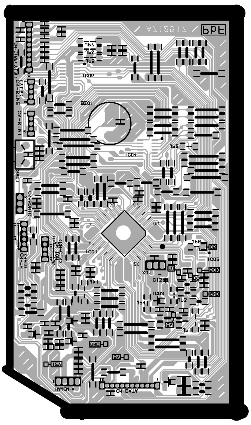
18 18

19 9.2. Outdoor Unit CS-E9EKEB CU-E9EKEB / CS-E12EKEB CU-E12EKEB 19
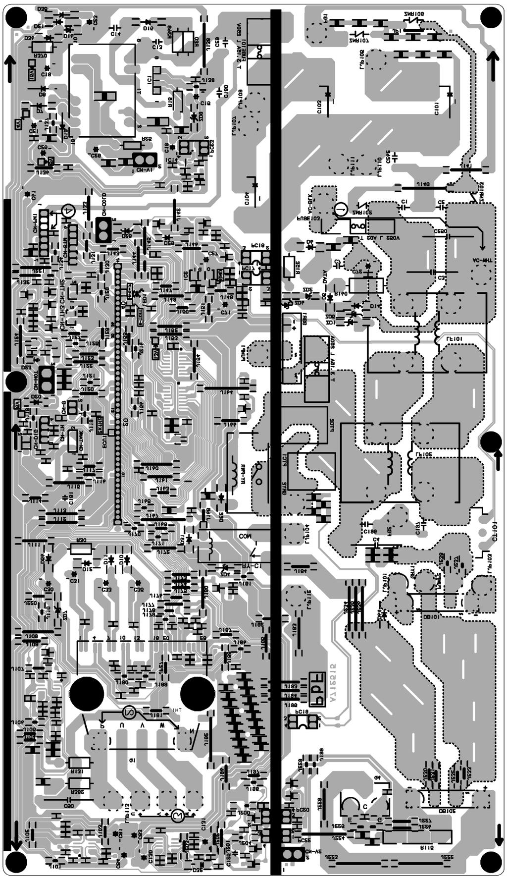
20 20
21 10 Simplified Electronic Circuit Diagram Indoor Unit CS-E9EKEB CU-E9EKEB / CS-E12EKEB CU-E12EKEB 21
22 10.2. Outdoor Unit 22
23 11 Installation Instructions Select The Best Location INDOOR UNIT There should not be any heat source or steam near the unit. There should not be any obstacles blocking the air circulation. A place where air circulation in the room is good. A place where drainage can be easily done. A place where noise prevention is taken into consideration. Do not install the unit near the door way. Ensure the spaces indicated by arrows from the wall, ceiling, fence or other obstacles. Recommended installation height for indoor unit shall be at least 2.5 m. Indoor/Outdoor Unit Installation Diagram CS-E9EKEB CU-E9EKEB / CS-E12EKEB CU-E12EKEB OUTDOOR UNIT If an awning is built over the unit to prevent direct sunlight or rain, be careful that heat radiation from the condenser is not obstructed. There should not be any animal or plant which could be affected by hot air discharged. Keep the spaces indicated by arrows from wall, ceiling, fence or other obstacles. Do not place any obstacles which may cause a short circuit of the discharged air. If piping length is over the rated length, additional refrigerant should be added as shown in the table. Model Piping size Rated Gas Liquid Length (m) Max. Elevation (m) Max. Piping Length (m) Additional Refrigerant (g/m) E9EK 3/8 1/ E12EK 1/2 1/ This illustration is for explanation purposes only. The indoor unit will actually face a different way. 23
24 11.2. Indoor Unit HOW TO FIX INSTALLATION PLATE The mounting wall is strong and solid enough to prevent it from the vibration TO DRILL A HOLE IN THE WALL AND INSTALL A SLEEVE OF PIPING 1. Insert the piping sleeve to the hole. 2. Fix the bushing to the sleeve. 3. Cut the sleeve until it extrudes about 15 mm from the wall. Caution When the wall is hollow, please be sure to use the sleeve for tube ass y to prevent dangers caused by mice biting the connecting cable. 4. Finish by sealing the sleeve with putty or caulking compound at the final stage. The centre of installation plate should be at more than 450 mm at right and left of the wall. The distance from installation plate edge to ceiling should more than 67 mm. From installation plate left edge to unit s left side is 74 mm. From installation plate right edge to unit s right is 94 mm. : For left side piping, piping connection for liquid should be about 15 mm from this line. : For left side piping, piping connection for gas should be about 45 mm from this line. : For left side piping, piping connection cable should be about 800 mm from this line. 1. Mount the installation plate on the wall with 5 screws or more. (If mounting the unit on the concrete wall consider using anchor bolts.) Always mount the installation plate horizontally by aligning the marking-off line with the thread and using a level gauge INDOOR UNIT INSTALLATION 1. For the right rear piping 2. Drill the piping plate hole with ø70 mm hole-core drill. Line according to the left and right side of the installation plate. The meeting point of the extended line is the centre of the hole. Another method is by putting measuring tape at position as shown in the diagram above. The hole centre is obtained by measuring the distance namely 150 mm and 125 mm for left and right hole respectively. Drill the piping hole at either the right or the left and the hole should be slightly slanted to the outdoor side. 2. For the right and right bottom piping 24
25 3. For the embedded piping CS-E9EKEB CU-E9EKEB / CS-E12EKEB CU-E12EKEB (This can be used for left rear piping & left bottom piping also.) 25

26 CONNECT THE CABLE TO THE INDOOR UNIT 1. The inside and outside connecting cable can be connected without removing the front grille. 2. Connecting cable between indoor unit and outdoor unit shall be approved polychloroprene sheathed mm 2 flexible cord, type designation 245 IEC 57 or heavier cord. Ensure the color of wires of outdoor unit and the terminal Nos. are the same to the indoor s respectively. Earth lead wire shall be longer than the other lead wires as shown in the figure for the electrical safety in case of the slipping out of the cord from the anchorage. Secure the cable onto the control board with the holder (clamper) INSTALLATION OF SUPER ALLERU-BUSTER FILTER 1. Open the front panel. 2. Remove the air filter. 3. Remove Supersonic air purifying device. 4. Open the Supersonic air purifying device frame. 5. Insert the super alleru-buster filter and close the Supersonic air purifying device frame as show in illustration at right HOW TO TAKE OUT FRONT GRILLE Please follow the steps below to take out front grille if necessary such as when servicing. 1. Set the vertical airflow direction louvers to the horizontal position. 2. Slide down the 2 caps on the front grille as shown in the illustration below, and then remove the 2 mounting screws. 3. Pull the lower section of the front grille towards you to remove the front grille. When reinstalling the front grille, first set the vertical airflow direction louvers to the horizontal position and then carry out above steps 2-3 in the reverse order. 26
27 11.3. Outdoor Unit INSTALL THE OUTDOOR UNIT After selecting the best location, start installation according to Indoor/Outdoor Unit Installation Diagram. 1. Fix the unit on concrete or rigid frame firmly and horizontally by bolt nut (ø10 mm). 2. When installing at roof, please consider strong wind and earthquake. Please fasten the installation stand firmly with bolt or nails. CS-E9EKEB CU-E9EKEB / CS-E12EKEB CU-E12EKEB CONNECTING THE PIPING Connecting The Piping To Indoor Unit Please make flare after inserting flare nut (locate at joint portion of tube assembly) onto the copper pipe. (In case of using long piping) Connect the piping Align the center of piping and sufficiently tighten the flare nut with fingers. Further tighten the flare nut with torque wrench in specified torque as stated in the table. MODEL Piping size (Torque) Gas Liquid E9EK 3/8 (42 N.m) 1/4 (18 N.m) E12EK 1/2 (55 N.m) 1/4 (18 N.m) Connecting The Piping To Outdoor Unit Decide piping length and then cut by using pipe cutter. Remove burrs from cut edge. Make flare after inserting the flare nut (located at valve) onto the copper pipe. Align center of piping to valves and then tighten with torque wrench to the specified torque as stated in the table. CUTTING AND FLARING THE PIPING 1. Please cut using pipe cutter and then remove the burrs. 2. Remove the burrs by using reamer. If burrs is not removed, gas leakage may be caused. Turn the piping end down to avoid the metal powder entering the pipe. 3. Please make flare after inserting the flare nut onto the copper pipes. 27
28 EVACUATION OF THE EQUIPMENT WHEN INSTALLING AN AIR CONDITIONER, BE SURE TO EVACUATE THE AIR INSIDE THE INDOOR UNIT AND PIPES in the following procedure. 1. Connect a charging hose with a push pin to the Low side of a charging set and the service port of the 3-way valve. Be sure to connect the end of the charging hose with the push pin to the service port. 2. Connect the center hose of the charging set to a vacuum pump with check valve, or vacuum pump and vacuum pump adaptor. 3. Turn on the power switch of the vacuum pump and make sure that the needle in the gauge moves from 0 cmhg (0 MPa) to -76 cmhg (-0.1 MPa). Then evacuate the air approximately ten minutes. 4. Close the Low side valve of the charging set and turn off the vacuum pump. Make sure that the needle in the gauge does not move after approximately five minutes. Note: BE SURE TO FOLLOW THIS PROCEDURE IN ORDER TO AVOID REFRIGERANT GAS LEAKAGE. 5. Disconnect the charging hose from the vacuum pump and from the service port of the 3-way valve. 6. Tighten the service port caps of the 3-way valve at a torque of 18 N.m with a torque wrench. 7. Remove the valve caps of both of the 2-way valve and 3-way valve. Position both of the valves to OPEN using a hexagonal wrench (4 mm). 8. Mount valve caps onto the 2-way valve and the 3-way valve. Be sure to check for gas leakage. CAUTION If gauge needle does not move from 0 cmhg (0 MPa) to -76 cmhg (-0.1 MPa), in step above take the following measure: If the leak stops when the piping connections are tightened further, continue working from step. If the leak does not stop when the connections are retightened, repair the location of leak. Do not release refrigerant during piping work for installation and reinstallation. Take care of the liquid refrigerant, it may cause frostbite CONNECT THE CABLE TO THE OUTDOOR UNIT (FOR DETAIL REFER TO WIRING DIAGRAM AT UNIT) 1. Remove the control board cover from the unit by loosening the screw. 2. Connecting cable between indoor unit and outdoor unit shall be approved polychloroprene sheathed mm 2 flexible cord, type designation 245 IEC 57 or heavier cord. 3. Secure the cable onto the control board with the holder (clamper). 4. Attach the control board cover back to the original position with the screw. 28

29 PIPE INSULATION CS-E9EKEB CU-E9EKEB / CS-E12EKEB CU-E12EKEB 1. Please carry out insulation at pipe connection portion as mentioned in Indoor/Outdoor Unit Installation Diagram. Please wrap the insulated piping end to prevent water from going inside the piping. 2. If drain hose or connecting piping is in the room (where dew may form), please increase the insulation by using POLY-E FOAM with thickness 6 mm or above OUTDOOR UNIT DRAIN WATER Water will drip from the basepan hole area during defrost function. To avoid water dripping, do not stand or place objects at this area CHECK THE DRAINAGE Open front panel and remove air filters. (Drainage checking can be carried out without removing the front grille.) Pour a glass of water into the drain tray-styrofoam. Ensure that water flows out from drain hose of the indoor unit EVALUATION OF THE PERFORMANCE Operate the unit at cooling operation mode for fifteen minutes or more. Measure the temperature of the intake and discharge air. Ensure the difference between the intake temperature and the discharge is more than 8 C. 29
30 12 Operation And Control Basic Function Inverter control, which equipped with a microcomputer in determining the most suitable operating mode as time passes, automatically adjusts output power for maximum comfort always. In order to achieve the suitable operating mode, the microcomputer maintains the set temperature by measuring the temperature of the environment and performing temperature shifting. The compressor at outdoor unit is operating following the frequency instructed by the microcomputer at indoor unit that judging the condition according to internal setting temperature and intake air temperature Internal Setting Temperature Once the operation starts, remote control setting temperature will be taken as base value for temperature shifting processes. These shifting processes are depending on the air conditioner settings and the operation environment. The final shifted value will be used as internal setting temperature and it is updated continuously whenever the electrical power is supplied to the unit Airflow Direction 1. There are two types of airflow, vertical airflow (directed by horizontal vane) and horizontal airflow (directed by vertical vanes). 2. Control of airflow direction can be automatic (angles of direction is determined by operation mode, heat exchanger temperature and intake air temperature) and manual (angles of direction can be adjusted using remote control) Vertical Airflow Operation Mode Airflow Direction Vane Angle ( ) Heating Auto with Heat Exchanger A Upward fix 3 Temperature B Downward fix 64 C Upward fix 3 D Downward fix 3 Manual Cooling, Soft Dry and Ion Auto 8 ~ 36 Manual Mode Judgment in Auto Auto 8 Manual Automatic vertical airflow direction can be set using remote control; the vane swings up and down within the angles as stated above. For heating mode operation, the angle of the vane depends on the indoor heat exchanger temperature as Figure 1 below. When the air conditioner is stopped using remote control, the vane will shift to close position. 2. Manual vertical airflow direction can be set using remote control; the angles of the vane are as stated above and the positions of the vane are as Figure 2 below. When the air conditioner is stopped using remote control, the vane will shift to close position. 30
31 Horizontal Airflow 1. Automatic horizontal airflow direction can be set using remote control; the vane swings left and right within the angles as stated below. For heating mode operation, the angle of the vane depends on the indoor heat exchanger temperature as Figure 1 below. Operation Mode Vane Angle ( ) Heating, with heat exchanger temperature A 65 ~ 115 B 90 Cooling, Soft Dry and Ion 65 ~ Manual horizontal airflow direction can be set using remote control; the angles of the vane are as stated below and the positions of the vane are as Figure 2 above. Pattern Airflow Direction Patterns at Remote Control Vane Angle ( ) Quiet operation (Cooling Mode/Cooling area of Dry Mode) A. Purpose To provide quiet cooling operation compare to normal operation. B. Control condition a. Quiet operation start condition When quiet button at remote control is pressed. Quiet LED illuminates. b. Quiet operation stop condition 1. When one of the following conditions is satisfied, quiet operation stops: a. Powerful button is pressed. b. Stop by OFF/ON switch. c. Timer off activates. d. Quiet button is pressed again. 31
32 2. When quiet operation is stopped, operation is shifted to normal operation with previous setting. 3. When fan speed is changed, quiet operation is shifted to quiet operation of the new fan speed. 4. When operation mode is changed, quiet operation is shifted to quiet operation of the new mode. 5. During quiet operation, if timer on activates, quiet operation maintains. 6. After off, when on back, quiet operation is not memorised. C. Control contents 1. Fan speed is changed from normal setting to quiet setting of respective fan speed. This is to reduce sound of Hi, Me, Lo for 3dB. 2. Fan speed for quiet operation is -1 step from setting fan speed Quiet operation (Heating) A. Purpose To provide quiet heating operation compare to normal operation. B. Control condition a. Quiet operation start condition When quiet button at remote control is pressed. Quiet LED illuminates. b. Quiet operation stop condition 1. When one of the following conditions is satisfied, quiet operation stops: a. Powerful button is pressed. b. Stop by OFF/ON switch. c. Timer off activates. d. Quiet button is pressed again. 2. When quiet operation is stopped, operation is shifted to normal operation with previous setting. 3. When fan speed is changed, quiet operation is shifted to quiet operation of the new fan speed. 4. When operation mode is changed, quiet operation is shifted to quiet operation of the new mode, except fan only mode. 5. During quiet operation, if timer on activates, quiet operation maintains. 6. After off, when on back, quiet operation is not memorised. C. Control contents a. Fan Speed manual 1. Fan speed is changed from normal setting to quiet setting of respective fan speed. This is to reduce sound of Hi, Me, Lo for 3dB. 2. Fan speed for quiet operation is -1 step from setting fan speed. 3. Fan Speed Auto Indoor FM RPM depends on pipe temp sensor of indoor heat exchanger. 32
33 Powerful Mode Operation When the powerful mode is selected, the internal setting temperature will shift to achieve the setting temperature quickly. (a) Cooling Operation (b) Soft Dry Operation (c) Heating Operation ON Timer Control ON timer can be set using remote control, the unit with timer set will start operate earlier than the setting time. This is to provide a comfortable environment when reaching the set ON time. 60 minutes before the set time, indoor (at fan speed of Lo-) and outdoor fan motor start operate for 30 seconds to determine the indoor intake air temperature and outdoor air temperature in order to judge the operation starting time. From the above judgment, the decided operation will start operate earlier than the set time as shown below OFF Timer Control OFF timer can be set using remote control, the unit with timer set will stop operate at set time. 33
34 Auto Restart Control 1. When the power supply is cut off during the operation of air conditioner, the compressor will re-operate within three to four minutes (there are 10 patterns between 2 minutes 58 seconds and 3 minutes 52 seconds to be selected randomly) after power supply resumes. 2. This type of control is not applicable during ON/OFF Timer setting Ionizer Operation Purpose To provide fresh air effect to users by discharging minus ion to air. Control Condition a. Ionizer Only Operation. 1. When air-conditioner unit is at OFF condition (standby) and ION operation button at remote control is pressed. Fan & ionizer on, ION LED illuminates, but power LED maintain off. (1 2) However, fan speed can be adjusted later by customer during this operation. Airflow direction (Horizontal Vane) control: Follow vane direction control at cooling mode. Horizontal vane can be changed by customer during ion only operation. b. Operation Mode + Ionizer Operation. 1. Ionising Operation Start Condition When air conditioner unit is in ON condition (Heat, Cool, Dry, Auto mode) and ION operation button at remote control is pressed. Ionizer on & ION LED illuminates. (3 4) Power LED also illuminates. 2. Ionising Operation Stop Condition When one of the following condition is satisfied, ION operation stops. a. Stopped by ON/OFF switch. b. Timer OFF activates. c. ION feedback signal shows error. 3. Ionizer operation status is not memorised by micon. After OFF, when operation is ON again, air conditioner operates without ionizer operation. 34
35 12.2. Protection Control Time Delay Safety Control Compressor will not start for three minutes after stop of the operation Seconds Forced Operation Once compressor starts the operation, it will not stop its operation for 30 seconds. However, it can be stopped with the remote controller or the Auto button on the indoor unit Total Running Current Control CS-E9EKEB CU-E9EKEB / CS-E12EKEB CU-E12EKEB 1. When the total running current exceeds l1, compressor operation frequency is reduced. If it reaches below l1, the operation frequency is increased. (But, up to programmed frequency.) 2. If total running current exceeds l2, compressor is stopped immediately. 3. If it happens three (3) times within 20 minutes, operation will be stopped and Timer LED blinks. ( F98 is activating.) Running current CS-E9EKEB CS-E12EKEB Cooling l1 3.7A 5.8A l2 25.0A 25.0A Heating l1 5.9A 8.2A l2 25.0A 25.0A IPM (Power transistor) Protection Control (DC Peak detection) Abnormal Current Control If inverter load current (DC peak) exceeds a rated value, compressor will be stopped immediately. When the excess occurs within 30 seconds after operation, it restarts in 1 minute and when after 30 seconds, restarts in 2 minutes. If the excess continuously occurs 7 times within 30 minutes after compressor starts, the unit will be stopped and timer LED on the indoor unit will be blinking. ( F99 is to be confirmed.) IPM Overheating Prevention Control If temperature of IPM exceeds 103 C, compressor will be stopped. It will restart in 2 minutes. Temperature for restarting: 90 C. If the excess occurs 4 times within 30 minutes after compressor starts, the compressor will be stopped and timer LED on the indoor unit will be blinking. ( F96 is to be confirmed.) Compressor Overheating Prevention Control 1. If discharge pipe temperature exceeds 100 C, compressor power will be limited. 2. If discharge pipe temperature exceeds 112 C, compressor will be stopped. 3. If the above excess occurs 4 times per 10 minutes, timer LED will be blinking. ( F97 is to be confirmed.) Outdoor High Pressure Prevention Control (Cooling and Dry operations) 1. If outdoor heat exchanger temperature exceeds 63 C in cooling or dry operation, compressor will be stopped. 2. Timer LED is not blinking. ( F95 is memorized, then.) Compressor Protection Control (Refrigeration Cycle Abnormality) In cooling and Dry operations 1. When compressor is operated continuously for 5 minutes in the maximum cooling power: a running current of A and [Indoor intake air temperature] - [Indoor heat exchanger temperature] < 4 C, compressor will be stopped. 2. If the above excess occurs twice for 20 minutes, timer LED is to be blinking. ( F91 is to be confirmed.) In Heating operation 1. When compressor is operated continuously for 5 minutes in the rated heating power: a running current of A and [Indoor heat exchanger temperature] - [Indoor intake air temperature] < 5 C, compressor will be stopped. 2. If the above excess occurs twice for 20 minutes, timer LED is to be blinking. ( F91 is to be confirmed.) 35
36 Four-way Valve Operation Detection Control (Switching Abnormality between Cooling and Heating) In Cooling operation 1. When indoor heat exchanger temperature exceeds 45 C in 4 minutes after compressor starts, compressor will be stopped. 2. If the above excess occurs 4 times per 30 minutes, timer LED is to be blinking. ( F11 is to be confirmed.) In Heating operation 1. When indoor heat exchanger temperature is below 0 C in 4 minutes after compressor starts, compressor will be stopped. 2. If the above excess occurs 4 times per 30 minutes, timer LED is to be blinking. ( F11 is to be confirmed.) Anti-Freezing Control (Cooling and Dry operations) Limit of Cooling power 1. When temperature of indoor heat exchanger is below 5 C, operating frequency will be decreased. 2. When temperature of indoor heat exchanger exceeds 7 C, operating frequency will be increased. (But, up to programmed frequency.) 3. When temperature of indoor heat exchanger is below 0 C continuously for 6 minutes, compressor will be stopped. 4. Timer LED is not blinking. ( F99 is memorized, then.) Limit of Indoor fan speed When temperature of indoor heat exchanger is below 6 C (2 C at Dry) continuously for 6 minutes, indoor fan speed will be increased by 50 rpm Outdoor Air Temperature Control In Cooling and Dry operations 1. When outdoor air temperature is below 25 C, the maximum power will be limited up to about % of the rated power. 2. When outdoor air temperature is below 18 C, the maximum power will be limited up to about % of the rated power. 3. When outdoor air temperature is below 11 C, the maximum power will be limited up to about 26-81% of the rated power Indoor Intake Air Temperature Control (Heating operation) 1. When indoor air temperature is 35 C or more, the maximum power will be limited up to the rated power. 2. When fan speed is set at Lo and intake air temperature is below 21 C, the maximum power will be limited up to the rated power. 36
37 13 Servicing Mode Auto Switch Operation CS-E9EKEB CU-E9EKEB / CS-E12EKEB CU-E12EKEB The below operations will be performed by pressing the AUTO switch. 1. AUTO OPERATION MODE The Auto operation will be activated immediately once the Auto Switch is pressed. 2. TEST RUN OPERATION (FOR PUMP DOWN/SERVICING PURPOSE) The Test Run operation will be activated if the Auto Switch is pressed continuously for more than 5 sec. A beep sound will occur at the fifth sec., in order to identify the starting of Test Run operation. 3. REMOTE CONTROLLER RECEIVING SOUND ON/OFF The ON/OFF of remote controller receiving sound can be change over by pressing the following step: a. Release the Auto Switch after Test Run operation is activated. b. Then, within 20 sec., after a., press Auto Switch for more than 5 sec. A beep beep sound will occur at the fifth sec., then release the Auto Switch. c. Within 20 sec. after b., press Auto Switch again. Everytime Auto Switch is pressed (within 20 sec. interval), remote controller receiving sound status will be reversed between ON and OFF. Long beep sound indicates that remote controller receiving sound is OFF. Short beep sound indicates that remote controller receiving sound is ON Indicator Panel LED POWER TIMER QUIET POWERFUL ION ALLERGEN BUSTER Color Green Orange Orange Orange Green Blue Light ON Operation ON Timer Setting ON Quiet Mode ON Powerful Mode ON Ion Mode ON Operation ON Light OFF Operation OFF Timer Setting OFF Quiet Mode OFF Powerful Mode OFF Ion Mode OFF Operation OFF Note: If POWER LED is blinking, the possible operations of the unit are Hot Start, during Deice operation, operation mode judgment, or ON timer sampling. If Timer LED is blinking, there is an abnormality operation occurs. If Ionizer, LED is blinking, there is an abnormality of Ionizer occurs. 37
38 14 Troubleshooting Guide Refrigeration Cycle System In order to diagnose malfunctions, make sure that there are no electrical problems before inspecting the refrigeration cycle. Such problems include insufficient insulation, problem with the power source, malfunction of a compressor and a fan. The normal outlet air temperature and pressure of the refrigeration cycle depends on various conditions, the standard values for them are shown in the table to the right. 38
39 14.2. Relationship Between The Condition Of The Air Conditioner And Pressure And Electric Current Cooling Mode Condition of the air conditoner Low Pressure High Pressure Electric current during operation Heating Mode Low Pressure High Pressure Electric current during operation Insufficient refrigerant (gas leakage) Clogged capillary tube or Strainer Short circuit in the indoor unit Heat radiation deficiency of the outdoor unit Inefficient compression Carry on the measurements of pressure, electric current, and temperature fifteen minutes after an operation is started Breakdown Self Diagnosis Function Once abnormality detected during operation, the unit will immediately stop its operation (Timer LED is blinking) and maximum of three error codes (abnormality) will be saved in memory. The abnormality of the operation can be identified through the below breakdown diagnosis method: Press CHECK button at remote controller continuously for more than five seconds to turn on the diagnosis mode, H11 will be displayed at remote controller. By pressing the TMER button once, next error code will be displayed; press V button once, previous error code will be displayed. If error code displayed matches the error code saved in unit memory (abnormality detected), beep, beep, beep... sounds will be heard for 4 seconds and Power LED will light on. Otherwise, one beep sound is heard. If CHECK button is press again or without any operation for 30 seconds, the diagnosis mode will turn off. 39
40 14.4. Error Codes Table Diagnosis display Abnormality / Protection control Abnormality Judgement Emergency operation Primary location to verify H00 No abnormality detected Normal operation H11 Indoor / outdoor abnormal communication > 1 min after starting operation Indoor fan operation only Internal / external cable connections Indoor / Outdoor PCB H12 Connection capability rank abnormal H14 Indoor intake air temperature sensor abnormality Continue for 5 sec. Intake air temperature sensor (detective or disconnected) H15 Outdoor compressor temperature sensor abnormality Continue for 5 sec. Compressor temperature sensor (detective or disconnected) H16 Outdoor Current Transformer open circuit Outdoor PCB IPM (Power transistor) module H19 Indoor fan motor merchanism locked Indoor PCB Fan motor H23 Indoor heat exchanger temperature sensor abnormality Continue for 5 sec. O (Cooling only) Heat exchanger temperature sensor (defective or disconnected) H26 Ionizer breakdown Ionizer H27 Outdoor intake air temperature sensor abnormality Continue for 5 sec. O Outdoor temperature sensor (defective or disconnected) H28 Outdoor heat exchanger temperature sensor abnormality Continue for 5 sec. O Outdoor heat exchanger temperature sensor (defective or disconnected) Continue for 5 sec. Outdoor temperature sensor (defective or disconnected) H30 Outdoor discharge air temperature sensor abnormality H33 Indoor/Outdoor wrong connection Indoor/Outdoor supply voltage H38 Indoor / outdoor mismatch (brand code) H97 Outdoor fan motor mechanism locked 2 times occurance Indoor PCB within 30 minutes Fan motor H98 Indoor high pressure protection Air filter dirty Air circulation short circuit H99 Indoor heat exchanger anti-freezing protection Insufficient refrigerant Air filter dirty F11 Cooling / Heating cycle changeover abnormality 4 times occurance within 30 minutes 4-way valve V-coil F90 PFC control 4 times occurance Voltage at PFC within 10 minutes F91 Refrigeration cycle abnormality 2 times occurance within 20 minutes No refrigerant (3-way valve is closed) F93 Compressor rotation failure Compressor F95 Cool high pressure protection 4 times occurance Outdoor refrigerant circuit within 20 minutes F96 IPM (power transistor) overheating protection Excess refrigerant Improper heat radiation IPM (Power transistor) F97 Outdoor compressor overheating protection 4 times occurance within 10 minutes Insufficient refrigerant Compressor F98 Total running current protection 3 times occurance within 20 minutes Excess refrigerant Improper heat radiation F99 Outdoor Direct Current (DC) peak detection 7 times occurance continuously Outdoor PCB IPM (Power transistor) Compressor Note: O - Frequency measured and fan speed fixed. The memory data of error code is erased when the power supply is cut off, or press the Auto Switch until beep sound heard following by pressing the RESET button at remote controller. Although operation forced to stop when abnormality detected, emergency operation is possible for certain errors (refer to Error Codes Table) by using remote controller or Auto Switch at indoor unit. However, the remote controller signal receiving sound is changed from one beep to four beep sounds. 40


41 CS-E9EKEB CU-E9EKEB / CS-E12EKEB CU-E12EKEB 15 Disassembly and Assembly Instructions Caution! When handling electronic controller, be careful of electrostatic discharge. Be sure to return the wiring to its original position. There are many high voltage components within the heat sink cover so never touch the interior during operation. Wait at least two minutes after power has been turned off Indoor Electronic Controller and Control Board 41

42 CS-E9EKEB CU-E9EKEB / CS-E12EKEB CU-E12EKEB 42


43 15.2. Indoor Cross Flow Fan and Fan Motor 43

44 44


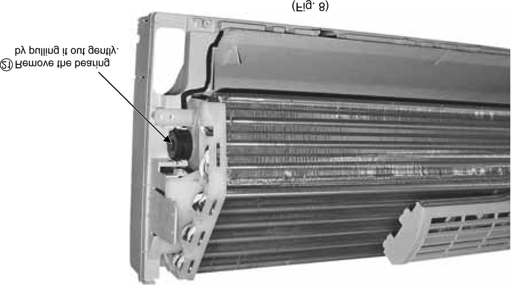
45 15.3. Outdoor Propeller Fan and Fan Motor CS-E9EKEB CU-E9EKEB / CS-E12EKEB CU-E12EKEB 45
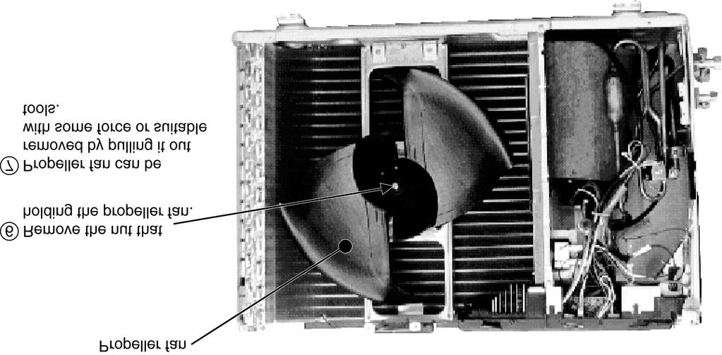

46 46
47 16 Technical Data CS-E9EKEB CU-E9EKEB CS-E9EKEB CU-E9EKEB / CS-E12EKEB CU-E12EKEB Cooling Characteristic at Different Outdoor Air Temperature Condition Indoor room temperature: 27/19 C Remote control setting: HI fan, COOL 16 C Compressor frequency: rated cooling Voltage: 230 V 47
48 Heating Characteristic at Different Outdoor Air Temperature Condition Indoor room temperature: 20 C Remote control setting: HI fan, HEAT 30 C Compressor frequency: rated heating Voltage: 230 V 48
49 49
50 Cooling Characteristic at Different Piping Length Condition Indoor room temperature: 27/19 C Remote control setting: HI fan, COOL 16 C Compressor frequency: rated cooling Voltage: 230 V 50
51 Heating Characteristic at Different Piping Length Condition Indoor room temperature: 20 C Remote control setting: HI fan, HEAT 30 C Compressor frequency: rated heating Voltage: 230 V 51
52 52
53 16.2. CS-E12EKEB CU-E12EKEB CS-E9EKEB CU-E9EKEB / CS-E12EKEB CU-E12EKEB Cooling Characteristic at Different Outdoor Air Temperature Condition Indoor room temperature: 27/19 C Remote control setting: HI fan, COOL 16 C Compressor frequency: rated cooling Voltage: 230 V 53
54 Heating Characteristic at Different Outdoor Air Temperature Condition Indoor room temperature: 20 C Remote control setting: HI fan, HEAT 30 C Compressor frequency: rated heating Voltage: 230 V 54
55 55
56 Cooling Characteristic at Different Piping Length Condition Indoor room temperature: 27/19 C Remote control setting: HI fan, COOL 16 C Compressor frequency: rated cooling Voltage: 230 V 56
57 Heating Characteristic at Different Piping Length Condition Indoor room temperature: 20 C Remote control setting: HI fan, HEAT 30 C Compressor frequency: rated heating Voltage: 230 V 57
58 16.3. Sensible Capacity Chart Condition Indoor temperature : 27 C / 19 C Outdoor temperature : 35 C / 24 C CS-E9EKEB CU-E9EKEB 230V Outdoor Temperature ( C) Indoor wet bulb temperature TC SHC IP TC SHC IP TC SHC IP TC SHC IP 17.0 C C C C CS-E12EKEB CU-E12EKEB 230V Outdoor Temperature ( C) Indoor wet bulb temperature TC SHC IP TC SHC IP TC SHC IP TC SHC IP 17.0 C C C C TC - Total Cooling Capacity (kw) SHC - Sensible Heat Capacity (kw) IP - Input Power (kw) 58
59 17 Exploded View And Replacement Parts List CS-E9EKEB CS-E12EKEB CS-E9EKEB CU-E9EKEB / CS-E12EKEB CU-E12EKEB Note: The above exploded view is for the purpose of parts disassembly and replacement. The non-numbered parts are not kept as standard service parts. 59
60 17.2. CS-E9EKEB CS-E12EKEB REF. NO. PART NAME & DESCRIPTION QTY. CS-E9EKEB CS-E12EKEB Remarks 1 CHASSY COMPLETE 1 CWD50C FAN MOTOR, DC 30W 3PH 1 CWA981149J O 3 CROSS FLOW FAN COMPLETE 1 CWH02C BEARING ASSY 1 CWH64K007 5 SCREW - CROSS FLOW FAN 1 CWH EVAPORATOR CO. 1 CWB30C1832 CWB30C FLARE NUT (1/4) 1 CWT FLARE NUT (3/8) (1/2) 1 CWT CWT CLIP FOR SENSOR 1 CWH DISCHARGE GRILLE COMPLETE 1 CWE20C VERTICAL VANE 9 CWE CONNECTING BAR 1 CWE CONNECTING BAR 1 CWE A.S.MOTOR, DC SINGLE 12V 300Ω 2 CWA98260+MJ O 15 LEADWIRE - AIR SWING MOTOR 1 CWA67C CAP - DRAIN TRAY 1 CWH HORIZONTAL VANE 1 CWE BACK COVER CHASSIS 1 CWD CONTROL BOARD CASING 1 CWH TERMINAL BOARD COMPLETE 1 CWA28C2069 O 21 P.S CORD WITHOUT PLUG 1 CWA20C ELECTRONIC CONTROLLER - MAIN 1 CWA73C2014 CWA73C2015 O 23 LEAD WIRE - AIR SWING MOTOR 1 CWA67C3977 O 24 ELECTRONIC CONTROLLER - POWER 1 CWA SENSOR COMPLETE 1 CWA50C2321 O 26 CONTROL BOARD FRONT COVER CO. 1 CWH13C INDICATOR COMPLETE 1 CWE39C1126 O 28 INDICATOR HOLDER 1 CWD INDICATOR HOLDER 1 CWD CONTROL BOARD TOP COVER 1 CWH REMOTE CONTROL COMPLETE 1 CWA75C2807 O 32 FRONT GRILLE CO. 1 CWE11C3138 O 33 INTAKE GRILLE COMPLETE 1 CWE22C GRILLE DOOR 1 CWE AIR FILTER 2 CWD SCREW - FRONT GRILLE 2 XTT4+16CFJ 37 CAP - FRONT GRILLE 2 CWH DRAIN HOSE 1 CWH INSTALLATION PLATE 1 CWH BAG COMP. - INSTALLATION SCREW 1 CWH82C FULCRUM 1 CWH ELECTRONIC CONTROLLER - IONIZER 1 CWA O 43 CASING - IONIZER 1 CWD CASING - IONIZER 1 CWD ION GENERATOR 1 CWH94C SUPERSONIC AIR PURIFYING DEVICE 1 CWH91C ELEC. CONTROLLER - SUPERSONIC 1 CWA O 48 SUPER ALLERU BUSTER FILTER 1 CWD00C FRAME FR AIR FILTER SUPERSONIC 1 CWD FRAME FR AIR FILTER SUPERSONIC 1 CWD (Note) All parts are supplied from PHAAM, Malaysia (Vendor Code: 061). O marked parts are recommended to be kept in stock. 60
National Building Code of Finland, Part D1, Building Water Supply and Sewerage Systems, Regulations and guidelines 2007
 National Building Code of Finland, Part D1, Building Water Supply and Sewerage Systems, Regulations and guidelines 2007 Chapter 2.4 Jukka Räisä 1 WATER PIPES PLACEMENT 2.4.1 Regulation Water pipe and its
LYTH-CONS CONSISTENCY TRANSMITTER
 LYTH-CONS CONSISTENCY TRANSMITTER LYTH-INSTRUMENT OY has generate new consistency transmitter with blade-system to meet high technical requirements in Pulp&Paper industries. Insurmountable advantages are
Solar Water Heater Kit. EcoStyle. 1 User Manual/Operating Instructions. Contents FREE LESSON PLANS AVAILABLE.
 EcoStyle 1 User Manual/Operating Instructions Contents 1 Contents 2 What s in the box? 3 Setting up the 4 Heating water 5 Measuring water temperature with the digital thermometer 6 Maximum/minimum temperature
1. SIT. The handler and dog stop with the dog sitting at heel. When the dog is sitting, the handler cues the dog to heel forward.
 START START SIT 1. SIT. The handler and dog stop with the dog sitting at heel. When the dog is sitting, the handler cues the dog to heel forward. This is a static exercise. SIT STAND 2. SIT STAND. The
CONVERSION KITS FOR FRAMES MR8 AND MR9 INSTALLATION INSTRUCTIONS
 CONVERSION KITS FOR FRAMES MR8 AND MR9 INSTALLATION INSTRUCTIONS MR8 AND MR9 CONVERSION KIT - INSTALLATION INSTRUCTION Document ID: DPD01787, Revision: A, Release date: 17.11.2015 1.1 MR8 kit contents
1/4. Resetointi ja vianmääritys. 22.11.2013 ntr
 A400-64176 Sähköpöydät 1/4 Resetointi ja vianmääritys Pöydän resetointi tehdään aina ennen käyttöönottoa ja tarvittaessa häiriötilanteessa. Määritä pöydän tyyppi käyttökytkimen ja jalustan mukaan ja tee
Owner s Manual GREE Electric Appliances,Inc.of zhuhai
 Ilmalämpöpumppu Split air conditioner wall mounted model Käyttäjän opas Owner s Manual GREE Electric Appliances,Inc.of zhuhai Ultra-thin GWHD09A3NK3DF KFR-25GW/NaA12FA GWHD12B2NK3AD KFR-32GW/NaA12FA Please
SAGA 150. Asennusohjeet. Mittaa oven korkeus. Piirrä seinään oven kiinni -päätyyn seinäkannattimen kohdalle vaakaviiva korkeudelle ovi + 75mm + 20 mm.
 SAGA 150 Asennusohjeet 500 1 2 Mittaa oven korkeus. Piirrä seinään oven kiinni -päätyyn seinäkannattimen kohdalle vaakaviiva korkeudelle ovi + 75mm + 20 mm. 3 Piirrä vesivaa an avulla viiva myös kiskon
PAINEILMALETKUKELA-AUTOMAATTI AUTOMATIC AIR HOSE REEL
 MAV4 MAV5 MAV6 PAINEILMALETKUKELA-AUTOMAATTI AUTOMATIC AIR HOSE REEL Käyttöohje Instruction manual HUOMIO! Lue käyttöohjeet huolellisesti ennen laitteen käyttöä ja noudata kaikkia annettuja ohjeita. Säilytä
Secto Design Oy Kauppalantie 12 02700 Kauniainen Finland tel. +358 9 5050598 fax +358 9 5475 2535 info@sectodesign.fi www.sectodesign.
 Secto Design Oy Kauppalantie 12 02700 Kauniainen Finland tel. +358 9 5050598 fax +358 9 5475 2535 info@sectodesign.fi www.sectodesign.fi Secto 4200 pendant natural birch, black or white laminate, walnut
WINE COOLER TFW METOS TFW 160S, TFW 365-2S, TFW 375S MG ,
 WINE COOLER TFW METOS TFW 160S, TFW 365-2S, TFW 375S MG4116794, 4116798, 4116797 Instruction manual TWF 365-2S TWF 375S TWF 160S 01.09.2015 Table if Contents 1. Important safety instructions...3 2. Unpacking
TM ETRS-TM35FIN-ETRS89 WTG
 SHADOW - Main Result Assumptions for shadow calculations Maximum distance for influence Calculate only when more than 20 % of sun is covered by the blade Please look in WTG table WindPRO version 2.8.579
Recirkulering. El-tilslutning. Kontrolpanel. Dansk. Timerfunktion
 1 2 Dansk Recirkulering Luften renses ved hjælp at aktive kulfiltre hvorefter den returneres til rummet. Kulfiltre bestilles separat. El-tilslutning Emhætten skal tilsluttes 230 V i henhold til stærkstrømsreglementet.
Capacity Utilization
 Capacity Utilization Tim Schöneberg 28th November Agenda Introduction Fixed and variable input ressources Technical capacity utilization Price based capacity utilization measure Long run and short run
TM ETRS-TM35FIN-ETRS89 WTG
 SHADOW - Main Result Assumptions for shadow calculations Maximum distance for influence Calculate only when more than 20 % of sun is covered by the blade Please look in WTG table WindPRO version 2.9.269
INSTALLATION INSTRUCTION ASENNUSOHJE PEM1417 2012-11 ENGLISH SUOMI CURRENT LIMITING DEVICE VIRTAA RAJOITTAVA SUOJA SDI46.812 & SDI46.
 INSTALLATION INSTRUCTION ASENNUSOHJE PEM1417 2012-11 ENGLISH SUOMI CURRENT LIMITING DEVICE VIRTAA RAJOITTAVA SUOJA SDI46.812 & SDI46.824 2/8 SDI46.812 & SDI46.824 PEM1417 2012-11 ENGLISH GENERAL INFORMATION
( ( OX2 Perkkiö. Rakennuskanta. Varjostus. 9 x N131 x HH145
 OX2 9 x N131 x HH145 Rakennuskanta Asuinrakennus Lomarakennus Liike- tai julkinen rakennus Teollinen rakennus Kirkko tai kirkollinen rak. Muu rakennus Allas Varjostus 1 h/a 8 h/a 20 h/a 0 0,5 1 1,5 2 km
Yhtiön nimi: - Luotu: - Puhelin: - Fax: - Päiväys: -
 Positio Laske Kuvaus 1 MAGNA 32-1 N Tuote No.: 98117 Huom.! Tuotteen kuva voi poiketa todellisesta tuotteesta The pump is of the canned rotor type, i.e. pump and motor form an integral unit without shaft
Tynnyrivaara, OX2 Tuulivoimahanke. ( Layout 9 x N131 x HH145. Rakennukset Asuinrakennus Lomarakennus 9 x N131 x HH145 Varjostus 1 h/a 8 h/a 20 h/a
 , Tuulivoimahanke Layout 9 x N131 x HH145 Rakennukset Asuinrakennus Lomarakennus 9 x N131 x HH145 Varjostus 1 h/a 8 h/a 20 h/a 0 0,5 1 1,5 km 2 SHADOW - Main Result Assumptions for shadow calculations
VAROITUKSET. Älä pura laitetta osiin.
 VAROITUKSET Laitteen väärinkäyttö voi johtaa henkilövahinkoihin. Noudata kaikkia tässä ohjekirjassa annettuja ohjeita ja käytä laitetta oikein. Älä koskaan seiso laitteen alapuolella. Älä pura laitetta
TM ETRS-TM35FIN-ETRS89 WTG
 SHADOW - Main Result Assumptions for shadow calculations Maximum distance for influence Calculate only when more than 20 % of sun is covered by the blade Please look in WTG table WindPRO version 2.8.579
Metsälamminkankaan tuulivoimapuiston osayleiskaava
 VAALAN KUNTA TUULISAIMAA OY Metsälamminkankaan tuulivoimapuiston osayleiskaava Liite 3. Varjostusmallinnus FCG SUUNNITTELU JA TEKNIIKKA OY 12.5.2015 P25370 SHADOW - Main Result Assumptions for shadow calculations
Secto 4200 pendant natural birch, black or white laminate, walnut veneer
 Secto Design Oy Kauppalantie 12 02700 Kauniainen Finland tel. +358 9 5050598 fax +358 9 5475 2535 info@sectodesign.fi www.sectodesign.fi Secto 4200 pendant natural birch, black or white laminate, walnut
TM ETRS-TM35FIN-ETRS89 WTG
 VE1 SHADOW - Main Result Calculation: 8 x Nordex N131 x HH145m Assumptions for shadow calculations Maximum distance for influence Calculate only when more than 20 % of sun is covered by the blade Please
TM ETRS-TM35FIN-ETRS89 WTG
 SHADOW - Main Result Assumptions for shadow calculations Maximum distance for influence Calculate only when more than 20 % of sun is covered by the blade Please look in WTG table WindPRO version 2.8.579
I-VALO VEGA FIXING MODULE B300
 Nämä ohjeet eivät välttämättä sisällä kaikkien valaisinten tai tarvikkeiden yksityiskohtaisia ohjeita, eivätkä ohjeista kaikissa asennukseen ja käyttöön tai huoltoon liittyvissä tilanteissa. / These instructions
Fitting instructions. Fitting set for joining all types of DEVI self limiting heating cables to heating cables Art. no. 19805779 SSTL nro 04 312 85
 GB/FI Fitting instructions Fitting set for joining all types of DEVI self limiting heating cables to heating cables Art. no. 19805779 SSTL nro 04 312 85 intelligent varme Contents: GB Connection kits 3
KONEISTUSKOKOONPANON TEKEMINEN NX10-YMPÄRISTÖSSÄ
 KONEISTUSKOKOONPANON TEKEMINEN NX10-YMPÄRISTÖSSÄ https://community.plm.automation.siemens.com/t5/tech-tips- Knowledge-Base-NX/How-to-simulate-any-G-code-file-in-NX- CAM/ta-p/3340 Koneistusympäristön määrittely
Asennusopas. DEVIreg 531. Elektroninen termostaatti.
 Asennusopas DEVIreg 531 Elektroninen termostaatti www.devi.com Sisällysluettelo 1 Johdanto................. 3 1.1 Tekniset tiedot.......... 4 1.2 Turvaohjeet............ 5 2 Asennusohjeet.............
WindPRO version joulu 2012 Printed/Page :42 / 1. SHADOW - Main Result
 SHADOW - Main Result Assumptions for shadow calculations Maximum distance for influence Calculate only when more than 20 % of sun is covered by the blade Please look in WTG table 13.6.2013 19:42 / 1 Minimum
TM ETRS-TM35FIN-ETRS89 WTG
 SHADOW - Main Result Assumptions for shadow calculations Maximum distance for influence Calculate only when more than 20 % of sun is covered by the blade Please look in WTG table 5.11.2013 16:44 / 1 Minimum
WindPRO version joulu 2012 Printed/Page :47 / 1. SHADOW - Main Result
 SHADOW - Main Result Assumptions for shadow calculations Maximum distance for influence Calculate only when more than 20 % of sun is covered by the blade Please look in WTG table WindPRO version 2.8.579
Information on preparing Presentation
 Information on preparing Presentation Seminar on big data management Lecturer: Spring 2017 20.1.2017 1 Agenda Hints and tips on giving a good presentation Watch two videos and discussion 22.1.2017 2 Goals
FinFamily PostgreSQL installation ( ) FinFamily PostgreSQL
 FinFamily PostgreSQL") FinFamily PostgreSQL 1 Sisällys / Contents FinFamily PostgreSQL... 1 1. Asenna PostgreSQL tietokanta / Install PostgreSQL database... 3 1.1. PostgreSQL tietokannasta / About the PostgreSQL database...
FinFamily PostgreSQL 1 Sisällys / Contents FinFamily PostgreSQL... 1 1. Asenna PostgreSQL tietokanta / Install PostgreSQL database... 3 1.1. PostgreSQL tietokannasta / About the PostgreSQL database...
,0 Yes ,0 120, ,8
 SHADOW - Main Result Calculation: Alue 2 ( x 9 x HH120) TuuliSaimaa kaavaluonnos Assumptions for shadow calculations Maximum distance for influence Calculate only when more than 20 % of sun is covered
TM ETRS-TM35FIN-ETRS89 WTG
 SHADOW - Main Result Assumptions for shadow calculations Maximum distance for influence Calculate only when more than 20 % of sun is covered by the blade Please look in WTG table WindPRO version 2.8.579
TM ETRS-TM35FIN-ETRS89 WTG
 SHADOW - Main Result Assumptions for shadow calculations Maximum distance for influence Calculate only when more than 20 % of sun is covered by the blade Please look in WTG table WindPRO version 2.8.579
TM ETRS-TM35FIN-ETRS89 WTG
 SHADOW - Main Result Assumptions for shadow calculations Maximum distance for influence Calculate only when more than 20 % of sun is covered by the blade Please look in WTG table 22.12.2014 11:33 / 1 Minimum
INSTALLATION INSTRUCTION ASENNUSOHJE PEM SJTK31 SJTK46 ENGLISH SUOMI
 INSTALLATION INSTRUCTION ASENNUSOHJE PEM1256 2010-2 SJTK31 SJTK46 ENGLISH SUOMI GB GENERAL INFORMATION - Check that the kit is suitable for the cable type. - Check the materials listed in the bill of materials
TM ETRS-TM35FIN-ETRS89 WTG
 SHADOW - Main Result Calculation: N117 x 9 x HH141 Assumptions for shadow calculations Maximum distance for influence Calculate only when more than 20 % of sun is covered by the blade Please look in WTG
Työmaadoitusvälineet suurjännitteelle
 Työmaadoitusvälineet suurjännitteelle Eurolaite Oy on vuonna 1 perustettu sähkötekniikan tuotteiden maahantuontiin, markkinointiin ja myyntiin erikoistunut asiantuntijayritys. Keskeisenä tavoitteena on
Kitchen Pendant 2/10/19
 Kitchen Pendant Kitchen Pendant Dining Area Dining Area Living Area Dining Area Bathroom 201 Quantity: 2 W A L L C O L L E C T I O N Voto Wall Square DESCRIPTION The Voto light by Tech Lighting is simply
( ,5 1 1,5 2 km
 Tuulivoimala Rakennukset Asuinrakennus Liikerak. tai Julkinen rak. Lomarakennus Teollinen rakennus Kirkollinen rakennus Varjostus "real case" h/a 1 h/a 8 h/a 20 h/a 4 5 3 1 2 6 7 8 9 10 0 0,5 1 1,5 2 km
On instrument costs in decentralized macroeconomic decision making (Helsingin Kauppakorkeakoulun julkaisuja ; D-31)
") On instrument costs in decentralized macroeconomic decision making (Helsingin Kauppakorkeakoulun julkaisuja ; D-31) Juha Kahkonen Click here if your download doesn"t start automatically On instrument costs
On instrument costs in decentralized macroeconomic decision making (Helsingin Kauppakorkeakoulun julkaisuja ; D-31) Juha Kahkonen Click here if your download doesn"t start automatically On instrument costs
Käyttäjän opas. Ilmalämpöpumppu. Linge wind GWHD09A3NK3DD GWHD12A6NK3DC KAHIL
 Ilmalämpöpumppu Käyttäjän opas Linge wind GWHD09A3NK3DD GWHD12A6NK3DC Lukekaa tämä Käyttäjän opas huolellisesti ennen laitteen asennusta ja käyttöä. KAHIL SISÄLLYS Ilmalämpöpumpun rakenne... 1 Ohjeita
Lämmitysjärjestelmät
 METSTA Rakennusten energiatehokkuusstandardit uudistuvat seminaari 26.4.2017 Lämmitysjärjestelmät Jarek Kurnitski HEAT GAINS BUILDING PROPERTIES CLIMATIC CONDITIONS INDOOR ENVIRONMENT REQUIREMENTS EN 16789-1
Särmäystyökalut kuvasto Press brake tools catalogue
 Finnish sheet metal machinery know-how since 1978 Särmäystyökalut kuvasto Press brake tools catalogue www.aliko.fi ALIKO bending chart Required capacity in kn (T) in relation to V-opening. V R A S = plates
Exercise 1. (session: )
") EEN-E3001, FUNDAMENTALS IN INDUSTRIAL ENERGY ENGINEERING Exercise 1 (session: 24.1.2017) Problem 3 will be graded. The deadline for the return is on 31.1. at 12:00 am (before the exercise session). You
EEN-E3001, FUNDAMENTALS IN INDUSTRIAL ENERGY ENGINEERING Exercise 1 (session: 24.1.2017) Problem 3 will be graded. The deadline for the return is on 31.1. at 12:00 am (before the exercise session). You
Returns to Scale II. S ysteemianalyysin. Laboratorio. Esitelmä 8 Timo Salminen. Teknillinen korkeakoulu
 Returns to Scale II Contents Most Productive Scale Size Further Considerations Relaxation of the Convexity Condition Useful Reminder Theorem 5.5 A DMU found to be efficient with a CCR model will also be
TM ETRS-TM35FIN-ETRS89 WTG
 SHADOW - Main Result Assumptions for shadow calculations Maximum distance for influence Calculate only when more than 20 % of sun is covered by the blade Please look in WTG table WindPRO version 2.8.579
Victo Finishes Shade Cable + ceiling cup Natural birch White White laminated White Black laminated Black Walnut veneer White.
 Victo 4250 Finishes Shade Cable + ceiling cup Natural birch White White laminated White Black laminated Black Walnut veneer White Material Sizes Light source Cable IP Rating Maintenance Form pressed birch
R32 CAUTION AIR CONDITIONER
 Do not use means to accelerate the defrosting process or to clean, other than those recommended by the manufacturer. ny unfi t method or using incompatible material may cause product damage, burst and
performance DHW coil type exchanger Diverter valve Analogue thermostat control panel Heating pump DHW pump Digital electronic control panel
 ACTIVA HIGH PERFORMANCE STEEL HEATER UNIT HIGH PERFORMANCE STEEL HEATER UNIT ACTIVA PLUS High energy efficiency obtained due to the LASIAN body structural features of high heat exchange surface area and
Installation instruction PEM
 Installation instruction ASENNUSOHJE PEM1032 2010-02 SURGE ARRESTER SET FOR POLE MOUNT TRANSFORMER YLIJÄNNITESUOJASETTI PYLVÄSMUUNTAJALLE ENGLISH SUOMI 2/8 PEM1032 2010-02 ENGLISH GENERAL INFORMATION -
Secto Design Oy Kauppalantie Kauniainen Finland tel fax
 Secto Design Oy Kauppalantie 12 02700 Kauniainen Finland tel. +358 9 5050598 fax +358 9 5475 2535 info@sectodesign.fi www.sectodesign.fi Secto 4202 Magnum pendant Available in natural birch, black or white
Octo Finishes Shade Cable + ceiling cup Natural birch White White laminated White Black laminated Black Walnut veneer White.
 Octo 4240 Finishes Shade Cable + ceiling cup Natural birch White White laminated White Black laminated Black Walnut veneer White Material Sizes Light source Cable IP Rating Maintenance Form pressed birch
Keskittämisrenkaat. Meiltä löytyy ratkaisu jokaiseen putkikokoon, 25 mm ja siitä ylöspäin.
 Keskittämisrenkaat Keskittämisrenkaita käytetään kun virtausputki menee suojaputken sisällä, kuten esim. tiealituksissa. Meidän keskittämisrenkaat ovat valmistettu polyeteenistä jonka edut ovat: - helppo
Exercise 3. (session: )
") 1 EEN-E3001, FUNDAMENTALS IN INDUSTRIAL ENERGY ENGINEERING Exercise 3 (session: 7.2.2017) Problem 3 will be graded. The deadline for the return is on 28.2. at 12:00 am (before the exercise session). You
1 EEN-E3001, FUNDAMENTALS IN INDUSTRIAL ENERGY ENGINEERING Exercise 3 (session: 7.2.2017) Problem 3 will be graded. The deadline for the return is on 28.2. at 12:00 am (before the exercise session). You
Gap-filling methods for CH 4 data
 Gap-filling methods for CH 4 data Sigrid Dengel University of Helsinki Outline - Ecosystems known for CH 4 emissions; - Why is gap-filling of CH 4 data not as easy and straight forward as CO 2 ; - Gap-filling
BRUTTO PINTA- ALA (M 2 ) KEHYKSEN MATERIAAL I. EA-HP-1500/47-18 Super heat ALUMIINI 1,98 108 0,172 506 1320*1680*110 59
 KEHYKSEN MATERIAAL I. EA-HP-1500/47-18 Super heat ALUMIINI 1,98 108 0,172 506 1320*1680*110 59") TYHJIÖPUTKIKERÄIMET 1. EA-HP HEAT PIPE TYHJIÖPUTKIKERÄIMEN HINTA JA TEKNISET TIEDOT KUVA MALLI KERÄIN MENETELMÄ KEHYKSEN MATERIAAL I BRUTTO PINTA- ALA (M 2 ) MAX. LÄMMITETT ÄVÄ VESIMÄÄRÄ / KERÄIME N TILAVUU
TYHJIÖPUTKIKERÄIMET 1. EA-HP HEAT PIPE TYHJIÖPUTKIKERÄIMEN HINTA JA TEKNISET TIEDOT KUVA MALLI KERÄIN MENETELMÄ KEHYKSEN MATERIAAL I BRUTTO PINTA- ALA (M 2 ) MAX. LÄMMITETT ÄVÄ VESIMÄÄRÄ / KERÄIME N TILAVUU
Installation instruction PEM
 Installation instruction ASENNUSOHJE PEM1031 2010-04 CURRENT LIMITING DEVICE FOR POLE MOUNT TRANSFORMER VIRTAA RAJOITTAVA SUOJA PYLVÄSMUUNTAJALLE ENGLISH SUOMI 75 2/8 PEM1031 2010-04 ENGLISH GENERAL INFORMATION
Virtually Oy. Laadukas tyynysarja vaativaan käyttöön IMMOBILISAATIO. Arpegia. y-tunnus: puh.
 Arpegia 07/1340 Taille 1 long. 200 cm haut. 18 cm 07/1345 Taille 2 long. 245 cm haut. 18 cm 07/1350 Taille 3 long. 280 cm haut. 18 cm 07/1440 Taille 1 long. 200 cm haut. 10 cm 07/1445 Taille 2 long. 245
IEC IP V AC. VIZULO Stork Little Brother LED street luminaire / katuvalaisin. Mounting instruction Asennusohjeet. min 40 C.
 VIZULO Stork Little Brother LED street luminaire / katuvalaisin Mounting instruction Asennusohjeet 05 IEC EN 60598 IP66 min 40 C max + 45 C 198-264 V AC PH2 4 6 29/01/2016 SIA VIZULO Ganibu dambis 7a,
Choose Finland-Helsinki Valitse Finland-Helsinki
 Write down the Temporary Application ID. If you do not manage to complete the form you can continue where you stopped with this ID no. Muista Temporary Application ID. Jos et onnistu täyttää lomake loppuun
Rakennukset Varjostus "real case" h/a 0,5 1,5
 Tuulivoimala Rakennukset Asuinrakennus Liikerak. tai Julkinen rak. Lomarakennus Teollinen rakennus Kirkollinen rakennus Varjostus "real case" h/a 1 h/a 8 h/a 20 h/a 1 2 3 5 8 4 6 7 9 10 0 0,5 1 1,5 2 km
TM ETRS-TM35FIN-ETRS89 WTG
 SHADOW - Main Result Assumptions for shadow calculations Maximum distance for influence Calculate only when more than 20 % of sun is covered by the blade Please look in WTG table WindPRO version 2.8.579
Uusi Ajatus Löytyy Luonnosta 4 (käsikirja) (Finnish Edition)
 (Finnish Edition)") Uusi Ajatus Löytyy Luonnosta 4 (käsikirja) (Finnish Edition) Esko Jalkanen Click here if your download doesn"t start automatically Uusi Ajatus Löytyy Luonnosta 4 (käsikirja) (Finnish Edition) Esko Jalkanen
Uusi Ajatus Löytyy Luonnosta 4 (käsikirja) (Finnish Edition) Esko Jalkanen Click here if your download doesn"t start automatically Uusi Ajatus Löytyy Luonnosta 4 (käsikirja) (Finnish Edition) Esko Jalkanen
S Sähkön jakelu ja markkinat S Electricity Distribution and Markets
 S-18.3153 Sähkön jakelu ja markkinat S-18.3154 Electricity Distribution and Markets Voltage Sag 1) Kolmivaiheinen vastukseton oikosulku tapahtuu 20 kv lähdöllä etäisyydellä 1 km, 3 km, 5 km, 8 km, 10 km
 Digitally signed by Hans Vadbäck DN: cn=hans Vadbäck, o, ou=fcg Suunnittelu ja Tekniikka Oy, email=hans.vadback@fcg.fi, c=fi Date: 2016.12.20 15:45:35 +02'00' Jakob Kjellman Digitally signed by Jakob Kjellman
Efficiency change over time
 Efficiency change over time Heikki Tikanmäki Optimointiopin seminaari 14.11.2007 Contents Introduction (11.1) Window analysis (11.2) Example, application, analysis Malmquist index (11.3) Dealing with panel
SPARE PART LIST FINN-POWER. P20X version 1.5. Released 9/2010
 SPARE PART LIST FINN-POWER P0X version. Released 9/00 7089 EQUIPMENT VARUSTELU FINN-POWER 8 8 0 7 9 9 P0 6 0 9 8 9 0 0 7 6 7089 EQUIPMENT VARUSTELU FINN-POWER NO CODE REV QTY NAME DESCRIPTION NIMITYS 708
The CCR Model and Production Correspondence
 The CCR Model and Production Correspondence Tim Schöneberg The 19th of September Agenda Introduction Definitions Production Possiblity Set CCR Model and the Dual Problem Input excesses and output shortfalls
200 cm, textile cable, ceiling plug/connector + ceiling cup + 3 steel wires
 Magnum 4202 Finishes Shade Cable + ceiling cup Natural birch White White laminated White Black laminated Black Walnut veneer White Material Sizes Light source Cable IP Rating Maintenance Form pressed birch
16. Allocation Models
 16. Allocation Models Juha Saloheimo 17.1.27 S steemianalsin Optimointiopin seminaari - Sks 27 Content Introduction Overall Efficienc with common prices and costs Cost Efficienc S steemianalsin Revenue
1/6. Resetointi ja vianmääritys lju
 400-64176_ Sähköpöydät 1/6 esetointi ja vianmääritys Pöydän resetointi tehdään aina ennen käyttöönottoa ja tarvittaessa häiriötilanteessa. Määritä pöydän tyyppi käyttökytkimen ja jalustan mukaan ja tee
4x4cup Rastikuvien tulkinta
 4x4cup Rastikuvien tulkinta 4x4cup Control point picture guidelines Päivitetty kauden 2010 sääntöihin Updated for 2010 rules Säännöt rastikuvista Kilpailijoiden tulee kiinnittää erityistä huomiota siihen,
FYSE301(Elektroniikka(1(A3osa,(kevät(2013(
 FYSE301(Elektroniikka(1(A3osa,(kevät(2013( 1/2 Loppukoe1.3.2013 vastaakaikkiinkysymyksiin(yhteensä48pistettä) 1. Kuvailelyhyesti a. Energialineaarisissapiirielementeissä:vastuksessa,kondensaattorissajakelassa(3
You can check above like this: Start->Control Panel->Programs->find if Microsoft Lync or Microsoft Lync Attendeed is listed
 Online Meeting Guest Online Meeting for Guest Participant Lync Attendee Installation Online kokous vierailevalle osallistujalle Lync Attendee Asennus www.ruukki.com Overview Before you can join to Ruukki
Sisällysluettelo Table of contents
 Sisällysluettelo Table of contents OTC:n Moodlen käyttöohje suomeksi... 1 Kirjautuminen Moodleen... 2 Ensimmäinen kirjautuminen Moodleen... 2 Salasanan vaihto... 2 Oma käyttäjäprofiili... 3 Työskentely
7.4 Variability management
 7.4 Variability management time... space software product-line should support variability in space (different products) support variability in time (maintenance, evolution) 1 Product variation Product
YLEISET OHJEET LÄMMINVESIVARAAJAN ASENNUKSEEN
 YLEISETOHJEETLÄMMINVESIVARAAJANASENNUKSEEN Moottorinjalämminvesivaraajanletkujenyleisetominaisuudet Käytälämmönjajäähdytysnesteenkestävääletkua. Käyttölämpötila 40 + 0 C LetkunsisämittaØmm Letkunsisäpinnanonoltavatasainen
VEKA ver C SUPPLY AIR UNIT/TILLUFTSAGGREGAT/ TULOILMALAITE SPARE PARTS/RESERVDELAR/VARAOSAT
 VEKA ver C SUPPLY AIR UNIT/TILLUFTSAGGREGAT/ TULOILMALAITE SPARE PARTS/RESERVDELAR/VARAOSAT 2 Supply air unit/tilluftsaggregat/tuloilmalaite - Spare parts/reservdelar/varaosat SPARE PARTS /RESERVDELAR/VARAOSAT
Salasanan vaihto uuteen / How to change password
 Salasanan vaihto uuteen / How to change password Sisällys Salasanakäytäntö / Password policy... 2 Salasanan vaihto verkkosivulla / Change password on website... 3 Salasanan vaihto matkapuhelimella / Change
FI GB. Asennus-, käyttöohjeet. Installation, operation instructions
 FI GB Asennus-, käyttöohjeet Installation, operation instructions Asennus FI Keinuripustuksen asennus Tekstin sulkeissa olevat numerot viittaavat kuvien 1, 2, 3 ja 4 numerointiin. Kiinnitä keinuripustuksen
Alternative DEA Models
 Mat-2.4142 Alternative DEA Models 19.9.2007 Table of Contents Banker-Charnes-Cooper Model Additive Model Example Data Home assignment BCC Model (Banker-Charnes-Cooper) production frontiers spanned by convex
MOOTTORIPYÖRÄNOSTIN MOTORCYCLE LIFT
 MEG30 Lue käyttöohjeet huolellisesti ennen laitteen käyttöä ja noudata kaikkia annettuja ohjeita. Säilytä ohjeet myöhempää tarvetta varten. Read the instruction manual carefully before using the tool and
( N117 x HH141 ( Honkajoki N117 x 9 x HH120 tv-alueet ( ( ( ( ( ( ( ( ( ( m. Honkajoki & Kankaanpää tuulivoimahankkeet
 Honkajoki & Kankaanpää tuulivoimahankkeet N117 x HH141 Honkajoki N117 x 9 x HH120 tv-alueet Alahonkajoki_kaava_alueen_raja_polyline Asuinrakennus Julkinen tai liiker rak. Lomarakennus Teollinen rak. Allas
HITSAUKSEN TUOTTAVUUSRATKAISUT
 Kemppi ARC YOU GET WHAT YOU MEASURE OR BE CAREFUL WHAT YOU WISH FOR HITSAUKSEN TUOTTAVUUSRATKAISUT Puolitetaan hitsauskustannukset seminaari 9.4.2008 Mikko Veikkolainen, Ratkaisuliiketoimintapäällikkö
anna minun kertoa let me tell you
 anna minun kertoa let me tell you anna minun kertoa I OSA 1. Anna minun kertoa sinulle mitä oli. Tiedän että osaan. Kykenen siihen. Teen nyt niin. Minulla on oikeus. Sanani voivat olla puutteellisia mutta
OFFICE 365 OPISKELIJOILLE
 OFFICE 365 OPISKELIJOILLE Table of Contents Articles... 3 Ohjeet Office 365 käyttöönottoon... 4 One Driveen tallennetun videon palauttaminen oppimisympäristön palautuskansioon... 5 Changing default language
IR3000, IR4500, IR6000
 Original instructions IR3000, IR4500, IR6000 SE... 8 GB... 9 O... 11 FR... 13 FI... 15 L... 17 DE... 19 PL... 21 RU... 22 IT... 24 Type [mm] [mm] IR3000 600 1125 IR4500 900 1500 IR6000 1200 1875 Ceiling
On instrument costs in decentralized macroeconomic decision making (Helsingin Kauppakorkeakoulun julkaisuja ; D-31)
") On instrument costs in decentralized macroeconomic decision making (Helsingin Kauppakorkeakoulun julkaisuja ; D-31) Juha Kahkonen Click here if your download doesn"t start automatically On instrument costs
On instrument costs in decentralized macroeconomic decision making (Helsingin Kauppakorkeakoulun julkaisuja ; D-31) Juha Kahkonen Click here if your download doesn"t start automatically On instrument costs
SpeechMike III sarjan sanelumikrofonien (mallit LFH3200 ja LFH3220) yhteensopivuus SpeechMagic Executive saneluohjelman kanssa
 yhteensopivuus SpeechMagic Executive saneluohjelman kanssa") SpeechMike III sarjan sanelumikrofonien (mallit LFH3200 ja LFH3220) yhteensopivuus SpeechMagic Executive saneluohjelman kanssa Jotta SpeechMike III sarjan sanelumikrofonia voidaan käyttää Executive saneluohjelmassa,
SpeechMike III sarjan sanelumikrofonien (mallit LFH3200 ja LFH3220) yhteensopivuus SpeechMagic Executive saneluohjelman kanssa Jotta SpeechMike III sarjan sanelumikrofonia voidaan käyttää Executive saneluohjelmassa,
Ajettavat luokat: SM: S1 (25 aika-ajon nopeinta)
") SUPERMOTO SM 2013 OULU Lisämääräys ja ohje Oulun Moottorikerho ry ja Oulun Formula K-125ry toivottaa SuperMoto kuljettajat osallistumaan SuperMoto SM 2013 Oulu osakilpailuun. Kilpailu ajetaan karting radalla
SUPERMOTO SM 2013 OULU Lisämääräys ja ohje Oulun Moottorikerho ry ja Oulun Formula K-125ry toivottaa SuperMoto kuljettajat osallistumaan SuperMoto SM 2013 Oulu osakilpailuun. Kilpailu ajetaan karting radalla
Reliable diagnostic support Ultra-light design
 EN Powerful illumination Intelligent charging management Reliable diagnostic support Ultra-light design VISIOMED Optima UV original scale 1:1 VISIOMED Optima Quality Made Easy and an illumination close
Other approaches to restrict multipliers
 Other approaches to restrict multipliers Heikki Tikanmäki Optimointiopin seminaari 10.10.2007 Contents Short revision (6.2) Another Assurance Region Model (6.3) Cone-Ratio Method (6.4) An Application of
On instrument costs in decentralized macroeconomic decision making (Helsingin Kauppakorkeakoulun julkaisuja ; D-31)
") On instrument costs in decentralized macroeconomic decision making (Helsingin Kauppakorkeakoulun julkaisuja ; D-31) Juha Kahkonen Click here if your download doesn"t start automatically On instrument costs
On instrument costs in decentralized macroeconomic decision making (Helsingin Kauppakorkeakoulun julkaisuja ; D-31) Juha Kahkonen Click here if your download doesn"t start automatically On instrument costs
KOPIOINTILAITE PUUSORVIIN WOOD LATHE COPYING ATTACHEMENT
 XW016-3 XW017-3 KOPIOINTILAITE PUUSORVIIN WOOD LATHE COPYING ATTACHEMENT Käyttöohje Instruction manual HUOMIO! Lue käyttöohjeet huolellisesti ennen laitteen käyttöä ja noudata kaikkia annettuja ohjeita.
Box 1. Things you have/ Pakkaus sisältää. x 4 x 16 x 4 x 4. 300mm. 1700mm. 300mm 1. Things you should know / Sinun Tulee Tietää
 Phobos 30 Things you should know / Sinun Tulee Tietää Things you prepare / Näitä Tarvitset DURING INSTALLATION ALL PRODUCTS: use protective gloves at all times use eye protection at all times never install
TW-LTE 4G/3G. USB-modeemi (USB 2.0)
") TW-LTE 4G/3G USB-modeemi (USB 2.0) Tiedonsiirtonopeus: 100 Mbps/50 Mbps LTE: 1800/2100/2600 MHz GSM/GPRS/EDGE: 850/900/1800/1900 MHz UMTS: 900/2100 MHz Pikaohje (Finnish) CE Käyttöönotto- ohje SIM- kortin
TW-LTE 4G/3G USB-modeemi (USB 2.0) Tiedonsiirtonopeus: 100 Mbps/50 Mbps LTE: 1800/2100/2600 MHz GSM/GPRS/EDGE: 850/900/1800/1900 MHz UMTS: 900/2100 MHz Pikaohje (Finnish) CE Käyttöönotto- ohje SIM- kortin