EUROSTAR EV-97:N RAKENTAMINEN
|
|
|
- Timo Järvinen
- 10 vuotta sitten
- Katselukertoja:
Transkriptio
1 TAMPEREEN AMMATTIKORKEAKOULU Kone ja tuotantotekniikka Lentokonetekniikka Tutkintotyö Antti Ojanen EUROSTAR EV97:N RAKENTAMINEN Työn ohjaaja Simo Marjamäki Työn teettäjä Tampereen ammattikorkeakoulu Tampere 2007 PDF processed with CutePDF evaluation edition

2 TAMPEREEN AMMATTIKORKEAKOULU Kone ja tuotantotekniikka Lentokonetekniikka Ojanen, Antti Eurostar EV97:n rakentaminen Tutkintotyö 47 sivua liitesivua Työn ohjaaja Simo Marjamäki Työn teettäjä Tampereen ammattikorkeakoulu, koneosasto Huhtikuu 2007 Hakusanat Eurostar, ultrakevyt, lentokone TIIVISTELMÄ Eurostarprojekti alkoi syksyllä 2004, jolloin päätettiin hankkia TAMK Ilmailukerholle ultrakevyt lentokone ja rakentaa se oppilastyönä rakennussarjasta. Eurostartyyppiin päädyttiin muun muassa siksi että kyseessä on perinteisesti niitatulla alumiinirakenteella rakennettu kone, jonka rakentamisessa voidaan hyödyntää paikallisesti saatavilla olevaa ammattitaitoa. Valintakriteerinä oli myös se, että kyseessä oleva konetyyppi on maailmanlaajuisesti suhteellisen yleinen ja Suomessa jo tyyppihyväksytty malli. Koneesta pyrittiin tekemään mahdollisimman suuri osa oppilastyönä. Projekti herätti mielenkiintoa myös lehdistössä. Kone rakennettiin Tampereen ammattikorkeakoulun tiloissa vuosina Työn tarkoituksena on kertoa omalta osaltani koneen rakentamisesta ja projektin kulusta. Työssä pyrin kirjaamaan tietoa ja omia havaintojani lentokoneen rakentamisesta jotka saattavat olla hyödyksi tulevien projektien toteuttamisessa.

3 TAMPERE POLYTECHNIC Mechanical and Production Engineering Aerospace engineering Ojanen, Antti Assembling Eurostar EV97 Engineering thesis 47 pages appendices Thesis supervisor Simo Marjamäki Commissioner Tampereen ammattikorkeakoulu, mechanical engineering department April 2007 Keywords Eurostar, ultralight, airplane ABSTRACT Project Eurostar was initiated in autumn 2004, when it was decided to acquire an ultralight airplane for TAMK aviation club. From the start it was clear that the plane would be built as student work. This type of airplane was chosen because it is of traditional riveted construction and so we could use local experts if needed. Decision was also based on that the EV97 is globally common ultralight airplane. The airplane was built in TAMK facilities during years The scope of this work is to describe those phases of the Eurostar EV97 project that I participated in. Most of my participation was during the early stages of the project, visiting the Evektor factory in Czech Republic and in assembling the wings, flaps and ailerons. In this work I describe the assembling of the airplane and try to collect information and my own views about this project.

4 TAMPEREEN AMMATTIKORKEAKOULU 4 (47) Kone ja tuotantotekniikka Lentokonetekniikka Antti Ojanen ALKUSANAT Kiitokset kaikille Eurostarprojektiin tavalla tai toisella osallistuneille. Työmme ei todellakaan mennyt hukkaan koska kone lentää! Kiitokset myöskin Patria Aviationille Jämsään suuresta määrästä ammatillista opastusta, niittauskurssista ja monesta lainatusta työkalusta. Ilman niitä projekti olisi muodostunut hankalammaksi ja kalliimmaksi. Erityiskiitokset niittausryhmälle 2. Antti Ojanen

5 TAMPEREEN AMMATTIKORKEAKOULU 5 (47) Kone ja tuotantotekniikka Lentokonetekniikka Antti Ojanen SISÄLLYSLUETTELO TIIVISTELMÄ...2 ABSTRACT...3 ALKUSANAT...4 SISÄLLYSLUETTELO JOHDANTO ULTRAKEVYEN LENTOKONEEN KÄSITTEET, MÄÄRITELMÄT JA VAATIMUKSET LENTOKONEEN ESITTELY VIERAILU EVEKTORIN TEHTAALLA LENTOKONEEN RAKENNUSSARJA LENTOKONEEN RAKENTAMINEN SIIVET Siipikaarien valmistelu Siipikaarien niittaus pääsalkoon Siivekkeen ohjausvivuston asentaminen OHJAUSSIIVEKKEET Siivekkeen kaarien niittaus Siivekkeen saranan kiinnitys Siivekkeen käyttövivun kiinnitys LASKUSIIVEKKEET Niittauslinjojen teko pintalevyihin ja kaariin Kaarien kiinnitys alapintalevyyn Laskusiivekkeen yläpintalevyn niittaus Laskusiivekkeen saranan niittaus KÄYTETYISTÄ TYÖTAVOISTA KOELENTO...44

6 TAMPEREEN AMMATTIKORKEAKOULU 6 (47) Kone ja tuotantotekniikka Lentokonetekniikka Antti Ojanen 8.YHTEENVETO JA PÄÄTELMÄT...44 LÄHDELUETTELO...46 LIITTEET...47

7 TAMPEREEN AMMATTIKORKEAKOULU 7 (47) Kone ja tuotantotekniikka Lentokonetekniikka Antti Ojanen Käytettyjä lyhenteitä ja termejä CAS VFR Rotax ULlentokone UltraA UltraB Kevytilmailu satiainen Emfimastic Calibrated Air Speed, korjattu ilmanopeus Visual Flight Rules, näkölentosäännöt Itävaltalainen moottorivalmistaja, valmistajan moottorit ovat lähes standardina ULkoneissa. Nykyään BombardierRotax, osa pääosin kanadalaista Bombardierkonsernia. ultrakevyt lentokone (ultralight), ultra moottoroitu painopisteohjattu riippuliidin ohjainpinnoilla ohjattava ultrakevyt lentokone Suomen kieleen luotu ultralightilmailua tarkoittava termi Cleco, levyosien yhdessä pitämiseen tarkoitettu työkalu koneen kokoamisessa käytetty polyuretaanipohjainen tiivisteliima
, ultra moottoroitu painopisteohjattu riippuliidin ohjainpinnoilla ohjattava ultrakevyt lentokone Suomen kieleen luotu ultralightilmailua tarkoittava termi")
8 TAMPEREEN AMMATTIKORKEAKOULU 8 (47) Kone ja tuotantotekniikka Lentokonetekniikka Antti Ojanen 1. JOHDANTO Eurostarprojekti alkoi syksyllä 2004, jolloin päätettiin hankkia TAMK Ilmailukerholle ultrakevyt lentokone ja rakentaa se oppilastyönä rakennussarjasta. Eurostartyyppiin päädyttiin muun muassa siksi että kyseessä on perinteisesti niitatulla alumiinirakenteella rakennettu kone, jonka rakentamisessa voidaan hyödyntää paikallisesti saatavilla olevaa ammattitaitoa. Valintakriteerinä oli myös se, että kyseessä oleva konetyyppi on maailmanlaajuisesti suhteellisen yleinen ja Suomessa jo tyyppihyväksytty malli. Rakennusprojektia suunniteltiin sillä periaatteella että mahdollisimman suuri osa koneesta kootaan oppilastyönä. Projekti herätti mielenkiintoa myös lehdistössä. Kone rakennettiin Tampereen ammattikorkeakoulun tiloissa vuosina Tässä työssä käsittelen niitä vaiheita Eurostar EV97:n valmistamisessa, joihin olin osallisena. Eniten osallistuin projektin alkuvaiheisiin: tehdaskäyntiin Evektorilla ja siiven sekä ohjainpintojen rakentamiseen. Nämä työvaiheet käsittivät enimmäkseen perinteistä lentokoneenrakennusta niittaamalla. Projektin loppupuolta, loppukokoonpanoa ja ensilentoa, seurasin sivusta kiinnostuneena.

9 TAMPEREEN AMMATTIKORKEAKOULU 9 (47) Kone ja tuotantotekniikka Lentokonetekniikka Antti Ojanen 2. ULTRAKEVYEN LENTOKONEEN KÄSITTEET, MÄÄRITELMÄT JA VAATIMUKSET Ultralightkoneet tulivat käyttöön 1970luvun lopulla, jolloin ne olivat useimmiten 2tahtimoottorilla varustettuja painopisteohjattuja riippuliitimiä. Tätä luokkaa kutsutaan Suomessa nimellä UltraA. Näiden osuus on Suomessa nykyään noin 20 % rekisteröidyistä ultrista. 1980luvun alussa tuli kuvaan mukaan oikean lentokoneen näköinen ohjainpinnoilla ohjattava nk. UltraB lentokone luvulla ultrissa alettiin siirtyä nelitahtimoottoreihin, jolloin koneiden suoritusarvot ja luotettavuus paranivat huomattavasti. Kuva 1 Painopisteohjattu UltraA luokan ultrakevyt lentokone /8/ Ultrakevyeksi lentokoneeksi määriteltävä lentokone saa olla korkeintaan kaksipaikkainen, ja kaksipaikkaisena se saa painaa tankattuna ja miehistöineen pyörävarustuksella korkeintaan 450 kg ja kellukeversiona 495 kg (1paikkaiset 300 kg ja vesikoneena 330 kg). Ultrakevyen lentokoneen tyhjämassa on yleensä kg. Tästä alhaisesta painosta on suomen kieleen luotu termi kevytilmailu. Toinen rajoitus on, että näillä koneilla saa lentää vain näkölentosäännöissä (VFR) eli päivällä ja hyvällä säällä. Ultrakevyen lentokoneen sakkausnopeus saa olla korkeintaan 65 km/h CAS. Ultrakevyet lentokoneet eivät ole taitolentokelpoisia. /3/

10 TAMPEREEN AMMATTIKORKEAKOULU 10 (47) Kone ja tuotantotekniikka Lentokonetekniikka Antti Ojanen Ultran lentämiseen tarvitaan lupakirja, joka on vaatimuksiltaan yksityislentäjän lupakirjaa helpompi. Luvan hakijan tulee olla vähintään 17vuotias. Siihen vaaditaan 48 tuntia teoriaopiskelua ja vähintään 20 lentotuntia. Lentäjän terveysvaatimukset ovat samat kuin yksityislentäjän lupakirjassa. Lupakirja on voimassa viisi vuotta kerrallaan. /4/ Ultrakevyitä lentokoneita kuulee joskus moitittavan onnettomuusherkiksi, ja niiden vakuutusmaksutkin ovatkin kohtuullisen korkeat. Osittain tämä huono maine saattaa johtua aiemmin yleisesti käytettyjen kaksitahtimoottorien epäluotettavuudesta. Suomessa ultrakevyille lentokoneille sattuu keskimäärin yksi lentovaurio tuhatta lentotuntia kohden, mikä on noin kolminkertainen yksimoottorisiin yleisilmailukoneisiin nähden. Osa tästä saattaa johtua ultrakevytlentämisen helposta aloittamisesta ja kevyestä koulutuksesta. Ultrakevyet lentokoneet ovat myös keveytensä vuoksi herkkiä tuulenpuuskille, varsinkin nousun ja laskun aikana. 3. LENTOKONEEN ESITTELY Eurostar EV97 on ultrakevyeksi luokiteltu rinnakkain istuttava yksimoottorinen metallirakenteinen alatasokone. Se on varustettu kiinteällä laskutelineellä ja ohjattavalla nokkapyörällä. Koneen runko on puolikuorirakenteinen (semimonocoque) joka muodostuu jäykisteistä sekä duralumiinipintalevystä. Sivuvakaaja on osa runkoa. Runko on koottu niittaamalla.

11 TAMPEREEN AMMATTIKORKEAKOULU 11 (47) Kone ja tuotantotekniikka Lentokonetekniikka Antti Ojanen Kuva 2 TAMKin Ilmailukerhon Eurostar EV97 Pirkkalassa Suorakaiteen muotoinen siipi on yksisalkoinen (monospar) rakenne jossa on apusalko (auxiliary spar) ohjainsiivekkeiden ja laskusiivekkeiden kiinnityspisteitä varten. Siiven pintamateriaali on duralumiinilevy, ja se on kaikilta osin koottu niittaamalla. Siipien kärkiin on niitattu lasikuituiset kärkikappaleet. Siipi voidaan varustaa taittomekanismilla helpottamaan varastointia (taittomekanismia ei TAMKin koneeseen rakennettu). Kummassakin siivessä on suorakaiteenmuotoinen ohjaussiiveke, joka muodostuu kaarista ja muotoon taivutetusta duralumiinilevystä. Siiveke kiinnittyy siipeen saranoilla. Laskusiivekkeet kattavat 2/3 kummastakin siivestä. Laskusiivekkeet ovat suorakaiteen muotoiset, ja niiden rakenne on samankaltainen kuin ohjaussiivekkeiden. Takasiipi (HTU, Horizontal Tail Unit, kuten kokoamisohje sanoo) sisältää korkeusvakaajan ja korkeusperäsimen. Vakaaja on puolikuorirakenteinen, sisältäen salon, kaaret ja duralumiinipintalevyn. Korkeusperäsimen rakenne on kuten siivekkeissä ja se on kiinnitetty saranoilla vakaajaan.
.")
12 TAMPEREEN AMMATTIKORKEAKOULU 12 (47) Kone ja tuotantotekniikka Lentokonetekniikka Antti Ojanen Sivuperäsimen rakenne on kuten siivekkeissä. Se kiinnittyy sivuvakaajaan (eli runkoon) kahdella peräsimen etureunassa olevalla tapilla ja on varmistettu kahdella ruuvilla peräsimen takareunasta. Koneen moottorina voi olla Rotax 912UL (80 hv) tai 912ULS (100 hv) nelisylinterinen nestejäähdytteinen bokserityyppinen nelitahtimoottori. Moottori on varustettu kuivasumppuvoitelulla. Tehdas lupaa myös asentaa muita moottoreita niin pyydettäessä. TAMKin rakentamaan koneeseen valittiin 100 hv Rotaxmoottori. Kuva 3 Rotax 912 moottori asennettuna Eurostarkoneen nokalle Evektorin tehtaalla. Eurostar EV97 on yksi tämän hetken suosituimmista ultrakevyistä lentokoneista, yli 400 konetta on toimitettu yli 30 eri maahan (vuoden 2006 tieto). 4. VIERAILU EVEKTORIN TEHTAALLA

13 TAMPEREEN AMMATTIKORKEAKOULU 13 (47) Kone ja tuotantotekniikka Lentokonetekniikka Antti Ojanen Tsekinmaa on tunnettu vahvasta koneenrakennusperinteestään, siellä sijaitsevat mm. Skodan tehtaat. Ilmailuakin alueella on harrastettu aivan alkuajoista lähtien, jo ensimmäisen maailmansodan aikoihin muun muassa Letov korjasi sotasaaliiksi saatuja koneita ItävaltaUnkarin lentojoukkojen tarpeisiin. 20 ja 30luvuilla Tsekkoslovakiassa oli jo muutamia lentokonetehtaita, Tsekkien omaa suunnittelua oli mm. Avia B534 kaksitasoinen hävittäjä. Kylmän sodan aikana silloinen Tsekkoslovakia sai rakentaa harjoitushävittäjiä koko Varsovan liitolle, koneena oli ensin Aero [Vodochody] L29 ja sittemmin L39, uusin versio on 1996 ensilentonsa saanut L59 Super Albatros. Kuva 4 Evektorin tehdasrakennus Kunovicessä EvektorAerotechnik on perustettu vuonna Perustamisen pohjana oli pieni paikallinen 1970 perustettu lentokonevalmistaja Aerotechnik, ja suuren osan työvoimasta muodostavat entisen sotilaskonetehtaan Let Kunovicen työntekijät. Vuonna 2000 EvektorAerotechnik valmisti ensimmäisenä varsinaisena projektinaan prototyypin yleisilmailukoneesta Wolfsberg Raven 257.

14 TAMPEREEN AMMATTIKORKEAKOULU 14 (47) Kone ja tuotantotekniikka Lentokonetekniikka Antti Ojanen Kuva 5 Vierailuryhmä Diamond Aircraftin edessä Itävallassa EvektorAerotechnikin tehdas sijaitsee Tsekin tasavallassa Kunovicen kylässä. Vierailimme siellä Tehtaalla sai vierailumme aikana käyskennellä ja katsella kohtuullisen vapaasti ympärilleen. Tulevaa projektia ajatellen se oli todella hyödyllistä, tehtaalla pääsi näkemään perinteisen, niittaamalla kootun, lentokoneen rakentamista alusta alkaen. Koneen rakentamisen tarkkailu oli hyödyllistä siinäkin mielessä, että saatoimme samalla miettiä sitä, mitkä osakokonaisuudet on järkevää tilata koottuina. Tässä konetta rakentamaan pääsevällä osapuolella olikin mukavasti sananvaltaa, pyrimme siihen että hankalasti valmistettavia jigejä ei tarvitsisi ruveta tekemään. Tehtaalla oli myös nähtävänä useita valmiita koneita. Näistä saimme hyvää tietoa siitä että miltä kyseinen kone valmiina näyttää, ja pystyimme myös vertailemaan sitä, miten eri varusteiden asennus on toteutettu ja miten ne vaikuttavat koneen rakenteeseen ja muiden varusteiden sijoitteluun. Tehtaan antia oli myös käyttöön tulevien työtapojen näkeminen. Vaikka kommunikointi ei varsinaisten asentajien kanssa onnistunutkaan kielimuurin

15 TAMPEREEN AMMATTIKORKEAKOULU 15 (47) Kone ja tuotantotekniikka Lentokonetekniikka Antti Ojanen vuoksi, niin monenlaista hyödyllistä informaatiota tarttui mukaan jopa oppaan eli tulkin välityksellä kommunikoidessa. 5. LENTOKONEEN RAKENNUSSARJA Koneen rakennussarjaa tilattaessa pääasiallisena ajatuksena oli, että tilaamme koneen mahdollisimman alkutekijöissään, jotta opiskelijoilla olisi mahdollisimman paljon tehtävää. Evektorilla käydyissä keskusteluissa päädyimme kuitenkin tilaamaan lentokoneen rungon kokoon niitattuna ammeena ja siiven pääsalkoa lukuun ottamatta osina. Näin päätettiin, koska jigien rakentaminen koneen rungon niittaamista varten olisi ollut suuritöistä. Myös korkeusvakaaja tilattiin kokonaisena. Kuva 6 Takasiiven (HTU) jigi Evektorin tehtaalla Edellä mainittujen jigien rakentaminen (HTU ja runko) olisi edellyttänyt erityisosaamista sekä alihankintatyötä ja täten korottanut projektin kustannuksia ja

16 TAMPEREEN AMMATTIKORKEAKOULU 16 (47) Kone ja tuotantotekniikka Lentokonetekniikka Antti Ojanen pidentänyt koneen rakennusaikaa mielestämme enemmän kuin sen opetuksellinen hyöty olisi ollut. Tilaamamme rakennussarja sisälsi seuraavat osat ja osakokonaisuudet: koottu runko sivuvakaajalla niitatut siiven pääsalot kaikki siipiin tarvittavat osat pyrstöosa, siivekkeet ja laskusiivekkeet tarvittavine osineen laskuteline ja sen osat laskutelineen vanteet ja renkaat nestejarrut tuliseinä esivalmistettu kuomu, kehyksineen ja lukituksineen ohjaamo 65 litran polttoainetankki kaksoisohjaus, jarru ja laskusiivekevivustot pitotputki istuinvyöt Moottori kiinnityspukkeineen ja pakokaasujärjestelmineen hankittiin toisaalta. Avioniikka hankittiin sekin eri toimittajilta. Ohjaamon verhoilu päätettiin teettää koulun omilla verhoilijoilla.

17 TAMPEREEN AMMATTIKORKEAKOULU 17 (47) Kone ja tuotantotekniikka Lentokonetekniikka Antti Ojanen Kuva 7 Rakennussarjan räjäytyskuva /5/ 6. LENTOKONEEN RAKENTAMINEN Pitkällisen odottelun jälkeen lentokoneen rakennussarja saapui Alkuaan ensimmäisiä osia oli lupailtu ja odotettu jo kuukautta aiemmin, koska alun alkaen toimituksen piti tapahtua kahdessa osassa. Loppujen lopuksi rakennussarja tuli kokonaisuudessaan kerralla yhdellä toimituksella. Kahden toimituksen ideana oli ollut se, että me opiskelijat olisimme aikaisemmin päässeet työhön eli koneenrakentamiseen kiinni. Loppujen viimeksi tuolla kuukauden viivästyksellä ei juurikaan ollut merkitystä koneen valmistumisajankohdalle, mutta heti alkuun aiheutti hieman turhaa jännittämistä projektin edistymisen ja aikataulujen tekemisen suhteen.

18 TAMPEREEN AMMATTIKORKEAKOULU 18 (47) Kone ja tuotantotekniikka Lentokonetekniikka Antti Ojanen Kuva 8 Rakennussarja saapuu vihdoinkin Koneen rakentamisen aloitimme hieman eri järjestyksessä kuin rakennusohjekirjassa oli neuvottu. Mitään erityistä syytä tähän ei ollut, päätimme vain käyttää meille paremmin sopivaa järjestystä niiltä osin kuin se oli mahdollista. Tämä luonnollisesti koski sellaisia osakokonaisuuksia, joitten keskinäisellä valmistumisjärjestyksellä ei ollut merkitystä kokonaisuuden kannalta. Osaltaan kokoonpanojärjestystä sanelivat käytössämme olleet tilat, projektin alkuvaiheessa pöytätilaa oli käytössämme hieman rajoitetusti. Siivet piti rakentaa pitkän, suoran pöytätason päällä. Ne jouduimme rakentamaan erikseen tätä tarkoitusta varten.

19 6LLSLNDDULHQYDOPLVWHOX TAMPEREEN AMMATTIKORKEAKOULU 19 (47) Kone ja tuotantotekniikka Lentokonetekniikka Antti Ojanen 6.1 Siivet Ensimmäisenä työvaiheena päätimme koota siiven sisäisen rakenteen. Tähän vaiheeseen kuului siipikaarien niittaaminen kiinni siiven pääsalkoon ja siivekkeiden ohjausmekanismin rakentaminen. Siipikaaret koostuivat johtoreunan ja jättöreunan puoleisista puolikkaista, jotka niitattiin pääsalkoon. Tämän vaiheen ensimmäinen työ oli siipikaarien yksi (1) ja kaksi (2) vahvistus ja valmistelu. Nämä kaksi siipikaarta tuli vahvistaa siitä syystä, että juuri siltä kohdin siipeä kuljetaan koneen ohjaamoon. Vasemman siiven siipikaariin 1 8 porattiin lisäksi kaksi kappaletta Ø11mm reikiä pitotstaattiselle järjestelmälle. Kuva 9 Siipikaareen 2 tehtiin 24 x 24 mm leikkaus. Tämä oli ensimmäinen suoritettu työ. Näkyvissä myös technological hole ja siihen asennettu kuminen läpivienti.

20 TAMPEREEN AMMATTIKORKEAKOULU 20 (47) Kone ja tuotantotekniikka Lentokonetekniikka Antti Ojanen Kuva 10 Siipikaarien vahvistaminen Siipikaarien vahvistaminen aloitettiin vahvikkeesta osanumero (alumiinikulmaprofiili). Tähän vahvikkeeseen oli jo tehtaan toimesta porattu Ø3.3 mm reiät, joita ohjauksena käyttäen porattiin niitinreiät (Ø3.3 mm) kaareen numero 2. Jäysteet poistettiin, levitettiin Emfimasticliimaa vastaaville pinnoille ja niitattiin vahvike paikoilleen. Sitten, käyttäen ohjauksena tällä kertaa siipikaaren taitteessa olevia reikiä, porattiin Ø3.3 mm reiät vahvikkeeseen. Näistä rei istä kaaren puolikas kiinnitettiin myöhemmin siiven pääsalkoon.

21 TAMPEREEN AMMATTIKORKEAKOULU 21 (47) Kone ja tuotantotekniikka Lentokonetekniikka Antti Ojanen Kuva 11 Vahvikkeen asennus /1/ Kaaren 1 pituusjäykisteeseen osanumero sahattiin 30 viiste ohjekirjan kuvan ja ohjeen mukaisesti, sitten jäykiste porattiin ja niitattiin Ø3.2x7.9 mm niiteillä kiinni kaareen 1, väliin laitettiin luonnollisesti Emfimasticliimaa. Tämän jäykisteen kiinni niittaamisen jälkeen niitattiin vastaavasti kiinni jäykisteet 45, 47 ja 48. Kuva 12 Kaaren 1 pituusjäykiste ja Technological hole /1/ Jäykiste 42/43 olikin sitten vähän suuritöisempi. Koska kyseessä oleva jäykiste oli samanlainen kulmaprofiili kuin kaikki muutkin, niin siihen piti leikata kolo kaaressa olevan kevennysreiän kohdalle. Tämä piti tehdä siitä syystä, että kyseessä olevasta kevennysreiästä kulki siivekkeen ohjausvivusto. Sinänsä ensituntumalta yksinkertaiselta vaikuttavaa operaatiota hankaloitti se, että kyseessä olevan
22 TAMPEREEN AMMATTIKORKEAKOULU 22 (47) Kone ja tuotantotekniikka Lentokonetekniikka Antti Ojanen jäykisteen paikoittaminen oli vaikeahkoa. Huomioon piti ottaa muun muassa tarvittavat niitinreikien reunaetäisyydet ja se, että siipikaaren kevennysreiässä oleva jäykistepokkaus säilyi ehjänä. Näitten lisäksi kaikkiin siipikaarien jättöreunan puoleisiin puolikkaisiin valmiiksi porattuun Ø8.5 mm Technological hole:ihin laitettiin läpivientikumi lentovalojen 6LLSLNDDULHQQLLWWDXVSÕÕVDONRRQ sähköjohtoja QLLWWDXVSÕÕVDONRRQ varten. Lopuksi merkittiin kaikkiin siipikaariin niitten keskilinjat. Kuva 13 Kaaren 1 johtoreunan puoleinen puolikas ennen osan niittausta Ensimmäiseksi merkittiin ja mitattiin molempien siipikaaren puolikkaiden paikat siiven pääsalkoon rakennusohjeen mukaan. Apuna käytettiin yksinkertaista puista jigiä ja suorakulmaa. Siipikaarien puolikkaiden kiinnittäminen pääsalkoon aloitettiin johtoreunan puolelta.
23 TAMPEREEN AMMATTIKORKEAKOULU 23 (47) Kone ja tuotantotekniikka Lentokonetekniikka Antti Ojanen Suorakulmaa ja jigiä apuna käyttäen aseteltiin johtoreunan puoleiset kaaren puolikkaat yksi kerrallaan paikoilleen. Käyttäen kohdistimena kaaressa olevia valmiiksi porattuja reikiä porattiin niittirivin päissä olevat reiät (eli kaaren taitteen ylimmäinen ja alimmainen reikä) siiven pääsalkoon pitkällä Ø2.5 mm poralla. Sitten kiinnitettiin kaaren puolikas satiaisilla pääsalkoon näistä kahdesta poratusta reiästä ja porattiin loput reiät. Kaaren puolikkaat irrotettiin ja numeroitiin sitä mukaa kuin reiät oli porattu. Kuva 14 Siipikaarien kiinnitysreikien porausta
24 TAMPEREEN AMMATTIKORKEAKOULU 24 (47) Kone ja tuotantotekniikka Lentokonetekniikka Antti Ojanen Siipikaarien jättöreunan puoleisten puolikkaiden niitinreiät porattiin käyttämällä äsken pääsalkoon porattuja reikiä ohjauksena. Kaarien paikoilleen asettelun apuna käytettiin jälleen suorakulmaa. Työvaiheessa tarvittiin kahta henkilöä, toinen porasi reiän ja toinen painoi siipikaaren puolikasta siipisalkoa vasten sopivalla puupalikalla kuten kokoamisohjeessa neuvottiin. Porauksen jälkeen kaaret numeroitiin ja irrotettiin. Kun kaikki Ø2.5 mm reiät oli porattu, porattiin lopulliset Ø3.3 mm reiät kaariin ja pääsalkoon niittausta varten. Siipikaarien niittaus pääsalkoon aloitettiin kaaresta 1. Emfimasticliimaa levitettiin toisiinsa vastaaville kosketuspinnoille. Kaaret kiinnitettiin satiaisilla pääsalkoon ja niitattiin paikoilleen. Kaareen 2 porattiin vielä Ø4.1 mm reiät siinä käytettäville hieman järeämmille (Ø4 mm) niiteille. Kaarien niittaamisessa pääsalkoon käytettiin normaaleja Ø3.2 x 7.9 mm niittejä, paitsi kaaressa 2, joka kiinnitettiin Ø4 x 9.5 mm ja Ø4 x 16.7 mm niiteillä. Kuva 15 Esikoottu siiven rakenne. Kuvan etualalla aiemmin mainittu jigi siipikaarien paikkojen merkintään.
25 TAMPEREEN AMMATTIKORKEAKOULU 25 (47) Kone ja tuotantotekniikka Lentokonetekniikka Antti Ojanen Kuva 16 Siipikaaren niittaus Kuva 17 Niitattu liitos
26 6LLYHNNHHQRKMDXVYLYXVWRQDVHQWDPLQHQ 6LLYHNNHHQRKMDXVYLYXVWRQDVHQWDPLQHQ TAMPEREEN AMMATTIKORKEAKOULU 26 (47) Kone ja tuotantotekniikka Lentokonetekniikka Antti Ojanen Muovinen ohjausrengas (E , pos 44) niitattiin kiinni kannakkeeseen E Ø3.2 x 7.9 mm niiteillä. Kannake aseteltiin 65 mm etäisyydelle siipikaari 1:stä, ja kannakkeeseen esiporattuja Ø2.5 mm reikiä ohjauksena käyttäen porattiin Ø2.5 mm reiät pääsalkoon ja kiinnitettiin kannake satiaisilla. Tämän jälkeen aseteltiin kannakkeen tuki (E , pos 51) paikoilleen ja porattiin tuen kiinnitysreiät siipikaareen sekä kannakkeen puoleiset reiät tukeen. Nämä kiinnitettiin ja sovitettiin satiaisien kanssa. Satiaiset irrotettiin yksi kerrallaan ja porattiin reiät Ø3.3 mm kokoon. Kuva 18 Ohjausvivuston ohjausrenkaan asennus /1/ Emfimasticliimaa levitettiin kosketuspinnoille, osat puristettiin yhteen ja tuki ja kannake niitattiin kiinni Ø3.2 x 7.9 mm niiteillä pääsalkoon ja kaareen 1.
27 TAMPEREEN AMMATTIKORKEAKOULU 27 (47) Kone ja tuotantotekniikka Lentokonetekniikka Antti Ojanen Kuva 19 Ohjausvivuston ohjausrengas Ohjausvivuston sarana asennettiin siipikaaren numero 9 kohdalle. Saranaasetelma esikoottiin ja merkittiin sen kiinnitysreikien paikat pääsalkoon ja kaareen 9. Kiinnitystä varten porattiin jälleen ensin Ø2.5 mm esireiät, kiinnitettiin saranaasetelma satiaisilla paikoilleen ja porattiin siipisalkoon Ø4.1 mm niitinreiät saranaasetelman lopullista kiinnitystä varten. Ennen saranaasetelman kiinnitystä piti tasoittaa siiven kaaren kevennysreiän pokkaus vasaralla ja aseteltiin vahvike (E , pos 21) paikoilleen. Tämän olimme tehneet jo kaarta 1 valmisteltaessa.
28 TAMPEREEN AMMATTIKORKEAKOULU 28 (47) Kone ja tuotantotekniikka Lentokonetekniikka Antti Ojanen Kuva 20 Siivekkeen ohjausvivuston saranan asennuspiirustus /1/ Emfimasticliimaa levitettiin kosketuspinnoille, osat puristettiin yhteen ja saranaasetelma ja vahvike niitattiin kiinni Ø4 x 9.7 mm niiteillä pääsalkoon ja Ø3.2 x 7.9 mm niiteillä kaareen 9. Kuva 21 Ohjausvivuston sarana. Kirkas alumiinivahvike siipikaareen valmistettiin itse, se ei kuulunut rakennussarjaan.
29 6LLYHNNHHQNDDULHQQLLWWDXV TAMPEREEN AMMATTIKORKEAKOULU 29 (47) Kone ja tuotantotekniikka Lentokonetekniikka Antti Ojanen 6.2 Ohjaussiivekkeet Ensiksi merkittiin kaarien 3 ja 4 keskikohdat kaariin ja pintapeltiin merkittiin reikien paikat. Esireiät satiaisia varten porattiin Ø2.5 mm poralla. Rakennusohjekirjan mukaan olisi Ø2.5 mm reikien poraamisen jälkeen pitänyt esiasennus purkaa ja suorittaa porattujen reikien siistiminen eli porausjäysteen poisto. Tätä asiaa ammattilaisilta tiedustellessamme saimme kuulla, että tuohon ei varsinaisesti ole tarvetta, riittää kun suorittaa jäysteenpoiston lopulliselle (Ø3.3 mm) reiälle. Kuva 22 Siivekkeen rakennusohje /1/
30 TAMPEREEN AMMATTIKORKEAKOULU 30 (47) Kone ja tuotantotekniikka Lentokonetekniikka Antti Ojanen Keskimmäiset kaaret sovitettiin muotoon taivutetun pintapellin sisälle siten, että kaaren keskilinjalle piirretty viiva oli pintapellissä olevien reikien keskellä, ja porattiin kaariinkin Ø2.5 mm esireiät. Tämä oli hieman hankala työvaihe, kahdenkaan ihmisen kädet eivät tahtoneet riittää siihen, että kaari olisi ollut meitä tyydyttävästi paikallaan porausta varten, ja käytettävissä olevat puristimet eivät ylettyneet keskimmäisiin kaariin. Pieniä ongelmia havaitsimme myös kaarien pitämisessä paikallaan ensimmäistä reikää porattaessa. Pääasiallinen murheen aihe tässä oli kaaren luistaminen jättöreunan suuntaan. Kuva 23 Ohjaussiivekkeen sisäpuoli Sitä mukaa kuin reikiä porattiin, lukittiin levyt satiaisilla toisiinsa. Samalla tavalla kiinnitettiin siivekkeen päätyjen kaaret. Jättöreunan lähelle sijoitettuja reikiä poratessa tuli noudattaa erityistä huolellisuutta, ettei pintapeltiin tulisi sisäpuolelle naarmuja, jotka aiheuttaisivat myöhemmin rakenteeseen syöpymiä. (Naarmut rikkovat alumiinin pinnan korroosiolta suojaavan oksidikerroksen.) Sitten kun tässä vaiheessa tarvittavat apureiät oli porattu (siivekkeen saranan ja etureunan reikiä ei vielä porattu), porattiin lopulliset reiät (Ø3.3 mm)siivekkeen alapuolelle, yksi kerrallaan satiaisia sitä mukaa suurempiin vaihtaen. Lopullisten
31 TAMPEREEN AMMATTIKORKEAKOULU 31 (47) Kone ja tuotantotekniikka Lentokonetekniikka Antti Ojanen reikien poraamisen jälkeen satiaisilla esikoottu siiveke purettiin jonka jälkeen rei ille suoritettiin jäysteenpoisto. Siivekkeen lopullinen kokoaminen alkoi Emfimasticliiman levittämisellä kaariin. Kaaret aseteltiin paikoilleen pintalevyn sisälle ja kiinnitettiin paikoilleen satiaisilla. Siivekkeen pintalevyn niittaaminen aloitettiin siivekkeen alapuolesta, joka on suora pinta. Niitteinä käytettiin Ø3.2 x 7.9 mm niittejä. Kun siivekkeen alapuoli oli niitattu, siiveke asetettiin tasaiselle pinnalle oikein päin ja kuormitettiin ohjeen mukaisesti pintalevyä hiekkapusseilla, jotta se asettuisi paikoilleen paremmin. Tämän jälkeen porattiin Ø3.3 mm lopulliset niitinreiät yläpuolen pintalevyyn ja kaariin. Pintalevy niitattiin kaariin samaa työtapaa noudattaen kuin alapuolella tehtiin. Sitten kun pintalevy oli niitattu ylä ja alapuolelta ja vielä hiekkapusseilla kuormitettuna, porattiin siivekkeen johtoreunan niitinreiät. Ennen pintalevyn niittausta johtoreunaan pintalevyn sauma tiivistettiin Emfimasticilla. Sitten aseteltiin satiaiset reikiin ja niitattiin johtoreuna kaariin. Kuva 24 Poratessa syntyneiden naarmujen käsittelyä
32 6LLYHNNHHQVDUDQDQNLLQQLW\V TAMPEREEN AMMATTIKORKEAKOULU 32 (47) Kone ja tuotantotekniikka Lentokonetekniikka Antti Ojanen Siivekkeen sarana on huonekalusarana tyyppistä tavallista saranaa. Sarana oli rakennussarjassa metritavarana, ja se piti siis ensimmäiseksi leikata sopivaan mittaan. Saranan kiinnittäminen aloitettiin merkitsemällä oikeaan mittaan katkaistuun saranaan reikien paikat jonka jälkeen porattiin Ø2.5 mm esireiät saranaan. Tämän jälkeen sarananpuolikas aseteltiin vieläkin hiekkapusseilla kuormitetun siivekkeen johtoreunaan ja porattiin Ø2.5 mm reiät siivekkeen kaarien kohdille. Sarana kiinnitettiin niiltä kohdin satiaisilla ja porattiin loput esireiät siivekkeen johtoreunaan. Työtä jatkettiin poraamalla lopulliset Ø3.3 mm reiät. Kuva 25 Siivekkeen saranan asennuspiirustus /1/ Kaikkien saranan kiinnitykseen kuuluvien reikien poraamisen jälkeen sarananpuolikas irrotettiin siivekkeestä, työnnettiin saranatappi paikoilleen ja levitettiin Emfimasticliimaa saranan siihen puolikkaaseen, joka oli tarkoitus kiinnittää siivekkeeseen. Sitten kiinnitettiin sarana satiaisilla ja niitattiin kiinni.
33 6LLYHNNHHQNÕ\WWçYLYXQNLLQQLW\V TAMPEREEN AMMATTIKORKEAKOULU 33 (47) Kone ja tuotantotekniikka Lentokonetekniikka Antti Ojanen Siivekkeen käyttövipu on n.10 mm paksu alumiinikappale. Vipuun porattiin Ø2.5 mm esireiät tehtaan merkintöjen mukaisesti, sen jälkeen vipuun porattuja reikiä ohjauksena käyttäen porattiin vivun kiinnitysreiät kaareen. Siivekkeen kokoamisen viimeisenä vaiheena vipu niitattiin siivekkeen siiven tyven puoleiseen päähän. Kuva 26 Lähes valmiit siivekkeet
34 TAMPEREEN AMMATTIKORKEAKOULU 34 (47) Kone ja tuotantotekniikka Lentokonetekniikka Antti Ojanen 6.3 Laskusiivekkeet 1LLWWDXVOLQMRMHQWHNRSLQWDOHY\LKLQMDNDDULLQ Kuva 27 Laskusiivekkeen ohjepiirustus /1/ Laskusiivekkeen valmistaminen aloitettiin merkitsemällä niittien paikat siivekkeen pintalevyihin. Tämän jälkeen merkittiin keskilinjat laskusiivekkeen kaariin. Sitten porattiin Ø2.5 mm esireiät laskusiivekkeen pintalevyihin tehtyjen merkintöjen perusteella, paitsi yläpuolen pintalevyyn kaaren 1 reiät, jotka porattiin vasta myöhemmässä vaiheessa.
35 .DDULHQNLLQQLW\VDODSLQWDOHY\\Q TAMPEREEN AMMATTIKORKEAKOULU 35 (47) Kone ja tuotantotekniikka Lentokonetekniikka Antti Ojanen Kaarien paikoittamisessa käytettiin apuna edellisessä työvaiheessa tehtyjä merkintöjä, kaaret paikoitettiin asettamalla ne alapuolen pintalevylle siten, että niihin merkitty keskilinja nähtiin pintalevyyn poratuista esirei istä. Kuva 28 Laskusiivekkeen niittausohje /1/ Tästä kohdasta alkoi tarkka työskentely. Ensin porattiin pintalevyyn äsken poratusta reiästä läpi kaaren päähän Ø2.5 mm esireikä, minkä jälkeen kiinnitettiin kaari pintalevyyn satiaisella, aseteltiin kaari oikeaan asentoon ja porattiin samalla tavalla kaaren toiseen päähän reikä. Tällä tavalla saatiin kaari kiinni kunnolla ja pystyttiin poraamaan loput kolme reikää siihen. Sitten aseteltiin jälleen satiaiset reikiin ja jatkettiin poraamalla Ø3.3 mm reiät.
36 TAMPEREEN AMMATTIKORKEAKOULU 36 (47) Kone ja tuotantotekniikka Lentokonetekniikka Antti Ojanen Kuva 29 Laskusiivekkeen niitinreikien porausta Sama operaatio toistettiin jokaisen kaaren kohdalla, kaaria on kymmenen kappaletta, joten jälleen poraamista riitti. Työvaiheena tämä oli jälleen sellainen että suurempi määrä käsiä olisi ollut avuksi. Ennen kaaren numero 1 reikien poraamista pohjalevyyn porattiin kaareen 1 laskusiivekkeen ohjurin kiinnitysreiät ja viilattiin kaaressa ollut soikea reikä vastaamaan ohjurissa olevaa reikää. Tässä järjestyksessä toimittiin siksi ettei siivekkeen rakenteen sisälle jäisi niin paljoa metallipurua. Kun kaikki reiät oli porattu Ø3.3 mm kokoon, kaaret irrotettiin alapellistä, suoritettiin jäysteenpoisto, levitettiin jälleen Emfimasticliimaa liimattaville pinnoille, aseteltiin kaaret paikoilleen alapellille ja jälleen kiinnitettiin ne ensin satiaisilla ja niitattiin kiinni.
37 /DVNXVLLYHNNHHQ\OÕSLQWDOHY\QQLLWWDXV QQLLWWDXV TAMPEREEN AMMATTIKORKEAKOULU 37 (47) Kone ja tuotantotekniikka Lentokonetekniikka Antti Ojanen Yläpintalevyn niittaus aloitettiin asettamalla levy siivekkeen kaarien päälle siten että kaariin merkityt keskilinjat olivat nähtävissä levyyn aiemmin poratuista /DVNXVLLYHNNHHQVDUDQDQQLLWWDXV NXVLLYHNNHHQVDUDQDQQLLWWDXV rei istä. Levyyn porattuja reikiä ohjauksena käyttäen, porattiin Ø2.5 mm reiät siipikaariin ja kiinnitettiin pintalevy satiaisilla sitä mukaa kun edettiin. Samalla myös porattiin ja kiinnitettiin satiaisilla siivekkeen jättöreuna. Siiven tyven puoleiseen päähän laskusiivekettä (kaari 1) porattiin vielä reiät kulmajäykisteelle (ohjeissa pos.5, s 65). Jälleen purettiin, puhdistettiin ja suoritettiin jäysteenpoisto. Kokoaminen aloitettiin jälleen levittämällä Emfimasticliimaa toisiinsa vastaaville pinnoille (Tässä työvaiheessa käytimme ohjekirjan suosittamaa työjärjestystä Patrian asiantuntijoiden neuvoman sijaan) ja esikiinnitettiin yläpintalevy Ø2.5 mm satiaisilla. Laskusiivekkeen suora pohja asetettiin tasaiselle pinnalle (eli työpöydälle) ja kuormitettiin yläpintalevy vanerilevyn päälle asetelluilla hiekkapusseilla. Poistettiin satiaiset yksi kerrallaan, porattiin ohjeen mukaisesti reiät sitä mukaa Ø3.3 mm kokoon ja saman tien niitattiin Ø3.2 x 7.9 mm niiteillä levy kiinni kaariin. Viimeiseksi niitattiin samalla työjärjestyksellä siivekkeen jättöreuna Ø3 x 6.7 mm niiteillä. Rakennussarjan mukana toimitettu laskusiivekkeen sarana oli lyhyempi kuin siiveke, joten sarana piti katkaista ohjeen mukaan kolmeen osaan. Tuota mietimme pitkään, koska ohjeet saranan kiinnitykseen olivat hieman epämääräiset. Työvaiheessa piti kiinnittää erityistä huomiota siihen, että saranan alareuna on samansuuntainen laskusiivekkeen alapintalevyn kanssa.
38 TAMPEREEN AMMATTIKORKEAKOULU 38 (47) Kone ja tuotantotekniikka Lentokonetekniikka Antti Ojanen Kuva 30 Laskusiivekkeen saranan kiinnitysohje /1/ Ensimmäiseksi merkittiin reikien paikat saranoiden niihin puolikkaisiin jotka tulivat kiinnitettäviksi laskusiivekkeeseen. Sitten saranaan porattiin Ø2.5 mm reiät merkintöjen perusteella. Saranan niittausta varten laskusiiveke jätettiin pöydälle hiekkasäkeillä kuormitettuna edellisen työvaiheen jäljiltä. Samalla tarkastettiin, oliko siiveke kiero. Pienet vääntymät oli ohjekirjan mukaan mahdollista korjata perinteisesti käsin vääntämällä ennen kuin sarana niitattaisiin paikoilleen.
39 TAMPEREEN AMMATTIKORKEAKOULU 39 (47) Kone ja tuotantotekniikka Lentokonetekniikka Antti Ojanen Kuva 31 Laskusiivekkeen saranan esikiinnitys Saranan puolikkaat kiinnitettiin yhteen saranatapilla, jonka jälkeen koottu sarana asetettiin laskusiivekkeen johtoreunaan kuvan 31 mukaisesti. Sitten porattiin siivekkeeseen Ø2.5 mm reiät saranaan aiemmin porattuja reikiä ohjauksena käyttäen, jälleen kiinnittäen saranaa satiaisilla sitä mukaa kun edettiin. Kun tämä oli suoritettu koko matkalta, sarana irrotettiin, suoritettiin jäysteenpoisto ja levitettiin Emfimasticliimaa saranaan. Sarana kiinnitettiin satiaisilla, ja laskusiivekkeen suoruuden tarkastuksen jälkeen porattiin reiät jälleen yksi kerrallaan Ø3.3 mm kokoon ja samalla niitattiin Ø3.2 x 7.9 mm niiteillä sarana kiinni laskusiivekkeeseen.
40 TAMPEREEN AMMATTIKORKEAKOULU 40 (47) Kone ja tuotantotekniikka Lentokonetekniikka Antti Ojanen Seuraavaksi asennettiin stoppari (pos.6 ohjeessa s. 68) saranatappiin ja niitattiin se kiinni laskusiivekkeeseen. Kuva 32 Saranatapin päätös /1/ Laskusiivekkeen valmistuksen viimeisenä työvaiheena kiinnitettiin ohjuri (pos. 4) ja kiinnike (pos. 5) laskusiivekkeen siiven tyven puoleiseen päähän Emfimasticilla ja niittaamalla kuten aikaisemmissakin työvaiheissa. Kuva 33 Laskusiivekkeen ohjurin asennusohje /1/
41 TAMPEREEN AMMATTIKORKEAKOULU 41 (47) Kone ja tuotantotekniikka Lentokonetekniikka Antti Ojanen Kuva 34 Laskusiivekkeen ohjuri paikoillaan Kuva 35 Laskusiivekkeen käyttövarsi 6.4 Käytetyistä työtavoista Ohjeitten mukaan niittaus olisi tullut tehdä seuraavassa järjestyksessä: merkintä > Ø2.5 mm reiän poraus, kiinnitys satiaisilla, esikokoonpano > purku, jäysteenpoisto > Emfimasticin levitys pinnoille > kokoaminen Ø2.5 mm satiaisilla > Ø3.3 mm reikien poraus > niittaus
42 TAMPEREEN AMMATTIKORKEAKOULU 42 (47) Kone ja tuotantotekniikka Lentokonetekniikka Antti Ojanen Teimme kuitenkin niittaukset aina kun voimme seuraavassa järjestyksessä: merkintä > Ø2.5 mm reiän poraus, kiinnitys satiaisilla, esikokoonpano > Ø3.3 mm reikien poraus > purku, jäysteenpoisto > Emfimasticin levitys pinnoille > kokoaminen Ø3.3 mm satiaisilla > niittaus Tämä työjärjestys oli Patrian ammattilaisten neuvoma. Huomattavana etuna siinä oli työvälineiden säilyminen puhtaampina. Ohjeitten suosittamalla työjärjestyksellä tehtäessä ei tosin olisi tarvittu satiaisia kahta eri kokoa. Kuva 36 Niitin kiinnityksen tarkastaminen rakotulkilla Siipien kokoamista varten jouduimme erikseen valmistamaan pinnaltaan suorat työpöydät, kummallekin siivelle omansa. Pöydät tehtiin muokkaamalla koulun työpöydistä asentamalla niihin paksu lastulevyinen pintalevy. Lastulevypintaan pystyimme tarvittaessa ruuvaamaan tai naulaamaan osia kiinni. Useassa kohdassa jouduttiin muokkaamaan valmiiksi pintakäsiteltyjä alumiiniosia, jolloin niihin muodostunut oksidikerros luonnollisesti rikkoutui. Korroosion
43 TAMPEREEN AMMATTIKORKEAKOULU 43 (47) Kone ja tuotantotekniikka Lentokonetekniikka Antti Ojanen estämiseksi tällaiset kohdat käsiteltiin suojaaineella (kromatointi) ja maalattiin. Maalaus suoritettiin kaksikomponenttimaalilla jota Patria ystävällisesti luovutti käyttöömme. Kuva 37 Pinnat joista maali on joudutti poistamaan on käsitelty kromatointiaineella, joka tekee pinnan ruskeankeltaiseksi. Kuva 38 Sama pinta maalattuna Kromatointi ei ole varsinainen korroosionsuojakäsittely, vaan maalauksen esikäsittely joka parantaa maalin tarttuvuutta alumiinipintaan. Ennen rakennussarjan saapumista kävimme harjoittelemassa niittaamista Patrian lentokonetehtaalla Jämsän Hallissa.
44 TAMPEREEN AMMATTIKORKEAKOULU 44 (47) Kone ja tuotantotekniikka Lentokonetekniikka Antti Ojanen 7. KOELENTO Koneen ensilento suoritettiin menestyksellisesti helatorstaina Pirkkalassa (TamperePirkkala lentokentällä). Seuraamassa koelentoa oli suurin osa projektiin osallistuneista. Kuva 39 Projektin tulos : valmis kone Pirkkalan lentokentällä keväällä YHTEENVETO JA PÄÄTELMÄT Ohjaussiivekkeen valmistamisessa tapahtui pieni käännösvirhe. Emme lukeneet työohjetta itse riittävän tarkoin, vaan seurasimme toisen ryhmän työskentelyä, joten huomioimatta jäi seikka että ohjeissa neuvottiin laittamaan painona käytetyn hiekkasäkin alle tarkoitukseen sopiva levy (katso kuva 24). Tämän seurauksena molempien ohjaussiivekkeiden pintalevyt painuivat hieman kaarien välistä. Tämän kuitenkin todettiin olevan tarkastusryhmänkin mielestä lähinnä kosmeettinen ongelma. Laskusiivekettä valmistaessamme muistimme kyseessä olevan ohjeen kohdan ja osasimme toimia niiltä osin oikein. Molemmissa siivekkeissä erityistä huolellisuutta vaati pintalevyjen niitinreikien poraus. Lähelle kulmia ja jättöreunan puolelle sijoittuvia niitinreikiä porattaessa
45 TAMPEREEN AMMATTIKORKEAKOULU 45 (47) Kone ja tuotantotekniikka Lentokonetekniikka Antti Ojanen piti olla erityisen tarkkana, ettei naarmuttaisi vastapuolen pintalevyä ja täten lisäisi materiaalin korroosioherkkyyttä. Saranoiden niitinreikiä porattaessa oli myös lähes mahdotonta tarkistaa, että reikä tulee juuri oikeaan kohtaan, koska saranan reikiä käytettiin ohjauksena ja niiden lävitse porattiin reiät kahteen levyyn samanaikaisesti. Väistämättä naarmuja syntyi, ja niitä sitten hiottiin pyöreäreunaisiksi säröjen muodostumisen estämiseksi ja sen jälkeen käsiteltiin kromatointiaineella. Naarmut maalattiin niiltä osin kuin ne sijaitsivat sellaisissa paikoissa missä, niihin pääsi tarpeeksi hyvin käsiksi. Laskusiivekettä koottaessa onnistuimme poraamaan lähes koko saranan niittirivin liian lähelle siivekkeen alapuolen pintalevyn reunaa ja jouduimme tämän valitettavan virheen takia hankkimaan Patrialta uudet pintalevyt toiseen laskusiivekkeeseen. Lentokoneen kokoamisohjekirja oli tehty mielestäni sillä tavalla, että vähintäänkin jokainen kappale piti lukea ja ymmärtää kokonaisuudessaan, ennen kuin työkaluihin edes ajatteli koskevansa. Monelta alkuvaiheen hammastenkiristelyltä olisi luultavasti vältytty kokoamisohjeisiin hieman huolellisemmin perehtymällä. Myös tämän työn kirjoittamisen aikana sai eräitä kohtia kokoamisohjeesta lukea useampaankin otteeseen, että ymmärsi mitä tsekin englannilla tarkoitettiin. Kokoamisohjekirja oli kuitenkin kattava, ainakin niitten osien osalta joita itse (tai tarkemmin sanoen ryhmä, jonka jäsenenä olin) pääsin kokoamaan. Joissakin kohdissa tätä työtä viittaan koneen rakennuspiirustuksiin. Rakennepiirustukset ovat Tampereen ammattikorkeakoulun hallussa. Lentokoneen kokoonpano suoritettiin loppuun talven aikana Tampereen ammattikorkeakoululla.koneen rakentamiseen osallistuneet saivat projektista hyvää kokemusta ja näkemystä lentokoneen rakentamisesta ja vaativien projektien läpiviennistä. Jatkoa ajatellen hyvin onnistuneesta projektista saatiin uskallusta ja taitoa seuraavaa lentokoneenrakennusprojektia varten.
46 TAMPEREEN AMMATTIKORKEAKOULU 46 (47) Kone ja tuotantotekniikka Lentokonetekniikka Antti Ojanen LÄHDELUETTELO Kirjalliset lähteet : 1. EV97 Eurostar 2001 Assembly Manual, Evektor Aerotechnik, EV97 Lentoohjekirja 3. Ilmailumääräys AIR M510; Ultrakevyiden lentokoneiden lentokelpoisuus, valmistus, rekisteröinti ja huolto; Ilmailulaitos Ilmailumääräys PEL M270; Ultrakevytlentäjän lupakirja; Ilmailulaitos Internetlähteet : 5. Evektor Aerotechnik wwwsivut, marraskuu BRPRotax wwwsivut, huhtikuu Wikipedia verkkotietosanakirja (englanninkielinen), hakusanat: Evektor ja czech aeroplane industry, marraskuu Wikipedia verkkotietosanakirja (suomenkielinen/englanninkielinen), hakusanat: Eurostar, ultrakevyt ja ultralight
47 TAMPEREEN AMMATTIKORKEAKOULU 47 (47) Kone ja tuotantotekniikka Lentokonetekniikka Antti Ojanen LIITTEET 1. EV97 Eurostar 2001 Assembly Manual, osat 16 ja Ilmailumääräys AIR M Lehtiartikkelit rakennusprojektista
48 Aerodrome, Kunovice Kunovice Czech Republic tel.: fax: EV97 MODEL 2000 version R EURO STAR
49 2001
50 Aerodrome, Kunovice Kunovice Czech Republic tel.: fax: EV97 MODEL 2000 version R EURO STAR Kit Serial Number: Builder: i
51 EVEKTOR AEROTECHNIK invites suggestions and reminders concerning this manual, and appreciates proposals for corrections. We invite you to share your experiences with us during the assembly and operation of your EV97 EUROSTAR model 2000 version R
52 1. GENERAL 1. GENERAL 11
53 EV97 EURO STAR MODEL 2000 version R ASSEMBLY MANUAL 1.1 Record of s All the important revisions or amendments to this manual shall be issued in the form of bulletins with new pages attached. It is in the interests of every user to enter such revision into the table of revisions and to replace the existing page by the new one. The revised or corrected text shall be indicated by a vertical line on page foreedge and the page shall bear revision number and date of its issue. Rev. No. Affected Section Affected Pages Date of Issue Bulletin No. Date of Approval Date Inserted 1 1 2, 3, 4 01/2003 E097Z269 01/ , 5, 10, , , 3, 4 03/2003 E097Z221 03/ , 9, 11 Valid from S/N , 3, 4 07/ / Minor corrections. Valid from S/N , 3, 4 10/ , 12 Minor corrections Signature Airplane producer Airplane producer Airplane producer Airplane producer 12 10/2003 4
54 1. GENERAL 1.2 List of Effective Pages Sec. Page Date Sec. Page Date Sec. Page Date Sec. Page Date Sec. Page Date Cover page i / / / /
55 EV97 EURO STAR MODEL 2000 version R ASSEMBLY MANUAL Sec. Page Date Sec. Page Date Sec. Page Date Sec. Page Date Sec. Page Date / / / / / / / / / / / /2003 4
56 1. GENERAL 1.3 Table of Contents 1. GENERAL RECORD OF REVISIONS LIST OF EFFECTIVE PAGES TABLE OF CONTENTS INTRODUCTION WELCOME DELIVERED KIT INSPECTION BUILDER S RESPONSIBILITY AIRCRAFT TECHNICAL DESCRIPTION Threeview Drawing Basic Dimensions Airframe Technical Description Aircraft Limitations AIRCRAFT KIT DESCRIPTION Airframe Kit Required Parts Not Supplied In The Kit CUSTOMER SUPPORT RECOMMENDED READING USING THE ASSEMBLY MANUAL Warnings, Cautions, Notes and Hints Dimensions and Tolerances Illustrations Assembly Manual s Kit Assembly Sequence GENERAL ASSEMBLY CONSIDERATIONS KIT STORAGE Sheet Metal Parts Storage Fiberglass Parts Storage Perspex Canopy Storage SAFETY PRECAUTIONS Recommended Safety Equipment Eye and Skin Contamination Vapors and Dust Particles Flammabilities A Final Word about Safety AVIATION AUTHORITY INSPECTION AND DOCUMENTATION REQUIREMENTS AIRCRAFT REGISTRATION PROCEDURES AIRWORTHINESS CERTIFICATION TOOLS AND TECHNIQUES INTRODUCTION MATERIALS USED IN THE KIT Metallurgical Materials Used for EV97 Kit Construction Fasteners WORKSHOP EQUIPMENT, REQUIRED TOOLS AND INSTRUMENTS Workshop Tools and Instruments Sources for Tools TECHNIQUES Useful Things to Know Sheet Metal Cutting Deburring and Filing EMFIMASTIC Sealant Application before Riveting Riveting
57 EV97 EURO STAR MODEL 2000 version R ASSEMBLY MANUAL Nutplate Installation Rivetnuts Fiberglasses Cables Welding Corrosion Protection Electrical System Fabricate the Rib Aircraft Painting ASSEMBLY SEQUENCES AILERON ILLUSTRATION PARTS LIST WORKSPACE LIST OF DRAWINGS REQUIRED TOOLS AND INSTRUMENTS LIST ASSEMBLY OUTLINE DETAILED ASSEMBLY SEQUENCE FLAP ILLUSTRATION PARTS LIST WORKSPACE LIST OF DRAWINGS REQUIRED TOOLS AND INSTRUMENTS LIST ASSEMBLY OUTLINE DETAILED ASSEMBLY SEQUENCE RUDDER ILLUSTRATION PARTS LIST WORKSPACE LIST OF DRAWINGS REQUIRED TOOLS AND INSTRUMENTS LIST ASSEMBLY OUTLINE DETAILED ASSEMBLY SEQUENCE TRIM TAB ILLUSTRATION PARTS LIST WORKSPACE LIST OF DRAWINGS REQUIRED TOOLS AND INSTRUMENTS LIST ASSEMBLY OUTLINE DETAILED ASSEMBLY SEQUENCE ELEVATOR ILLUSTRATION PARTS LIST WORKSPACE LIST OF DRAWINGS REQUIRED TOOLS AND INSTRUMENTS LIST ASSEMBLY OUTLINE DETAILED ASSEMBLY SEQUENCE STABILIZER ILLUSTRATION
58 1. GENERAL 10.2 PARTS LIST WORKSPACE LIST OF DRAWINGS REQUIRED TOOLS AND INSTRUMENTS LIST ASSEMBLY OUTLINE DETAILED ASSEMBLY SEQUENCE FUSELAGE ILLUSTRATION PARTS LIST WORKSPACE LIST OF DRAWINGS REQUIRED TOOLS AND INSTRUMENTS LIST ASSEMBLY OUTLINE DETAILED ASSEMBLY SEQUENCE WING ILLUSTRATION PARTS LIST WORKSPACE LIST OF DRAWINGS REQUIRED TOOLS AND INSTRUMENTS LIST ASSEMBLY OUTLINE DETAILED ASSEMBLY SEQUENCE MAIN LANDING GEAR ILLUSTRATION PARTS LIST WORKSPACE LIST OF DRAWINGS REQUIRED TOOLS AND INSTRUMENTS LIST ASSEMBLY OUTLINE DETAILED ASSEMBLY SEQUENCE NOSEWHEEL LANDING GEAR ILLUSTRATION PARTS LIST WORKSPACE LIST OF DRAWINGS REQUIRED TOOLS AND INSTRUMENTS LIST ASSEMBLY OUTLINE DETAILED ASSEMBLY SEQUENCE HAND CONTROL ILLUSTRATION PARTS LIST WORKSPACE LIST OF DRAWINGS REQUIRED TOOLS AND INSTRUMENTS LIST ASSEMBLY OUTLINE DETAILED ASSEMBLY SEQUENCE RUDDER CONTROL ILLUSTRATION PARTS LIST WORKSPACE LIST OF DRAWINGS REQUIRED TOOLS AND INSTRUMENTS LIST ASSEMBLY OUTLINE
59 EV97 EURO STAR MODEL 2000 version R ASSEMBLY MANUAL 16.7 DETAILED ASSEMBLY SEQUENCE FLAP CONTROL ILLUSTRATION PARTS LIST WORKSPACE LIST OF DRAWINGS REQUIRED TOOLS AND INSTRUMENTS LIST ASSEMBLY OUTLINE DETAILED ASSEMBLY SEQUENCE TRIM TAB CONTROL ILLUSTRATION PARTS LIST WORKSPACE LIST OF DRAWINGS REQUIRED TOOLS AND INSTRUMENTS LIST ASSEMBLY OUTLINE DETAILED ASSEMBLY SEQUENCE WING FOLDING MECHANISM ILLUSTRATION PARTS LIST WORKSPACE LIST OF DRAWINGS REQUIRED TOOLS AND INSTRUMENTS LIST ASSEMBLY OUTLINE DETAILED ASSEMBLY SEQUENCE BRAKE SYSTEM ILLUSTRATION PARTS LIST WORKSPACE LIST OF DRAWINGS REQUIRED TOOLS AND INSTRUMENTS LIST ASSEMBLY OUTLINE DETAILED ASSEMBLY SEQUENCE FUEL INSTALLATION ILLUSTRATION PARTS LIST WORKSPACE LIST OF DRAWINGS REQUIRED TOOLS AND INSTRUMENTS LIST ASSEMBLY OUTLINE DETAILED ASSEMBLY SEQUENCE CANOPY ILLUSTRATION PARTS LIST WORKPLACE LIST OF DRAWINGS REQUIRED TOOLS AND INSTRUMENTS LIST ASSEMBLY OUTLINE DETAILED ASSEMBLY SEQUENCE AIRCRAFT EQUIPMENT ILLUSTRATION PARTS LIST
60 1. GENERAL 23.3 WORKSPACE LIST OF DRAWINGS REQUIRED TOOLS AND INSTRUMENTS LIST ASSEMBLY OUTLINE DETAILED ASSEMBLY SEQUENCE AIRFRAME FINAL ASSEMBLY ILLUSTRATION PARTS LIST WORKSPACE LIST OF DRAWINGS REQUIRED TOOLS AND INSTRUMENTS LIST ASSEMBLY OUTLINE DETAILED ASSEMBLY SEQUENCE POWERPLANT INSTALLATION INTRODUCTION ROTAX 912 INSTALLATION Engine Kit to Install Rotax 912 Engine Rotax 912 Brief Description and Technical Data OTHER ENGINE INSTALLATION AIRCRAFT LEVELING, CONTROL SURFACES DEFLECTIONS MEASUREMENT WEIGHING INTRODUCTION WEIGHT AND BALANCE Importance of weight Importance of Balance Weight and Balance Terms Principles of Weight and Balance Calculating the positin of the CG WeightShift Formula MAIDEN FLIGHT AND FLIGHT TESTS INTRODUCTION MAIDEN FLIGHT AND FLIGHT TESTS OBJECTIVE WHAT SHOULD BE DONE BEFORE MAIDEN FLIGHT Maiden Flight and Flight Tests Execution RECOMMENDED READING APPENDICES LIST OF APPENDICES
61 EV97 EURO STAR MODEL 2000 version R ASSEMBLY MANUAL Intentionally left blank 110
62 2. INTRODUCTION 2. INTRODUCTION 21
63 EV97 EURO STAR MODEL 2000 version R ASSEMBLY MANUAL 2.1 Welcome Thank you for purchase of your EV97 EUROSTAR MODEL 2000 VERSION R airplane kit. The kit producer EVEKTOR AEROTECHNIK is renowned Czech aircraft manufacturer with large experience in allmetal aircraft design and production, wellknown are above all powered sailplanes L 13 VIVAT operated worldwide in many versions. The great effort was taken to the ultralight aircraft development, design, and production, recently by reason that liking for those aircraft increases. Therefore we have prepared for amateur builders the kit of EV97 EUROSTAR MODEL 2000 VERSION R airplane, that is singleengine, two sidebyside, allmetal lowwing monoplane. We have done as much as possible to simplify construction of EV97 and to eliminate the need for special tools, for complicated jigging procedures and for specialized skills. The purpose of this Manual is to describe you the airplane you are going to build, required tools and technology used for the kit assembly. The major part of this Manual is devoted to the assembly sequences description. 2.2 Delivered Kit Inspection If you have the kit shipped to you, the first thing you should do is thoroughly inspect the outside of the crate or cardboard cover for any visible damage that may be occurred in transit. If there is any damage, report it immediately to the shipping company that delivered the crate (cover) to you. Next open the crate (cover) and inspect the contents. There may be no visible outside damage but concealed, inside damage. Even if you do not catch this for several days after taking delivery, it is important that you immediately report any damage in order to process a claim. If there is a claim to file you need to file the claim directly to the freight company from your end. Contact DAC immediately as well. We will assist you with your claim to the greatest extent possible. After inspecting for damage, you need to jump right into the inventory check. For that purpose we insert into each plastic bag Parts List and a copy is enclosed in this Manual, also. Going through the inventors not only verifies that all items are enclosed, but also allows you to become familiar with the different parts. It is important that you complete the inventory soon after taking delivery of the kit. Read the Purchase Agreement for the kit warranty, please. If you have any discrepancies contact our representative in the U.S.A or give us a call, or drop us a note and we will gladly take care of it. 22
64 2. INTRODUCTION 2.3 Builder s Responsibility You as the Purchaser/Builder will be totally responsible for the airworthiness of our aircraft. You construct the aircraft and take it to the FAA for receipt of an Airworthiness Certificate. In so doing you are certifying to the FAA that you have inspected all components for airworthiness condition and that you have constructed at least 51% of the aircraft. Be sure you inspect for flaws in material, completion of welding, proper construction and tolerances. You will also be responsible for proper center of Gravity (CG) and flight testing of your EV97 EUROSTAR MODEL 2000 VERSION R in an FAA assigned test area. Upon completion of the flight testing, you will endorse your Airplane Log Book (supplied in the kit) certifying that you have flown off the prescribed hours and that the aircraft functions properly in all tested flight modes. 23
65 EV97 EURO STAR MODEL 2000 version R ASSEMBLY MANUAL 2.4 Aircraft Technical Description EV97 EUROSTAR MODEL 2000 VERSION R is singleengine, allmetal low wing monoplane of semimonocoque construction with two sidebyside seats. The airplane has fixed tricycle landing gear with steerable nosewheel. EV97 EUROSTAR MODEL 2000 VERSION R has been certified in ULTRALIGHT category in the Czech Republic, Slovak Republic, and in Germany. The aircraft meets requirements valid for ultralights in most countries Threeview Drawing 24
66 2. INTRODUCTION Basic Dimensions Wing span m ft area m ft 2... MAC m 4.10 ft loading kg/m lbf/ft 2 Aileron area m ft 2 Flap area m ft 2 Fuselage length m width m overall height m ft 3.41 ft 7.68 ft HTU span m 8.20 ft HTU area m ft 2 elevator area m ft 2 VTU height m 4.07 ft VTU area m ft 2 rudder area m ft 2 Landing gear wheel track m 5.25 ft wheel base m 4.42 ft main wheel diameter mm 14 in nose wheel diameter mm 14 in 25
67 EV97 EURO STAR MODEL 2000 version R ASSEMBLY MANUAL Airframe Technical Description General The EV97 EUROSTAR airframe is of semimonocoque construction formed with metal reinforcements, bulkheads and duralumin cover and the poprivets are used for joints. Some nonsupporting parts are made from fibberglass Fuselage The fuselage has a semimonocoque construction formed with reinforcements and duralumin covers. The fuselage crosssection is rectangular in the lower section, elliptical in the upper one. The tail fin is an integral part of the fuselage. In the middle section of the fuselage there is a twomen crew cockpit accessible after unfolding the onepart perspex overlap canopy. The engine section in the nose is separated from the crew by a firewall which the engine bed is attached to Wing The rectangular wing is a monospar construction with an auxiliary spar for the ailerons and flaps attachments. All the elements are riveted together. At the ends of the wings are riveted fibber glass wing tips. The wing can be equipped with a folding mechanism for a convenient storing in the hangar Ailerons There is the aileron of the rectangular shape on each half of the wing. The aileron is formed with the ribs and cover, which forms hollow section. The aileron is attached to the wing with the hinge Flaps Twothird of each wing half is fitted with the split flap. The flaps are of rectangular shape and formed with the ribs and cover, which forms hollow section. The flap is attached to the wing with the hinge Horizontal tail unit The HTU consists of a stabilizer and elevator with a trim tab. The semimonocoque construction of the HTU consists of duralumin ribs, spar and cover. The shape of the HTU is rectangular. The width of 2.5 m enables transport on a sidecar without dismantling Stabilizer The stabilizer of rectangular shape is formed with duralumin cover and ribs. The stabilizer is attached to the fuselage with two pins at leading edge and secured with two screws at stabilizer trailing edge Elevator The elevator of rectangular shape is formed with duralumin cover and ribs. The elevator is attached to the stabilizer with the hinge. There is the trim tab hinged at the elevator trailing edge. 26
68 2. INTRODUCTION Trim tab The elevator is equipped with the one trim tab of rectangular shape. The tab is formed with duralumin cover which forms hollow section. The trim tab span is of 2/3 elevator spanwise Vertical tail unit The VTU consists of the fin and ruder and has a trapezoidal shape. The rudder is attached on the fin part by two hinges. The frame of the VTU is composed of a metal sheet spar and a duralumin cover Fin The fin is an integral part of the fuselage rear section and is formed with duralumin spar and cover. The fin tip is formed with the laminated cover, where the anticollision beacon can be installed. The fillet between the fin and rear upper fuselage part is formed with the laminated fillet cover Rudder The rudder of trapezoidal shape is formed with duralumin spar and cover and attached by two hinges at the fin. The rudder upper tip is formed with laminated cover Landing gear General description The aeroplane is equipped with fixed tricycle landing gear Main landing gear The main landing gear consists of the left and right leg. The legs are formed as a fibberglass springs and are fixed in the fuselage casing under the seats. The main wheels on both legs are equipped with hydraulic disc brakes controlled with brake pedals mounted on rudder pedals. The wheels can be covered with the laminated fairings or mudguards Nose wheel landing gear The nose wheel landing gear consists of the leg, fork, yoke with a rubber shock absorber, and a wheel. The standard aeroplane is equipped with steerlable nose wheel, but on a customer s desire may be castered, only. The nose wheel leg is formed from steel tubes welded together and the leg is hinged to the bottom of fuselage front part and supported with a strut attached to the engine bed. The nose wheel fork is welded from steel tubes and springloaded with rubber shock absorber inserted in the yoke. 27
69 EV97 EURO STAR MODEL 2000 version R ASSEMBLY MANUAL Aircraft Limitations The EV97 EUROSTAR MODEL 2000 VERSION R airplane was designed and fully tested to meet the requirements for ULTRALIGHTS valid in most countries, but in the U.S.A belongs this airplane to the EXPERIMENTAL category with no strict limits for maximum takeoff weight, stall speed, takeoff run etc. and therefore some limits need not be kept so strictly. The design strength of EV97 is higher than the one, which corresponds to the MTOW 480 kg 1058 lbs (the limit for Ultralight in Slovak Republic and Canada, also). For your information we explain the following limits resulting from: Weight Center of Gravity position Airspeeds Approved maneuvers CAUTION Additional limits resulting from the generally valid flight regulations and rules. It is in a builder s interest to become familiar with those regulations, rules and restrictions Weight Empty weight (standard equipment) kg ± 3% 606 lbs± 3% Maximum Takeoff weight kg Maximum Landing weight kg 992 lbs 992 lbs Maximum fuel weight (65 l fuel tank standard)...47 kg 104 lbs Maximum weight in Baggage Compartment...15 kg Center of Gravity Position Empty weight CG (standard equipment)...18±2 % MAC Operating CG % MAC CAUTION 33 lbs Weight and CG position limits are valid for standard EV97 EUROSTAR MODEL 2000 VERSION R airplane i.e. airplane with Rotax 912 engine and prop V 230C installed. Above shown limits should be considered in case a different powerplant is installed. We guarantee the flight performance and characteristics only within these limits! 28
70 2. INTRODUCTION Airspeed Limitations Airspeed limitations and their operational significance are shown below: Speed IAS Remarks [km/h] [kts] VNE Never exceed speed Do not exceed this speed in any operation. VNO Maximum structural cruising speed Do not exceed this speed except in smooth air, and then only with caution. VA Maneuvering speed Do not make full or abrupt control movement above this speed, because under certain conditions the aircraft may be overstressed by full V FE Maximum Flap Extending speed control movement. Do not exceed this speed with flaps extended See Airplane Flight Manual, Section 5 Performance (AFM is supplied in your kit) for pitotstatic system calibration, position error and Calibrated Airspeed (CAS) Approved Manoeuvres Airplane Category: ULTRALIGHT not valid for U.S.A EXPERIMENTAL U.S.A The EV97 EUROSTAR airplane is approved for normal and below listed manoeuvres: Steep turns not exceeding 60 bank Lazy eight Chandelles WARNING No Aerobatics and intentional spins! 29
71 EV97 EURO STAR MODEL 2000 version R ASSEMBLY MANUAL 2.5 Aircraft Kit Description Airframe Kit By purchasing the standard EV97 EUROSTAR MODEL 2000 VERSION R airplane kit you will obtain all the parts necessary to built airframe of your EUROSTAR. To complete your airplane you should buy and install required parts not supplied in the kit, i.e. engine, flight, navigation, and engine instruments or other equipment depending on your option. Refer to the for Required Parts Not Supplied in the Kit. List of parts supplied in the kit is included not only in the kit packing, but also in this Manual see pages enclosed at the ends of Sections describing assembly sequences of airframe major parts (Aileron, Flap, Wing etc.). You can also contact us and order optional equipment for your EUROSTAR. See our home page to know our current offer Documents supplied with the standard kit You will obtain with your kit not only this Assembly Manual but also the following documents: Airplane Flight Manual (as Microsoft Word document on enclosed CDROM) Technical Description, Operating, Maintenance and Repair Manual for EV97 EUROSTAR MODEL 2000 VERSION R Airplane (as Microsoft Word document on enclosed CDROM) Airplane Log Book Assembly Log Book Statement of Quality of Structural Materials 210
72 2. INTRODUCTION Required Parts Not Supplied In The Kit The standard EV97 EUROSTAR MODEL 2000 VERSION R kit supplies most parts necessary to build the airframe but not all parts needed to build the entire airplane. Additional parts and components you will need include an engine, a propeller, avionics, and flight and engine instruments. All of these, as well as various optional components that you might choose to configure your airplane just the way you want it, are available from us. If you choose not to install components and options offered and supported by us, you are responsible for finding sources of those components and working out the details of their installation. You will need also tools and instruments to assemble your airplane. If you have problems to get same tools (e.g. metric system tools etc.) we can supply you. 211
73 EV97 EURO STAR MODEL 2000 version R ASSEMBLY MANUAL 2.6 Customer Support With any project of this size, questions will almost certainly arise. There is impossible to foresee all the questions which may arise and describe them in this Assembly Manual, but we want to assure you at the start that we will provide the best support possible. If you have any questions, please do not hesitate and contact us at the address: EVEKTOR AEROTECHNIK Kunovice Czech Republic Tel.: Fax: [email protected] Working hours: MondayFriday 07:00 15:00 CET See also EVEKTOR AEROTECHNIK Home page: for more information about our company, offer of our products, kit assembly etc. 212
74 2. INTRODUCTION 2.7 Recommended Reading Although "SECTION II: TOOLS AND TECHNIQUES" provides a fairly complete description of the various aircraft construction procedures needed to assemble the EUROSTAR, we recommend supplementing the information provided in that section with readings from the following list of books, which address the subject of airplane construction in greater detail. The handbooks listed are especially good for the amount of information they condense into a small package. We also recommend the various homebuilt airplane periodicalsespecially Sport Aviation (which is sent to members of Experimental Aircraft Association EAA) and Kítplanes. In addition, browsing through some of the aircraft tool and supply catalogs, such as the Aircraft Spruce and Specialty catalog ( ), can provide a lot of insight into aircraft construction practices. Bent, Ralph D., and James L. McKinley. Aircraft Maintenance and Repair, 4th ed. New York: McGrawHill Book Company. Maintenance and Repair of Aerospace Vehicles. New York: McGrawHill Book Company. Powerplants for Aerospace Vehicles. New York: McGrawHill Book Company. Bingelis, Tony. Fírewall Forward; Engine Installation Methods. Oshkosh, WI: EAA Aviation Foundation, Inc. The Sportplane Builder: Aircraft Construction Methods. Oshkosh, WI: EAA Aviation Foundation, Inc. Sportplane Construction Technicues. A Builders Handbook. Oshkosh, WI: EAA Aviation Foundation, Inc. Reithmaier, Larry, ed. Standard Aircraft Handbook. Blue Ridge Summit, PA: Tab Aero Books. Standard Aviation Maintenance Handbook. Casper, WY: IAP, Inc. U.S. Department of Transportation, Federal Aviation Administration. Airframe & Powerplant Mechanics: Airframe Handbook. Washington, D.C.: U.S. Government Printing Office. Airframe & Powerplant Mechanics.; Powerplant Handbook, Washington, D.C.: U.S. Government Printing Office. EAAC A & 2A, Acceptable Methods, Techniques, and Practices: Aircraft lnspection and Repair Aircraft Alterations. Washington, D.C.: U.S. Government Printing Office. 213
75 EV97 EURO STAR MODEL 2000 version R ASSEMBLY MANUAL We recommend you the following Advisory Circulars (AC), also: AC 2027D Certification and Operation of AmateurBuilt Aircraft AC Commercial Assistance During Construction of AmateurBuilt Aircraft AC 2112A Application for U.S.Airworthiness Certificate, FAA Form AC 397C AC A AC A AC 6523A AC 9089A AC 1037 Airworthiness Directives Acceptable Methods, Techniques and Practices Aircraft Inspection and Repair Acceptable Methods, Techniques, and Practices Aircraft Alterations Certification of Repairmen (Experimental Aircraft Builders) AmateurBuilt Aircraft and Ultralight Flight Testing Handbook The Ultralight Vehicle Above listed AC can be obtained from: U.S. Department of Transportation Utilization and Storage Section M443.2 Washington, D.C There are some AC published also on Internet. 214
76 2. INTRODUCTION 2.8 Using the Assembly Manual EV97 EUROSTAR MODEL 2000 VERSION R airplane kit Assembly Manual is divided into a number of Sections. At the beginning are introduced general information concerning airplane and kit description, and some important suggestions to know prior to beginning airplane building sequences. Then follows the Section concerning Tools and Techniques used to assemble the kit. The main part of this Assembly Manual is devoted to the airplane assembly sequences. Sections describing the various subassemblies of the airplane follow in the recommended order of completion. None of the procedures described here are difficult to learn, especially if you have some experience using basic shop and power tools. If a particular procedure is new to you, however, practice on scrap material to develop your skill before risking damage to the airframe components. To help you with this, we have supplied a LEARNING KIT in your EV97 EUROSTAR MODEL 2000 VERSION R kit. The Learning kit plastic bag consists of small pieces of aluminum sheet of various thickness, rivets, nuts a plexiglass piece etc., so you can practice procedures such as riveting, dimpling, countersinking, cutting, nutplate installation and so on. Then follows with a simpler part assembly e.g. assemble the aileron. There are also described important instructions keep in mind prior to powerplant installation, during airplane final assembly, some insformation concerning airplane registration procedure in the U.S.A, and Flight tests execution. The last section APPENDICES includes additional information, Records for leveling, weighing etc., i.e. information included to help you with your kit assembly and putting of your EUROSTAR into operation. 215
77 EV97 EURO STAR MODEL 2000 version R ASSEMBLY MANUAL Warnings, Cautions, Notes and Hints The following definitions apply to the WARNINGS, CAUTIONS, NOTES and HINTS used throughout this Assembly Manual. Warnings, Cautions, Notes and Hints appear in the format shown here. WARNING A warning is used to alert you to a procedure, a practice or a situation that may result in personal injury or loss of life if not carefully followed or strictly observed.. CAUTION A caution alerts you to a procedure, a practice or a situation that, if not carefully followed or strictly observed, may result in damage to or destruction of a part.. NOTE A note alerts you to a step, a procedure, or an instruction that is considered important to emphasize. HINT A hint is a recommendation for an easy way to accomplish a certain procedure. 216
78 2. INTRODUCTION Dimensions and Tolerances Dimensions given throughout this Assembly Manual are mostly in strandard metric system, because of European origin of this airplane. For builders in countries that do not use the metric system, we recommend procuring a set of metricsystem measuring tools (tapes, rules, drill bits etc.) and becoming familiar with their use rather than converting from metric to English measurements. We feel that it is better to maintain consistency and use the metric system throughout because converting between systems is an unnecessary, timeconsuming step that introduces one more opportunity for errors to occur Illustrations Sketches, figures, drawings, and photos are shown in this Assembly Manual. List of drawings required to assemble a part of airframe is listed at the beginning of each subassembly section and in the last section APPENDICES, also. Parts shown in the illustrations are referenced by the key number that appears in the Parts List at the end of the section Assembly Manual s Each EV97 EUROSTAR MODEL 2000 VERSION R builder is supplied with updated and valid Assembly Manual. The important and Mandatory changes and/or corrections concerned to the Manuals still issued shall be issued and sent to the builders in form of the bulletins with new pages enclosed. It is in the interests of every builder to enter such revision into the table of revisions in 1.1 Record of s and to replace the existing page by the new one. The revised or corrected text shall be indicated by a vertical line on page foreedge and the page shall bear revision number and date of its issue. 217
79 EV97 EURO STAR MODEL 2000 version R ASSEMBLY MANUAL Kit Assembly Sequence The kit assembly sequences in this manual have the uniform structure of the following format: Title of a part assembled The title of a subassembly (e.g. Aileron, Flap etc.) is stated together with a Section number at the beginning of each section on a separate list. 1.1 Illustration Illustration helps you to imagine the parts from which the airplane subassembly consists on. 1.2 Parts List List of parts required to assemble the airplane subassembly is enclosed at the end of each section describing the assembly sequence. 1.3 Workspace Described is workspace required to build a subassembly, e.g. worktable etc List of Drawings Listed are drawings required for build a subassembly. 1.5 Required Tools and Instruments List Required tools and instruments are listed in a table, a number of pieces is included, too. Additional materials such as adhesives, sealants, colors etc. are listed in that table, also. 1.6 Assembly Outline The main objective of Assembly Outline is to help a builder get to know the operations which should be followed to assemble a part of airplane. The operations consist of series of steps. 1.7 Detailed Assembly Sequence The assembly outlines are described in detail. The operations consist of series of numbered step. There is a line Completed : [ ] at the end of each step to check after completion. This helps you to know where you are if you break assembly for a time. NOTE We strongly recommend you to photograph the construction process especially the interior structure prior to riveting the skins. 218
80 2. INTRODUCTION 2.9 General Assembly Considerations Before beginning any construction, consider the following general instructions: 1. We suggest studying each of the individual assembly sections before beginning work on that assembly. By acquiring a thorough understanding of what is to be accomplished before beginning work, you will avoid surprises and help prevent costly and timeconsuming mistakes. 2. Make sure all the tools and materials required are on hand. 3. Proceed in a stepwise manner paying close attention to the Warnings, Cautions and Notes. 4. After completing each step in the individual assembly sections, check the space marked "Completed: [ ]." Also, when you have completed each major sequence of steps, sign and date the appropriate line on the Assembly Log pages (Assembly Log is supplied in the kit). If you do this, you will always know where you are in the construction sequence and where you ended your previous work session. This will also provide some of the documentation required by the FAA that you, yourself, accomplished the major portion of the work to assemble the EUROSTAR airframe. 219
81 EV97 EURO STAR MODEL 2000 version R ASSEMBLY MANUAL 2.10 Kit Storage Because most builders can work on just one part of the airframe at any one time, the other parts must be stored until they are needed. Sheet metal, fiberglass and acrylic plastic (Plexiglass) components are subject to damage or deterioration if stored improperly. Need the following suggestions for storing these parts Sheet Metal Parts Storage The sheet metal airframe components, such as the spars, ribs and skins, are subject to damage by deformation, by scratching and by corrosion. Take care, when storing these parts, not to pile heavier parts on top of them that might deform them, rendering them unusable. Store prebent skins on top of other components, for example, so that heavier parts do not tend to change the radius of the bends. Put small components in boxes or other packaging to protect them until needed. If a protective paper or plastic coating is present on sheet aluminum parts, leave it on until the parts are needed. CAUTION Be very careful and take your time when removing the protective covering from aluminum sheets. If you pull too hard in the wrong direction, you could permanently crease or kink the sheet. To remove the covering, start from one end and then hold that end down while pulling the covering low and parallel to the surface. Do not pull the covering up perpendicular to the surface. Additionally, take care when picking up large pieces of sheet metal (like the skins, for example) that have a joggle or a bend in one edge. If you allow the sheet to flex perpendicular to the bent edge, you will crease it, and such creases are difficult or impossible to remove. When aluminum is alloyed with various other metals, its stiffness and strength is increased dramatically but its corrosion resistance is reduced. So, a thin coat or "cladding" of pure aluminum (which is much more corrosionresistant than aluminum alloy) is often applied to the surface of aluminum alloy sheets. All of the sheet metal skins in the EUROSTAR are made from this "Alclad" aluminum alloy. Because pure aluminum is very soft, the surfaces of Alclad sheets are easily scratched. Scratches that penetrate just the protective cladding have little effect on the strength of the sheet, but they do reduce its corrosionresistance. Deeper scratches on sheet metal components provide places where stresses concentrate, which can reduce the strength of the parts and their tolerance to fatigue. Be very careful, therefore, to prevent scratches on sheet metal parts. If scratches occur, remove them with wet sandpaper: 600 grit for small scratches; 400 grit followed by 600 grit for deeper scratches. To prevent scratches, store the parts in an outoftheway place where they are not subject to routine contact from other parts or from tools while you are working in your shop. Keep sheet metal components in a dry place to help prevent corrosion. Aluminum parts that are continuously damp, especially if in contact with dissimilar metals, can be ruined by corrosion in a very short time. Do not store metal parts in close proximity to corrosive chemicals, such as battery electrolyte or powerful cleaning compounds. Even the vapors from such chemicals, if confined to a closed space, can induce corrosion of metal parts. The same storage and handling precautions apply to finished aluminum airframe components. Once you have finished the components, find a place to store them where they are safe from damage while you are working on other parts. 220
82 2. INTRODUCTION Fiberglass Parts Storage Fiberglass airframe components, individually, do not have the structural integrity of a completed assembly. Until riveted together into an integral structure, fiberglass parts are free to bend and adapt to any shape to which they are subjected. If stored for an extended period in a deformed condition (especially at higher temperatures), "sets" can occur in the fiberglass parts, which will complicate assembly of the parts. Proper storage is mandatory, therefore, to keep the parts from warping or taking on sets. The best place to store the parts is in the shipping crate or carboard cover itself. If the parts cannot be stored in the crate, make sure the parts are stored in an undeformed condition. NOTE If parts do become warped they can be corrected by applying pressure over a period of time in a direction opposite the set. Careful application of heat is also helpful. Also, protect the unfinished interior surfaces of fiberglass components from longterm exposure to direct sunlight. Over time, the ultraviolet light in sunlight can cause the plastic resin in unprotected fiberglass parts to deteriorate, which can seriously weaken the parts. The exterior surfaces of all fiberglass components supplied for the EUROSTAR kit are painted to provide protection from the harmful effects of ultraviolet light Perspex Canopy Storage Protect acrylic plastic parts (the front and rear cockpit canopy, and the cabin windows) from contact with sharp parts that could scratch them. Leave as much as possible of the protective covering on these parts until airframe assembly is complete. Acrylic plastic components can become warped if stored in a deformed condition, especially if subjected to elevated temperatures Canopy Cleaning The canopy clean only by washing it with a sufficient quantity of lukewarm water and adequate quantity of a detergents, with clean and soft cloth sponge or deerskin. Then use suitable polishers to clean the canopy. CAUTION Never clean the canopy under dry conditions and never use gasoline or chemical solvents! 221
83 EV97 EURO STAR MODEL 2000 version R ASSEMBLY MANUAL 2.11 Safety Precautions WARNING For personal safety, please read and heed the following safety precautions. Some of the materials and processes discussed below rnay be unfamiliar to you, but we believe it's important that you acquaint yourself with potential hazards before you encounter them. All the materials and processes discussed here will be fully explained in Section 3.Tools and techniques. Refer back to this "Safety Precautions" section when you begin working with a new material or process Recommended Safety Equipment Suitable work clothes it should not be too slack (a slack work clothes may catch into rotaring machines) and prefereble is the one that covers main part of your body (protection against the skin contamination etc.) Working boots proof is prefferable Goggles to prevent eye contamination during sanding etc. Glovers Eye and Skin Contamination To prevent potential eye contamination we strongly recommed to use suitable goggles during all operations when particles arise. Other potential hazard is a use of chemicals thinners, colors, solvents, gasoline etc. We recommned you to keep an eyewash bottle filled with clean water close at hand and in case of eye contamination immediately to flush the eye with plenty of clear water and see a physician. Above mentioned suitable work clothes is highly recommended Additional Safety Equipment First Aid Kit The address and phone number of the nearest hospital or a physician Clean water to flush the eye or skin immediately after its contamination Vapors and Dust Particles Avoid breathing the fiberglass particles while sanding or fíling fiberglass. Use a good quality particle mask, available at most hardware stores. Ensure wellventilated area when using chemicals with hazard vapors. Avoid breathing these vapors when high concentrations exist. We recommend wearing a vapor respirator (available at most hardware stores) for protection. In case of headache, nausea etc. immediately break your work and leave the room to breath fresh air. Visit a physician in case of longstanding health troubles. 222
84 2. INTRODUCTION Flammabilities Most chemicals are flammabilities of high grade and therefore proper use is very important. Keep the instructions described on the containers of those chemicals. Keep the chemicals away from direct sunlight, heat, sparks, open flame, and reach of children. Keep track of all materials and store them in a cool, clean, wellventilated area. Make sure all containers are sealed when not in use. Empty containers should be depreciated in compliance with legal regulations to prevent from water and ground contamination. We recommend you to have in reach an extinguisher fire and to be familiar with its proper use A Final Word about Safety We feel it is vitally important that you be aware of the potential hazards associated with aircraft construction from the beginning. However, the preceding catalogue of dangers can sound rather overwhelming, and it is worth emphasizing that the experience of building your EUROSTAR will be safe and enjoyable as long as you follow the few, simple precautions outlined above. Like flying itself, building an airplane can be extremely safe as long as safety isn't taken for granted. 223
85 EV97 EURO STAR MODEL 2000 version R ASSEMBLY MANUAL 2.12 Aviation Authority Inspection and Documentation Requirements The FAA requires that certain documents and records be kept, including records of precover inspection, during construction of a homebuilt aircraft. These requirements are detailed in FAA Advisory Circular 2027D, which is available (free of charge) from: U.S. Department of Transportation Utilization and Storage Section M443.2 Washington, D.C available in INTERNET, also This is a brief outline of the major points covered in AC 2027D, but we strongly encourage you to procure and review a copy of the circular early in your construction schedule. First, the builder must keep copies of invoices, receipts and shipping documents for materials and kits used in construction of the aircraft. The FAA inspector will want to see these documents when inspecting the finished aircraft prior to issuance of an airworthiness certificate. The builder must also keep a log of the construction and inspection of the aircraft as it is built. The Assembly Log at the end of this section is designed to help satisfy this requirement, but you should carefully study AC 2027D to ensure that you meet all FAA logging requirements. The FAA no longer performs socalled "precover inspections" of the interior structure of homebuilts. However, precover inspections performed by some knowledgeable person (such as the builder himself or an EAA designee) are still required and must be recorded in the construction log. As additional evidence of precover inspection, many builders photograph the construction process as they build, and we strongly endorse this practice. The FAA will perform a final inspection of the aircraft before flight. In addition to inspecting the aircraft itself, the FAA will inspect the abovementioned documents and records. If the aircraft passes the inspection, and the necessary documents and records are in order, the inspector will issue a limited airworthiness certificate for a specific test period and area. The flight history of the aircraft during the specified test period must be recorded in a flight log. Record the length of each flight, the tests performed and the outcome of the tests. Document any problems encountered during test flights and the steps taken to resolve the problems. After the flight test period has been flown off, the builder should present the construction and flight logs and the old limited airworthiness certificate to the FAA for issuance of an unlimited airworthiness certificate. If all the records are in order, the FAA will not inspect the aircraft at this time. If you have any questions concerning registration and certification we suggest contacting the local FAA General Aviation District Office (GADO) or Flight Standards District Office (FSDO). 224
86 2. INTRODUCTION 2.13 Aircraft Registration Procedures The Federal Aviation Regulations (FAR) require that all U.S. civil aircraft be registered before an airworthiness certificate can be issued. FAR Part 47, Aircraft Registration, prescribes the requirements for registering civil aircraft. The basic procedures are as follows: 1. Before an amateurbuilt aircraft can be registered, the builder must first obtain an identification number that will eventually be displayed on the aircraft. About six months before you anticipated first flight, request assignment of an identification number by writing to: FAA Aircraft Registration Branch Attn.: Central Records Department of Transportation P.O. Box 25504, Oklahoma City, OK Your request must include the following information: the manufacturer of the airplane (your name!), the make (EUROSTAR), the model number (EV97), the serial number (your EUROSTAR kit number), your name, address, telephone number and signature. You must also enclose a check for the $ fee. If you want a personalised "N" number assigned to your aircraft, specify five choices in order of preference. Alternatively, you can telephone the FAA in Oklahoma City at (405) to find out if a particular number is available. A personalised identification number costs an additional $ 10.00, so a check for this amount must be included with your letter of request. There is no extra charge for a random identification number. Within a few weeks of receiving your application, the Aircraft Registry will send you a form letter giving your assigned number, a blank Aircraft Registration Application (AC Form ) and other registration information. 2. Before you can get an Airworthiness Certificate, you must have an Aircraft Registration Certificate. So, about four months before your first flight, send the following information to the Aircraft Registry: a) The letter you received with your identification number assignment. b) A completed Aircraft Registration Application, FAA Form c) A completed Affidavit of OwnershipAmateurBuilt Aircraft, FAA Form d) A completed Eligibility Statement for AmateurBuilt Aircraft, FAA Form NOTE We recommend you to read AC 2027D Certification and Operation of AmateurBuilt Aircraft 225
87 EV97 EURO STAR MODEL 2000 version R ASSEMBLY MANUAL 2.14 Airworthiness Certification After one hour of taxi testing has been logged on the finished aircraft, it is time to submit your Application for Airworthiness Certificate and to request an inspection by the FAA. Contact your local FSDO to request an inspection. So as not to waste the FAA inspector's time (and possibly evoke his or her ire!), you should be absolutely certain that the airplane is ready when you call for the inspection. We recommend having an independent inspection performed by a knowledgeable person, such as an EAA designee, before calling for the FAA inspector. Often, builders are so close to their projects that they inadvertently overlook deficiencies that are obvious to an unbiased observer. Remedy any deficiencies uncovered by your independent inspector before the FAA inspector arrives, or else the Airworthiness Certificate could be denied. Keep in mind that the primary objective of the inspections is not just to verify compliance with the law, but to ensure safety. In addition to inspecting for acceptable workmanship and construction practices, the FAA inspector will check the airplane for the minimum required instrumentation (see FAR 91.33), instrument range markings, ELT installation, pilot and passenger restraints, properly marked "N" number and the appropriate, permanently installed placards. The placards required for certification of an experimental, amateurbuilt aircraft are: 1. The word "EXPERIMENTAL" in 2" high block letters, displayed near each entrance to the cabin. 2. A permanently installed, fireproof identification plate that is indelibly stamped or engraved with the information required by FAR The data plate must be located on the exterior of the aircraft, either just aft of the canopy or on the fuselage near the tail surfaces, and must be legible to a person standing on the ground. 3. A Passenger Warning Placard, permanently installed in the cockpit in full view of all the occupants with the words: PASSENGER WARNING THIS AIRCRAFT IS AMATEUR BUILT AND DOES NOT COMPLY WITH FEDERAL SAFETY REGULATIONS FOR "STANDARD AIRCRAFT" 226
88 2. INTRODUCTION Also, have the following documents ready for the inspector: 1. An Application for Airworthiness Certificate, FAA Form Enough data (such as photographs or a threeview drawing) to identify the aircraft type. (The threeview drawings at the beginning of this Assembly Manual would suffice.) 3. An Aircraft Registration Certificate, AC Form 80503, or the pink copy of the Aircraft Registration Application, AC Form A statement setting forth the purpose for which the aircraft is to be used. In "governments," your purpose is most likely to be: "Operating an amateurbuilt aircraft." (Other possibilities include "Exhibition" and "Air Racing.") The statement should also state the estimated duration of the test period and the areas over which the test will take place. Call your GADO or FSDO for guidance. 5. A notarised statement that the applicant, a) fabricated and assembled the major portion of the aircraft for educational or recreational purposes and, b) has evidence to support the statement available to the FAA upon request. This is where photographs of construction in progress will provide a good supplement to your Assembly Log. 6. Weight and balance data on the finished aircraft. 7. An airplane log book with evidence of inspections, such as log book entries signed by the builder, describing all inspections conducted during construction of the aircraft. This will substantiate that the construction has been accomplished in accordance with acceptable workmanship methods, techniques, and practices. The Assembly Manual with completion of each section signed off in the Assembly Log will suffice. If no deficiencies are found in the aircraft, and if all the documents are in order, you will be issued a Limited Duration Experimental Airworthiness Certificate and Operating Limitations that will permit you to begin flight testing. The regulations and paperwork required to get your EUROSTAR airborne can be daunting in their number and complexity. In general, we would advise you to establish a relationship with your local FSDO early in the construction process and to maintain it through final airworthiness certification. Things are likely to go much more smoothly if you do. 227
89 EV97 EURO STAR MODEL 2000 version R ASSEMBLY MANUAL Intentionally left blank 228
90 3. TOOLS AND TECHNIQUES 3. TOOLS AND TECHNIQUES 31
91 EV97 EURO STAR MODEL 2000 version R ASSEMBLY MANUAL 3.1 Introduction This section of the Assembly Manual describes the tools and construction techniques required to build the EV97 EUROSTAR MODEL 2000 VERSION R. It describes metal fabrication, riveting, fiberglass parts adjustment and other fabrication procedures. Refer to this section frequently when fabricating the individual assemblies described later. None of the procedures described here are difficult to learn, especially if you have some experience using basic shop and power tools. If a particular procedure is new to you, however, practice on scrap material to develop your skill before risking damage to the airframe components. To help you with this, we have supplied a plastic bag named Learning kit in your EUROSTAR kit. The kit consists of small pieces of aluminum sheet of various thickness so you can practice procedures such as riveting, cutting, dimpling and countersinking etc. The bag containts also small amounts of rivets, nutplates, a piece of plexiglass and some other parts. Besides studying the techniques described here, also refer to the publications listed under 2.7 Recommended Reading. This is your opportunity to learn as much as possible about aircraft fabrication in order to build the best EUROSTAR that you can. 32
92 3. TOOLS AND TECHNIQUES 3.2 Materials Used in the Kit The structural materials i.e. steel and duraluminum sheets, rods, tubes, fasteners and cables supplied in the kit of EV97 EUROSTAR MODEL 2000 VERSION R airplane conform to the generally valid requirements, rules, and standard specifications applied to the aircraft construction materials. Refer to the STATEMENT OF QUALITY OF STRUCTURAL MATERIALS supplied in the kit. Semimanufactured parts are professionally made to make easy the kit assembly without need for special tools and jigging Metallurgical Materials Used for EV97 Kit Construction No. Material 1. Chromemolybdenum highquality steel (especially suitable for welding and heat treatment) 2. Chromomanganesesilicon highquality steel (Suitable for heat treatment) Marking in the kit documentation L CM 3 L ROL U.S.A equivalent 4130 H None 3. Chromenickel stainless highquality steel L AKVS 321 H 4. AlCuMg 1 Aluminum alloy (airframe parts) 5. AlMg 1 Aluminum alloy (welded aluminum parts) 6. AlMg 2,5 Aluminum alloy (manifold) 7. AlMn1Cu Aluminum alloy (the fuel tank) 8. AlCu4Mn Aluminum alloy (rivets) 9. AlSi Aluminum alloy (castings) Z Clad sheets Z bars, tubes, profiles ALCLAD Z Z Z Z None (2017 A harden prior riveting) Z A
93 EV97 EURO STAR MODEL 2000 version R ASSEMBLY MANUAL Fasteners The following discussion is a brief description of the most common fasteners used in assembling the EV97 EUROSTAR MODEL 2000 VERSION R. This information is intended to assist the builder in identifying the different hardware supplied with the kit and to provide some general guidelines for its proper use. If you are a firsttime builder or an amateur mechanic, we strongly recommend procuring an aviation mechanic's general handbook for a more detailed discussion of this subject. Refer to the last Section APPENDICES for detailed list of fasteners supplied in the EV 97 EUROSTAR MODEL 2000 VERSION R. NOTE All the fasteners used for kit assembly are in Metric system. 34
94 3. TOOLS AND TECHNIQUES Rivets Blind rivets Most rivets used to assemble the EV97 EUROSTAR MODEL 2000 VERSION R kit are Blind rivets manufactured by AVEX Company. These rivets are called "blind rivets" because the shop head is not visible during or after forming. They are also called "pull rivets" because the shop head is formed by pulling a solid mandrel into the hollow rivet shank from the accessible side. Refer to the last Section APPENDICES for detailed list of rivets supplied in the EV97 EUROSTAR MODEL 2000 VERSION R kit. Fig. AVEX Blind rivets WARNING Do not use standard, hardwarestore Pop rivets in the EV97 EUROSTAR MODEL 2000 VERSION Rairframe. Use only rivets supplied in the kit Solid shank rivets Some parts of airframe (e.g. wing spars) are riveted with Solid shank rivets. Most parts riveted with these rivets are supplied in the kit already completed but there are some parts to be riveted (e.g. cockpit canopy). Therefore not only Blind riveting but also a Standard one is described below in this section. The rivets supplied in the kit are shown in the following figure: 35
95 EV97 EURO STAR MODEL 2000 version R ASSEMBLY MANUAL 36
96 3. TOOLS AND TECHNIQUES Bolts With very few exceptions, the bolts used in the EUROSTAR are standard, generalpurpose, aircraftgrade bolts. Follow the instructions in this manual and in drawings and use a bolt of proper type, size, and diameter for a threaded joint. A small plastic bag with all the necessary fasteners (including bolts) is inserted into each subassembly bag. Refer to the last Section APPENDICES for detailed list of bolts and screws supplied in the EV97 EUROSTAR MODEL 2000 VERSION R kit. The bolts and screws supplied in the kit of EV97 EUROSTAR MODEL 2000 VERSION R airplane are shown on the Figures below, the explanation of symbols and supplementary digit meaning follows the figures. 37
97 EV97 EURO STAR MODEL 2000 version R ASSEMBLY MANUAL Explanation of symbols used in Figures: k...bolt head height l...length d...thread diameter b...thread length e...width across corners s...width across flats D...bolt head diameter Example of Bolt (screw) marking: Screw M6x14... Metric thread 6 mm... length 14 Abbreviations of Standards SN Czech National Standard DIN Deutsche Industry Norm ONL Czech Aircraft Industry Standard Supplementary digit meaning The First supplementary digit following number of the Standard, indicates material, or tensile properties (symbols 5S, 8E, 10G and so on), or class of strength. Supplementary digits meaning bolts see in the following table. First supplementa ry digit following Standard number SN Mark ISO R m MPa Tensile properties R p 0.2 MPA minimum KCU J.cm 2 minimum A5 % minimum Source material.0 4D S G E LAUTO R.5 8G G LROL.7 10K Brass The second supplementary digit following number of the Standard, indicates surface protection refer to the following table:.x0 no surface protection.x2 chemical blacking.x4 cadmium plating.x5 zinc coating.x7 nickel coating 38
98 3. TOOLS AND TECHNIQUES Nuts Most of the nuts used in the EUROSTAR kit are of the selflocking variety, which uses a nylon insert as a means of safetying the nuts. These can be used in any lowtemperature application where there is no rotation in the components being fastened, which might tend to loosen the nut. In general, selflocking nuts used in hightemperature applications (such as in the engine compartment) are an all metal type. Nutplates (also called anchor nuts ) are used in numerous places in the EUROSTAR in inaccessible areas where a Standard nut cannot be used. Nutplate installation procedure see in Also the rivet nuts are used e.g. to attach the wing root fairing to the wing skin. See for rivet nut installation. Other nuts used in the EUROSTAR (primarily on the control system components) are castle nuts for use with drilledshank bolts and cotter pins. Refer to the last Section APPENDICES for detailed list of nuts supplied in the EV97 EUROSTAR MODEL 2000 VERSION R kit. Follow the instructions in this manual and in drawings and use a proper nut for a threaded joint. A small plastic bag with all the necessary fasteners (including nuts) is inserted into each subassembly bag. 39
99 EV97 EURO STAR MODEL 2000 version R ASSEMBLY MANUAL The nuts supplied in the kit of EV97 EUROSTAR MODEL 2000 VERSION R airplane are shown on the Figures below, the explanation of symbols and supplementary digit meaning follows the figures. Explanation of basic symbols used in Figures: e width across corners s width across flats m nut height Supplementary digit meaning The First supplementary digit following number of the Standard, indicates material, or tensile properties (symbols 5S, 8E, 10G and so on), or class of strength. Supplementary digits meaning bolts see in the following table (the table is a selection of the SN and ). First supplementary digit following Standard number Class of strength Trial tension MPa Harndness HB Source material Tensile properties of associated obolts D S Nut with high 0.6h LAUTO R LROL.8 Brass The second supplementary digit following number of the Standard, indicates surface protection refer to the following table:.x0 no surface protection.x4 cadmium plating.x5 zinc coating.x7 nickel coating 8E 10G 310
100 3. TOOLS AND TECHNIQUES 311
101 EV97 EURO STAR MODEL 2000 version R ASSEMBLY MANUAL Washers Most of the washers supplied with the EV97 EUROSTAR MODEL 2000 VERSION R kit are plain washers for use under hex nuts to provide a smooth bearing surface and to act as shims for obtaining the correct grip length of a nut and bolt assembly. The lock washers are used for joints to be secured against release (e.g. control rods). Washers are designated to the diameter of the bolt shank they fit. Refer to the last Section APPENDICES for detailed list of washers supplied in the EV 97 EUROSTAR MODEL 2000 VERSION R kit. Follow the instructions in this manual and in drawings and use a proper washer for a bolt shank. A small plastic bag with all the necessary fasteners (including washers) is inserted into each subassembly bag. 312
102 3. TOOLS AND TECHNIQUES Installation Practices Bolts When installing bolts, install them in such a manner that if the nut or fastener loosens or falls off, forces acting on the bolt such as gravity, air or wind loads and other obstacles such as grass will tend to keep the bolt in place. Thus, always try to install bolts from the top down and from the front towards the back. When selecting a bolt, the grip length, that is the unthreaded portion of the shank, should be approximately equal to the thickness of the materials to be joined, plus washers spacers etc. No more than full thread should be below the surface of the materilas to be joined Washers Washers should be used under both the head of the bolt and under the nut. They prevent having threads within the structure and prevent the nut from bottoming out. They help distribute the load and assist in lining up the locking hole when torqueing castellated nuts. Should a bolt require any more than 2 regular thickness washers under the nut, you should consider going to the next smaller length bolt. On aluminum alloy structure, use aluminum alloy washers under both the head of the bolt and the nut unless their omission is specified. By observing this practice, any corrosion due to the contact of the dissimilar metals will attack the washer rather than the structure. Use steel washers when joining steel structure with steel bolts Nuts When installing nuts at least 1 1/2 threads should be visible when the nut is torqued correctly. If more than 45 threads show you should consider going to the next shorter bolt. Should less than 1 1/2 threads be showing you must either use a larger bolt or use the thinner washers. This is to ensure positive locking It is recommended that self locking nuts be replaced after each use. Always tighten nuts by holding the bolt and turning the nut. This prevents possible damage to the structure and galling and scratching of the bolt. A damaged bolt could have stress points and corrosion problems if the cadmiumplating is scratched off. Bear in mind that the bolt shanks will be hidden and any problems may not be immediately obvious. Always torque nuts. Use clean, dry hardware (no lubricants) torque the nut while holding the bolt. Use good quality multihex sockets and wrenches if available. They ensure accurate control and feel with minimum damage to the fastener. Avoid adjustable wrenches, the possibility of damage to the structure and fasteners is too great, should the operator slip or the jaws of the tool move. 313
103 EV97 EURO STAR MODEL 2000 version R ASSEMBLY MANUAL Safetying All hardware and fasteners on your aircraft should be safetied to prevent loosening; backing out or possibly even falling out with the obvious catastrophic results. In aviation safetying is achieved by wiring, pinning or clipping to positively lock a nut or bolt to prevent it loosening. Torque is an important factor, however since it is not always possible to achieve the the desired torque on a material, safetying becomes doubly important. Critical Nut and Bolt combinations should be safetying by using a castle nut, a bolt with a drilled shank and a cotter pin or wiring as in the diagrams below. This method should be considered mandatory combinations subject to rotation. Fig. Safetying critical Bolt and Nut joint 314
104 3. TOOLS AND TECHNIQUES Torque Moments Since all the fasteners supplied in the EV97 EUROSTAR MODEL 2000 VERSION R kit are in Metric system, the maximum torque moments shown in the table below are in metric system, also. Adhere to the following rules: 1. If not specified do not lubricate neither bolt or nut 2. If possible, always torque nuts. If impossible and bolt head is torqued, use the highest value if torque moment range is specified. 3. Maximum torque moments use only for those materials and surfaces with enough thickness, area and strength resistant against cracking, deformation or other damage. Do not exceed the maximum torque moments. Strength class Metric thread 4D 5D 4S 6E 5S 5R 6S 8G 10K 12K M4 N.m kg.m M5 N.m kg.m M6 N.m kg.m M7 N.m kg.m M8 N.m kg.m M10 N.m kg.m M12 N.m kg.m M14 N.m kg.m M16 N.m kg.m M18 N.m kg.m M20 N.m kg.m M22 N.m kg.m M24 N.m kg.m Ultimate strength ϑ in % Yield point
105 EV97 EURO STAR MODEL 2000 version R ASSEMBLY MANUAL Torque moment formula (valid for all bolt size): M = 1,065 d S kmax σ m Legend: Mk...torque moment kg.cm d...bolt shank diam. Centimeter [cm] σ...min.yield point kg/cm 2 m...safety factor (m=1,25 for σ<50 kg/mm 2 ; m=1,43 for σ>50 kg/mm 2 ) s...lead of helix cm 316
106 3. TOOLS AND TECHNIQUES 3.3 Workshop Equipment, Required Tools and Instruments Workshop Workspace Smaller subassemblies can be assembled on a common worktable. Larger subassemblies, e.g. wing flap require more workspace you will need a strong level workbench, with work space around the table. A basement or single car garage will provide plenty of room for most assemblies. Prepare the workshop before you get started, and clear away other clutter from your workspace. Since the airplane has all metal construction and not the laminated one you do not need a temperature controlled or dustfree environment. Assembly of the kit is a fairly quiet process. Recommended table size is 3000x1200mm (10x4 ft), that is a wing assembly requirement, this table would fit in a singlecar garage or basement workshop. You can easily build a workbench with particle board or plywood of 20 mm (3/4 in) thickness and support beams. Make sure that the workbench is sturdy and flat and level so that you can use it as a flat reference Safety Equipment The below listed safety equipment is strongly recommended to ensure health safeguards: Hearing protectors. Strongly recommended when riveting with a rivet gun Safety goggles or eye shield. Eye protection is needed when grinding metal on a bench grinder, when using a die grinder and when handling some chemicals Particle masks for protection from dust generated by sanding or grinding Paint spray respirator mask for protection from chemical vapors and solvent fumes Also the following is recommended: Fire extinguisher (and to be familiar with its use) Ventilation fan 317
107 EV97 EURO STAR MODEL 2000 version R ASSEMBLY MANUAL Tools and Instruments Tools and instruments required to build your EV97 EUROSTAR MODEL 2000 VERSION R are shown in the table below. This tool list is not meant to be exhaustive; as you work on your EUROSTAR, you will undoubtedly think of other useful tools to procure. You may already have some favorite tools not listed here that you find indispensable. Brief descriptions of the less common or less familiar tools needed to assemble the EUROSTAR are provided here; for more detailed descriptions of the tools and their proper use, refer to the 3.4 Techniques, which follow the tool list. NOTE For builders in countries that do not use the metric system, we recommend procuring a set of metricsystem tools (tapes, rules, drill bits etc.) and becoming familiar with their use rather than converting from metric to English measurements. We feel that it is better to maintain consistency and use the metric system throughout because converting between systems is an unnecessary, timeconsuming step that introduces one more opportunity for errors to occur Required Tools and Instruments No. Tool Pcs. Req. 1. Clecos diam. 2.4 mm 60 Obr. Cleco 2. Clecos diam. 3.2 mm Clecos diam. 4 mm Binding wire As needed Remarks These fasteners allow you to temporarily hold your sheet metal together without having to rivet. After drilling a hole, you insert Cleco with the pliers, and it holds the material together firmly while you drill out more holes. Taking them out is as easy as putting them in. Generally, Clecos are only available through aircraft tool supply shops. Binding wire is needed to safety critical nut and bolt combinations, temporary bind cable ens prior to pressing etc. 5. Center punch 1 To clinch aileron (flap) hinge wire end Rivet sets are needed during driving Standard rivets. Which rivet sets to use depends on a method of driving hand Rivets sets 6. Set driving, pneumatic driving or squeeze riveting. Refer to the APPENDICES for rivets supplied in the kit In the kit are supplied. 1 A caliper helps you to find a hole center 7. Calliper on sheets beeing drilled and riveted together. 8. Scantling 1 Helps you to position wing 9. Scriber 1 For marking Centering pin diam. 3.8 mm Centering pin diam. 5.8 mm 1 1 Use a steel rod of suitable daimeter to made the centering pins. Sharpen one end of that rod. 318
108 3. TOOLS AND TECHNIQUES No. Tool Pcs. Req. 12. Aluminum tip hammer 200 gr (0.5 lbs) 1 Remarks Aluminum tip hammer is preferable for duralumin sheets, using a locksmith s hammer may cause deformation of parts 13. Locksmith s hammer 1 Middle size is recommended. Hammeris needed to drive wing suspension pins etc Combination pliers End cutter Alligator pliers Needle nose pliers 1 You need the various pliers to assemble the kit. 18. Diagonal pliers Retaining ring pliers Cleco pliers 1 Cleco pliers are required to put the Clecos in the sheets beeing riveted. 21. Nicopress pliers Hand riveter for blind rivets 1 Nicopress clamps are used for steerable nosewheel control cables. To press the clamp correctly you need this pliers. Most riveted joints are Blind rivet joints. To drive blind rivets you need this hand riveter with changeable Nose Bushing piece. If you have an air compresor, you may want to use a pneumatic rivet puller. 23. Hand riveter for rivet nuts 1 Required to install rivet nuts. Rivet nut installation procedure is described in
109 EV97 EURO STAR MODEL 2000 version R ASSEMBLY MANUAL No. Tool Pcs. Req. Remarks 24. Cable cutting snippers 1 To cut the cables. 25. Nut wrenches Set Recommended is a set of metric nut wreches. 26. Allen wrenches Set Recommended is a set of metric allen wrenches. 27. LOCTITE 243 Loctite 243 is a threadlocking adhesive especially well suited for fasteners. 28. Rubber adhesive 0.5 kg Rubber adhesive is needed to stick the upholstery on interior fuselage side panels, and to stick rubber packings on the airframe. A Magnet helps yout to draw the 29. Magnet 1 nosewheel leg attachmment screws out of the leg upper tube. 30. Grease Castrol, Mobil etc. 1 Most movable joints should be geased. 31. Tape rule 1 2 meters tape rule is suitable. 32. Flexible snake drill 1 Makes easy drilling in poorly accessible places. 33. Pocket knife 1 General purpose pocket knife is suitable. 34. Hand shears 1 To shear an upholstery etc. 35. Metal sheet snips 1 Recommended are snips for lefthand cuts and righthand cuts. Both will also make straight cuts. 320
110 3. TOOLS AND TECHNIQUES No. Tool Pcs. Req. Remarks 36. Die M4 and M5 + die stock wrench 1 To thread a gus strut end beeing cut. Recommended is a set of taps and dies. 37. Plumb bob 1 Makes easy the measurement of landing gear arms to the wing leading edge during weighing procedure and Center of gravity calculation. 38. Soldering iron + tin 1 Necessary to connect contacts of airplane electrical systém. 39. Soldering gun 1 Soldering gun is to solder up the cable ends and thus avoid fraying. 40. Wrapping paper 41. Sand paper Various 42. Paper tape To protect the plexiglass when painting the canopy frame. Sand paper you need to grind the laminated part edges and thus make easy the positioning of those parts on the airframe. Therefore you need sand papers of various coarseness and some blocks to attach the sand paper. Using a grinding machine is sure advantageous. Paper tape attch the wrapping paper edges to the canopy prior to canopy painting. 43. Hand metal saw 1 General hand saw may be also used to cut plexiglass. 44. Files Set Recommended is a set of middle or smaller size files of various sections (flat, round, square etc.). Also swiss needle files are recommended. Files may be used to deburr chips on edges. 45. Cone shaped rotary file 1 To round a venting hole in the plexiglass canopy. 321
111 EV97 EURO STAR MODEL 2000 version R ASSEMBLY MANUAL No. Tool Pcs. Req. 46. Emfimastic hand gun 1 Remarks The Emfimastic sealant must be applied on the sheets beeing riveted with blind rivets. The tube with sealant is inserted in the gun. 47. Heat gun 1 May be used to force glued joint hardening and to heat shrinking hoses on some contacts. 48. Cushions under the fuselage Airplane supports Tightening rubber straps 2 Should be inserted under the fuselage being supported to prevent skin deformation. Recommended are fourlegged steel supports. Tightening rubber straps are needed to tighten the wing skin to the ribs. A rubber strap of 3 meters (10 ft) is suitable. 51. Rule 300 mm 1 Steel rule is preferable. 52. Jig to position stabilizer skin 1 This jig is described in the text. 53. Jig to position the ribs on the spar when being drilled 1 This jig is described in the text. 54. Jig to adjust root rib spacing 1 This jig is described in the text. 55. Sand bags 2 Sand bags are helpful to load the fuselage and thus avoid its pitching. Also used to load the aileron skin etc. Recommended weight is cca 5 kg (10 lbs). 56. Rasps Set The rasps of various sections help you to rasp the edges of laminated parts. 57. Workbench 1 See for more details 58. Clamps Set Keep at disposition Cclamps, side grip clamps etc. Clamps are required to clamp some sheets beiing drilled. 59. Phillips tip screw driver Set 60. Flat tip screw driver Set A set of various screw drivers is recommended. 61. Tube (steel, duralumin, brass) length mm (13.17 in) Slip the tubes and the stabilizer ribs over diam. 68 mm (1/4 1/3 ) a bar to adjust rib spacing 62. Soft pencil 1 To mark rib flanges centerlines etc Bar (steel, aluminum, brass) length 1050 mm (3.44 ft), diam. 4 mm (1/6 ) 1 A jig to adjust stabilizer rib spacing 322
112 3. TOOLS AND TECHNIQUES No. Tool Pcs. Req. Remarks 64. Try square 1 To position correctly the wing ribs on the spar. 65. Riveted sheets tightener 1 The tube to tighten sheets being riveted with standard rivets prior to the snap head forming. 66. Electric hand drill 1 You will need a standard hardware store electric hand drill. Preferably, use a high speed drill (2,500 rpm), which makes drilling quicker and easier. A variable speed drill is often easier to use. Place a Rubber washer at the drill bit shank This way when you drill through a hole, the rubber washer will protect the material from being dented by the steel chuck of the drill. 67. Drill bits Set A set of metric drill bits is recommended. You will need a number of drill bits, especially the following diameters: 2.1/2.5/2.6/2.8/3.0/3.1/3.3/4.0/4.1/4.5/5.2 /5.8/8.0/10.0 mm. Sharpening of blunt drill bits is not recommended, always use a new, sharp drill bit. 68. Extendrill diam. 2.5 mm 1 This drill bit has extended shank. 69. Reamers 1 To ream a holes at exact diameter. The following reamers are required: 6H7 / 7H8 / 8H8 70. Gasket puncher diam. 8 mm (1/3 ) 1 To punch a hole through the rubber packing. The puncher may be made from a steel tube of 8 mm (1/3 ) internal diameter by sharpening edges on either end of tube. Position the sharpened tube end on the gasket and hammer at the opposite end to punch a hole through the packing. 71. Countersinking bit 90x12 1 To countersink a hole for countersunkhead rivet. 72. Permanent markers Set Recommended are fin tip markers. 323
113 EV97 EURO STAR MODEL 2000 version R ASSEMBLY MANUAL Recommended Tools and Instruments The tools and instruments shown in the table below are not necessarily required to assemble your kit but some procedures (e.g. airplane final assembly) may be done easily by using them. You may also use your favorite tools not listed here. No. Tool Pieces Remarks 1. Tire inflator 1 To pump the wheel tires. 2. Angle grinder 1 Quicken laminated part edges grinding. 3. Cutters of various shapes Set 4. Torque wrench 1 5. Socket wrenches Set To cut holes in the sheets and trim sheet edges etc. To torque bolted joints with a proper moment. Quicken and make easy tightening of bolted joints. 6. Flank drive offset box Wrenches Set Make easy tightening in places accessible with dificulty whenever using of nut wrenches is complicated.. 7. Tire gauge 1 To measure tire correct pressure. 8. Calliper 1 Calliper is intended for fine measurement e.g. to measure a bolt diameter. 9. Leveling instrument + equipment 1 Intended for airplane fine leveling. 10. Spring bow divider 1 Advantageous for marking of rivet spacing on sheets. 11. Pneumatic riveting kit 1 Also a pneumatic rivet puller for blind rivets is helpful because most rivet joints are driven with blind rivets. 324
114 3. TOOLS AND TECHNIQUES No. Tool Pieces Remarks 12. Paint spraying gun + air compressor 1 If you decide to paint your airplane yourselves. 13. Bench vise 1 The duraluminum parts should not be clamped with vice steel jaws either replace steel jaws with duraluminum ones or put a bent duraluminum sheet on both jaws. 14. Deburring tools Set Advantageous for holes and edges deburring. 15. Protractor with adjustable arm 1 For control surface deflections measurement. 16. Water level 1 To level the airplane prior the weighing. 17. VA meter 1 To measure current and voltage of airplane electrical system. 325
115 EV97 EURO STAR MODEL 2000 version R ASSEMBLY MANUAL Sources for Tools Most required tools are general purpose tools and may be available at your local hardware store but some required tools and instruments (e.g. Clecos) will be probably unavailable. For those tools, contact the suppliers listed in the table below to order catalogs. Aircraft Spruce and Specialty Box 424 Fullerton, CA (800) Fax: (714) U.S. Industrial Tool ans Supply Cleat St. Plymouth, MI (800) /4800 Fax: (313) Wicks Aircraft Supply 410 Pine St. Highland, IL (800) Fax: (618) Aircraft Tool Supply Company P.O.Box 370 Oscoda, MI (800) Fax: (517) Cleveland Aircraft Tool and Material 1804 First St. Boone, IA (515) Fax: (515) Avery Enterprises, Inc. P.O. Box 387 Bedford, TX (817) Fax (817)
116 3. TOOLS AND TECHNIQUES 3.4 Techniques Useful Things to Know General Advice Following are a few useful general building tips that will make your project a success: Be consistent on the project and plan a working schedule. It s much more efficient to wrok on the project consistently. Plan a work schedule, and follow it. Use the help of your friends, but remember that you are in charge, and inspect their workmanship. Follow the instructions and contact the kit manufacturer if you are in doubt Take experience of other builders Take your time, proceed at a steady and comfortable pace, and be sure that you understand the figures, drawings, and instructions before you work the parts (thus avoiding mistakes). Do not hesitate to crossreference or make notes, but don t spend unnecessary time reading or remeasuring, etc., and avoid the tendency to be excessively perfectionist. Overcome the initial fear that you ve undertaken a complex that s too demanding. Have confidence in yourself :You can do it, but don t become over confident which may lead to errors. Avoid distractions and focus on the project at hand. If you don t understand something, contact us for guidance (refer to the 2.6 Customer Support). Have the proper tools and workshop, and use the tools correctly and efficiently Additional Notes Join the Experimental Aircraft Association (EAA) and also join a local EAA Chapter to meet with other builders. Local builders can provide you with help (and lend tools, as well!). EAA also has a Technical Counselor Program, which provides local technical help and guidance at no charge. Other programs / member benefits include the Flight Advisor Program, Aircraft Finance Plan, Aircraft Insurance Plan, and more. The Technical Counselor and Flight Advisor programs are highly recommended. To join EAA, call If you are not the US builder than contact your national aviation organization (the EV97 EUROSTAR MODEL 2000 VERSION Rcomes under ULTRALIGHT category in most European countries) Recommended Reading Many of the building / maintenance procedures for EV97 EUROSTAR MODEL 2000 VERSION Rkits are standard aircraft procedures. A good reference book for metal construction is the Standard Aircraft Handbook by Larry Reithmaier (Aero Publishing), and/or the Standard Aviation Maintenance Handbook (ISBN ) Refer to the 2.7 more for publications. 327
117 EV97 EURO STAR MODEL 2000 version R ASSEMBLY MANUAL Sheet Metal Cutting Some sheetmetal parts need trimming, which is easily done with hand snips. Cutting is made easier by holding the snips at a slight angle to the material, and not closing the snips completely (only 1/2 to 3/4 of the scissor blade length). When cutting away a larger section, it s often easier to first make a rough cut (about 10 mm, 1/2 from final cut), and then making the final cut. The cut edge may be filed for smoothness, if required Deburring and Filing Parts often need to be deburred after having been drilled or cut. Any burrs between two surfaces or along edges must be removed. The easiest way to remove a burr from a drilled hole is to use a large drill bit, and to turn it by hand a few times in the smaller hole so that it removes the burr. NOTE Make sure that only the burr is removed, and that you do not enlarge or countersink the hole Do not use a power drill for this. You can also lightly pass over the holes with a flat file to remove the burrs (be careful not to scratch the material). For sheet metal edges, use a smooth file, running it lightly along the edge at an angle. Run your hand lightly along edges and over drilled holes to feel for burrs. Sharp edges may be very lightly filed to avoid cuts. For filing away larger sections, you can first use a coarser doublecut file. For final filing, use a smooth file and make sure that files section does not become corrugated from filing. Tool supply shops also have specialized deburring tools available (for drilled holes and sheet metal edges). These are not required, but you may find them useful. 328
118 3. TOOLS AND TECHNIQUES EMFIMASTIC Sealant Application before Riveting All the blind rivet joints must be sealed with Emfimastic PU 50 sealant or equivalent prior to driving rivets. Refer to the APPENDICES of this Assembly manual for more details and Technical data of One component PolyuretanBased Sealants. If you are in doubt with EMFIMASTIC equivalent sealant, contact us to help you. EMFIMASTIC PU can be applied by a pneumatic or hand gun (Kit required tool). After application the sealant can be finished by using a damp jointnain or knife. The surface must be dry, clean, free of dust and oil. Material should be applied at temperatures between +5 C and +40 C (41 F and 104 F). In the case of an application at temperature under 10 C (14 F), sealant should be stocked by +20 C (68 F). Shelf life of Emfimastic is 9 month in unopened packing at temperatures between +5 C and +25 C (41 C and 77 F). To assemble the EV97 EUROSTAR MODEL 2000 VERSION Rkit cca 5 tubes of sealant are needed. 329
119 EV97 EURO STAR MODEL 2000 version R ASSEMBLY MANUAL Riveting Summary of Riveting Procedures The following list provides a general summary of the steps used to rivet together two sheet aluminum components: 1. Straighten and deburr the parts, as necessary. 2. Mark centerlines on rib and spar flanges. 3. Align the parts and clamp them together. 4. Drill the rivet holes to size, installing Clecos as you go. 5. Disassemble the parts, deburr the rivet holes and remove drill chips and shavings. 6. Corrosionproof parts that will be inaccessible after assembly. 7. Apply EMFIMASTIC PU 50 or equivalent sealant on either part being riveted. 8. Reassemble and clamp the parts together with Clecos 9. Rivet the parts together. 10. Inspect your work and replace defective rivets, if necessary. The rest of this section describes these procedures in detail Straightening and Deburring Parts Most of the components of the EUROSTAR airframe are supplied in a fully formed condition ready for assembly. Some parts may require some minor adjustments and cleanup, however. Taking the time at this stage to accomplish minor adjustments will simplify assembly as work progresses Straightening Use a try square to check the flanges of ribs for squareness to the webs. If the flanges are not quite square, use duck bill pliers (with the jaws taped to prevent damage to the flanges) to gently increase or decrease the angles of the flanges. It doesn't take much to accomplish this, so be careful and check your work frequently as you go. NOTE Some of the flanged parts in the EUROSTAR kit do not have their flanges perpendicular to their webs. The flanges on the rudder ribs, for example, must match the taper of the rudder, so you shouldn't expect them to be square. 330
120 3. TOOLS AND TECHNIQUES Deburring Use a deburring tool (recommended) or small, finetoothed files to remove any burrs remaining on the parts from the manufacturing process. Use flat files on straight or convex edges; use halfround or round files on concave edges, such as the perimeters of lightening holes. Deburring the parts will make them more comfortable to handle, as well as eliminating stress risers which might lead to cracking from metal fatigue. Don't go overboard with this; a few strokes with a file or one pass with the deburring tool is all you need. This is where the advantages of the deburring tool become obvious; filing parts can be tedious. 331
121 EV97 EURO STAR MODEL 2000 version R ASSEMBLY MANUAL Marking Rivet Lines on Riveted Parts Before beginning to assemble the structural framework of major assemblies, rivet lines must be marked on rib and spar flanges. When the skins are positioned on the framework in preparation for drilling the rivet holes, these marked lines will be visible through the prepunched pilot holes in the skins and can be used as guides to align the skins on the underlying framework. Such lines are usually centered on the rib or spar flange and are thus most often called "centerlines" in later sections of the Manual; however, in a few places the lines must be drawn slightly offcenter at a specified distance from the flange edge. Use a finepoint felt tip marker to mark the lines. It's not necessary to take great pains to measure the exact centerline of the flange and then use a straightedge for marking. You can just "eyeball" the location of the centerline and mark it freehand. To do this, hold the pen as you normally would between your thumb and forefinger. Place the point of the pen on the centerline at the far end of the flange while resting your middle, ring and little finger tips against the edge of the flange, as shown in the accompanying photograph. Hold your hand in this position and draw the pen toward you along the flange; your fingers sliding along the edge of the flange keep the pen point on the flange centerline as you mark the line. You can also use a marking pen mounted in a compass (the kind for drawing circles, not the magnetic kind!). Set the distance between the legs of the compass equal to the distance from the edge to the center of the flange. Slide the leg with the point along the edge of the flange while marking the centerline with the pen; the compass keeps the pen on the flange centerline while marking. 332
122 3. TOOLS AND TECHNIQUES Clamping Parts Beeing Riveted It is very important to hold sheet aluminum parts together tightly during the riveting process. If the parts are not held tightly together, the rivet will tend to expand between the parts, leaving a gap that reduces the strength of the riveted joint. The usual method of clamping sheet metal parts in which holes have already been drilled is to use sheet holders, or "Clecos." If holes are not available in the parts being joined, use small Cclamps or springloaded, sidegrip clamps (Cleco clamps) to hold the parts together while riveting. Fig. Parts clamped with Clecos A Cleco consists of a small, cylindrical steel body which contains a plunger, a coil spring, a pair of locking wires and a spreader. When the plunger is depressed with a pair of Cleco pliers, the locking wires extend beyond the spreader, reducing the distance between the wires, which reduces the combined diameter of the two wires. The Cleco can then be inserted into the rivet hole. When the pliers are released, the spring pulls the locking wires back over the spreader, which expands the combined diameter of the locking wires to the diameter of the rivet hole. The Cleco's internal spring holds the parts tightly together by compressing them between the body of the Cleco and the hooks on the locking wires. Removing a Cleco is accomplished by reversing the installation process. CAUTION To avoid enlarging the rivet hole, be careful to compress the Cleco fully so that the diameter of the locking wires is reduced to a minimum. Also, refrain from twisting the pliers to install and remove the Cleco; twisting can deform the hole. 333
123 EV97 EURO STAR MODEL 2000 version R ASSEMBLY MANUAL Cleco fasteners are available in all common rivet sizes and are colorcoded according to the following table: Fastener Size: Cleco Color Code Drill Size: 3/32" (2.4 mm) Silver #40 1/8" (3.2 mm) Copper #30 5/32" (4.0 mm) Black #21 3/16" (4.8 mm) Brass #11 When clamping skins to a structural framework in preparation for drilling the rivet holes to their final size, the rib and spar flanges in the framework must be centered under the pilot holes in the skins, using the lines marked on the flanges as references for alignment. A handy tool for aligning the ribs is a "rib alignment probe," which you can make yourself. The probe is simply a length of aluminum or copper tubing with a small, 90 hook bent in one end (or you could use a wooden dowel with a hook screwed into the end). The probe can be inserted into the structure spanwise through the lightening holes in the ribs to push or pull the ribs into alignment, as necessary. The probe must be long enough to reach all the ribs in an assembly from a location that has not yet had the skins installed; usually about mm (45') long is sufficient. 334
124 3. TOOLS AND TECHNIQUES Drilling Recommended drill sizes for rivets supplied in the EV97 EUROSTAR MODEL 2000 VERSION Rkit are shown in the following table. AVEX Blind rivets Standard rivets Rivet Designation Shank diameter Recommende d drill diameter [mm] The aluminum skins supplied in the EV97 EUROSTAR MODEL 2000 VERSION R kit have not predrilled pilot holes. When drilling holes through the skin that does not have an existing pilot hole for guidance, lightly center punch the locations for the rivet holes before beginning the actual drilling. The center punch mark acts as a guide and lets the drill bit grip or bite into the metal with greater ease. Make the center punch mark large enough to prevent the drill from slipping out of position, but punch lightly enough not to dent the surrounding material. To prevent deforming thin sheets when making a center punch mark, back up the material with a thick sheet of metal or a bucking bar. In order to drill accuratelysized rivet holes, it is essential to use sharp drill bits. Worn bits not only tend to make enlarged, outofround holes, but also are more likely to "walk" across the surface being drilled. Either discard or sharpen worn drill bits. Also, before beginning to drill, always test the drill bit for trueness by running the drill freely and watching the end of the bit. If the bit wobbles, it may be because of burrs on its shank or because it is bent or incorrectly chucked. Do not use a drill bit that wobbles or is bent; such a bit causes enlarged holes. This cannot be overemphasized: use straight, sharp drill bits; don't attempt to hand sharpen them. When drilling, hold the drill motor firmly with both hands. Always hold the drill at right angles to the work, regardless of the position of the hole or the curvature of the surface. Extend the index and middle fingers of the left hand against the metal to act as a guide in starting a hole, and as a snubber or brake for when the drill goes through the material. You can also use special drill stops that fasten to the drill bit to limit the bit's penetration through the material. Another technique for starting a hole is to use a long drill bit and pinch the smooth shank of the bit between your fingers, initially, to act as a guide. 335
125 EV97 EURO STAR MODEL 2000 version R ASSEMBLY MANUAL HINT When drilling holes in sheet metal; you can position the drill bit at a right angle to the surface by aligning the bit with its own reflection in the material. Check from two different directions because this method cannot detect misalignments that are in the plane defined by the drill bit and your eye. Use a rightangle drill or drill extensions and adapters when access is difficult with a straight drill. Never tip the drill sideways when drilling or when withdrawing the drill from the material because this causes elongation of the hole. Fig. Holding hand drill correctly Fig. Rubber washer on the drill bit shank Preparation for Drilling Rivet Holes As mentioned previously the skins supplied in the EV97 EUROSTAR MODEL 2000 VERSION R kit have not undersized pilot holes already punched in them. First you should mark centerlines on rib flanges and on the skins also. Then drill undersized pilot holes through the skin. After the internal structural framework (the spars and ribs) has been assembled and jigged, the skins are positioned and clamped to the structure. Then the rivet holes in the skin are then used as guides to drill the rivet holes to the final size. It is very important that the rivet holes be of the correct size and shape and free from burrs. If a hole is too small, the protective coating will be scratched from the rivet when the rivet is driven through the hole; if a hole is too large, the rivet will not fill the hole completely. When such a rivet is bucked, the joint will not develop its full strength and structural failure may occur at that spot Drilling a Line of Rivet Holes When drilling a line of rivet holes in an assembly, it s best to first drill holes at the ends of the line and at several places along the line, while making sure that the parts are held in correct alignment. Insert Clecos into each of these first holes after drilling to "tack" the parts together and maintain alignment between them. Then go back and drill the intervening holes. This practice will help prevent warped assemblies caused by slight misalignments. 336
126 3. TOOLS AND TECHNIQUES Deburring When holes are drilled through sheet metal, small burrs are formed around the edges of the hole. The holes must be deburred before riveting. This can be done by hand using a drill bit larger than the hole by placing the point of the larger bit into the hole and twisting the bit through several revolutions between your fingers. (If you use this method, wrap the drill bit with tape to protect your fingers.) You can also use a countersink bit in an electric drill, using very light pressure. Fig. Deburring Rivet Holes NOTE Be careful just to remove the burr; do not enlarge the hole or bevel the edges of the hole. See Figure above. The usual sequence is to drill all of the holes at once and then disassemble the parts so that both sides of all holes can be deburred.. NOTE While the parts are disassembled, thoroughly clean away all chips that have accumulated between the parts. If drill chips or shavings prevent good contact between the parts, the rivet joint will not achieve its full strength. Use an air nozzle or the exhaust from the air drill to blow the drilling chips off the surface; brushing the chips with your hand or a rag tends to scratch the aluminum cladding. A special tool, called a "chip chaser" (see 3.4.3), can be used to remove drill chips from between parts that can no longer be disassembled. 337
127 EV97 EURO STAR MODEL 2000 version R ASSEMBLY MANUAL Countersinking and Dimpling To use flush rivets in sheetmetal aircraft construction, the surface must be either countersunk or dimpled to accept the rivet head. The proper method for any particular application depends mostly on the thickness of the parts being riveted and the height of the rivet head. As a general rule, use the machine or drill countersink method when the thickness of the material is greater than the thickness of the rivet head; use the dimpling method on thinner material. Dimpling works best in material no more than 0.1 mm (.040") thick. Refer to the Figure and Table below.. Fig. Countersinking and Dimpling Preffered Method Dimple Countersink Rivet diam. 2.4 mm (3/32 ) Material 0.8 mm (.032 ) Material 1.0 mm (.040 ) Rivet diam. 3.2 mm (1/8 ) Material 1.0 mm (.040 ) Material 1.3 mm (.050 ) NOTE Table shown above gives the preferred method for structural applications. For other applications, you have greater leeway in deciding between countersinking and dimpling. For instance, when using 2.4 mm (3/32") rivets to mount nutplates to 0.8 mm (.032") thick aluminum, it is normal and acceptable to countersink rather than to dimple the rivet holes. Flush (countersunk) rivets are specified in only a few locations on the EUROSTAR e.g. cockpit canopy. 338
128 3. TOOLS AND TECHNIQUES Countersinking To countersink sheet metal for flush head rivets, use the machine stop countersink tool which cuts away the edge of the rivet hole to form a recess called the "well" or the "nest" for the rivet head. The countersink tool's cutter has a pilot that fits into the drilled hole to accurately position the cutter. It also has an adjustable stop to help ensure that the depth of the countersink will be accurate. Adjust the stop to the proper depth by practicing with a rivet on a piece of scrap material. (The head of the rivet must not extend more than 0.006" either above or below the surface of the metal, in most cases. A barely visible ring of cut metal around the rivet head is just right.) You can use the sheet metal supplied in the sheet metal practice kit for adjusting the countersink depth. (If you are countersinking.032" material for installing nutplates, use a thicker sheet for practice to get a true indication of the countersink adjustment.) To cut accurate countersinks, hold the countersink tool at right angles to the material. Do not tip it. Tipping elongates the well and prevents the rivet head from seating properly. Oversized rivet holes, undersized countersink pilots, chattering caused by improper use of the countersink or by a countersink in poor condition, and a countersink not running true in the chuck of the drill rnotor are some causes of elongated wells Dimpling To install flush rivets in thinner sheet aluminum (1.0 mm, 0.040" thick or less), the material must be dimpled to form the well for the rivet head. This is accomplished by using male and female die sets to press the metal immediately surrounding the rivet hole into the proper shape to fit the rivet head. The rivet must fit the well snugly enough to obtain maximum strength. The number of sheets which can be dimpled simultaneously is limited by the capacity of the equipment used, but generally two sheets of relatively thin material of 0.5 mm (0.020") thickness can be dimpled simultaneously. Both male and female dimple dies are machined accurately and have highly polished surfaces. The male die or punch is cone shaped to match the rivet head and has a small concentric pilot pin that fits into the female die and matches the diameter of the rivet hole. The female die has a corresponding degree of countersink into which the male die fits. The dimpling dies available from some sources are made so that their included angle is about 5 less than that of the rivet. This arrangement allows for springback of the metal and works especially well. To dimple a hole, rest the female die on a solid surface, place the material on the female die, insert the male die into the hole to be dimpled, and then hammer the male die. Strike with several solid blows until the dimple is formed. Since the metal is stretched slightly during the dimpling process, the pilot hole of the female die should be smaller than the diameter of the rivet. After dimpling, the hole may be reamed to the exact diameter, using the appropriate drill bit, so that the rivet fits snugly. We recommend the use of a dimpling frame or a rivet squeezer to hold the dies. 339
129 EV97 EURO STAR MODEL 2000 version R ASSEMBLY MANUAL Determining a Proper Size of Rivets Diameter Refer to the APPENDICES of this manual for list of rivets supplied in the EV97 EUROSTAR MODEL 2000 VERSION R kit. The rivet designation includes both diamater (first number) and length (second number) e.g. rivet 4x6 means the shank diameter 4 mm and shank length 6 mm. Which rivet to use is specified in the drawings and in assembly procedures, also Length Read the Parts list of each subassembly (at the end of each section describing assembly sequences of a part of airframe) to see the rivet dimmensions. In general, to determine the proper length of a rivet for installation, the combined thickness of the material to be joined, or the "stackup," must be known. This measurement is known as grip length. The total length of the rivet is equal to the grip length plus the amount of rivet shank necessary to form a proper shop head, which is 11 /2 times the diameter of the rivet shank. Referring to Figure 3 and the above information, use the formula A = B + C to determine the correct length of a rivet. (A is the total rivet length; B is the grip length; C is the material needed to form a shop head.) Fig. Determining the Proper Length of a Rivet NOTE The length of a universal head rivet is measured from the underside of the head; the length of a flush (countersunk) rivet is measured from the upper surface of the head. Refer to Figure above. A slightly longer or shorter rivet may be used if, after driving, the shop head conforms to the specifications given in the next section. A rivet of the correct size can be obtained by trimming a longer rivet with a rivet cutter. If the combined thickness of the material to be joined is not known, and the location of the hole is such that the thickness cannot be measured directly, you can easily determine the grip length of a rivet by using a homemade tool. Simply bend a tiny 90 hook into the end of a stiff piece of wire. Insert the wire into the rivet hole and pull the hook back against the metal around the lower side of the hole. Mark the wire at the upper surface of the hole (either use a pen or simply hold your thumbnail against the wire), then withdraw the wire from the hole and measure the distance from the hook to the mark. Remember, this just gives you the needed grip length; you must add 1 1 /2 times the rivet diameter to the grip length to determine the required total length of the rivet. 340
130 3. TOOLS AND TECHNIQUES Installing a Line of Rivets When driving a line of rivets in an assembly, start by driving a rivet at the center of the line and then one at each end. Then drive a rivet halfway between the center and the end on each side. Continue in this fashion, driving rivets at the centers of unriveted areas, until the entire line is finished. This practice tends to distribute any expansion of the material or any slight misalignments between the two parts along the entire length of the rivet line, resulting in a straighter assembly. If, on the other hand, you were to start at one end of the line and work your way to the other end, any slight misalignments or expansion would tend to be pushed along and to accumulate as you progressed. In this situation, you could force a curve into the assembly in order to get the rivet holes to line up as you go along, or you might be left with a bulge in the skin between the last two rivets Driving Standard Rivets The essential tools for driving standard, solidshank rivets are a compressor, a rivet gun, rivet sets and bucking bars. The rivet gun is used to deliver rapid, hammerlike blows that quickly drive the rivet when it is backed by a suitable bucking bar. The following types of rivets are used in building the EUROSTAR: flat head rivet, countersunk flush head, buttonhead rivet, and the blind pull type (discussed in ). For each type of rivet, different techniques and tools are required. The universal head and flush head rivets obviously require different rivet sets. The blind rivets require only a pull riveter to install them. When using pneumatic rivet guns, hearing protectors are highly recommended. A rivet squeezer may be used for forming the standard, solid shank rivets in accessible areas, but accessibility is limited by the jaw depth of the squeezer. Installing rivets with a squeezer is much easier than with a pneumatic gun. When riveting together material of different thickness, place the manufactured head against the thinner material wherever possible and form the shop head against the thicker material. This practice will minimize deformation of the material caused by riveting. NOTE Before driving any rivets, make sure that all holes line up perfectly, all shavings and burrs have been removed, and that all the parts to be riveted are securely fastened together. 341
131 EV97 EURO STAR MODEL 2000 version R ASSEMBLY MANUAL Bucking Two people, a "gunner" and a "bucker," usually work as a team when driving rivets. On some jobs, however, the riveter can hold a bucking bar with one hand and operate the rivet gun with the other. Follow these general guidelines for bucking rivets: 1. Make sure the bucking bar has a flat, square face; otherwise, the rivet head will deform. 2. For the least distortion of the surrounding material, use as heavy a bar as practical. 3. Always hold the face of the bucking bar at right angles to the rivet shank. Failure to do this will cause the rivet shank to bend with the first blows of the rivet gun and will cause the material to be marred by the final blows. 4. The bucker must hold the bucking bar in place until the rivet is completely driven. If the bucking bar is moved while the gun is in operation, the rivet set may be driven into the surface of the material. 5. Position the bucking bar so that it clears surrounding obstructions, allowing the bucking surface to rest squarely against the tip of the rivet shank. Pad the bar with masking tape where it may contact the structure. 6. Avoid having the point of contact with the rivet too close to the edge of the bucking bar or it may slip off. 7. Do not bear down too heavily on the shank of the rivet. Allow the weight of the bucking bar to do most of the work. The hands merely guide the bar and supply the necessary tension and rebound action. Prior to final rivet driving use a tightener (see Required tools table) to tighten the sheets being riveted. Failure to hold the bucking bar at right angles to the rivet can cause defective rivet heads. A rivet going "clubhead" (malforming), can be corrected by rapidly moving the bucking bar across the rivet in a direction opposite that of clubhead travel. This corrective action can be accomplished only while the gun is in action and the rivet is partially driven. If a rivet shank bends at the beginning of the bucking operation, place the bar in the corrective position only long enough to straighten the shank. 342
132 3. TOOLS AND TECHNIQUES Pneumatic Driving In pneumatic riveting, the pressure for forming the shop head of the rivet is applied with a rivet set and an airdriven hammer or gun (see figure below). A rivet gun should be large enough to drive rivets in a reasonable length of time without distorting the structure. Be sure to choose the proper rivet set to match the type and size of the rivet you are driving. Always use a regulator on your rivet gun and adjust it for the minimum pressure needed to drive the rivet. Adjust the speed of the gun (strokes per minute) before starting to drive rivets. To do this, press the rivet set against a block of wood before pressing the trigger. Fig. Rivet set CAUTION Never operate the gun without resistance to the set; the vibrating action may cause the retaining spring to break, allowing the set to fly out of the gun. Also, free vibration may flare or mushroom the gun end of the set, causing it to bind in the barrel of the gun. Hold the rivet set at right angles to the work to prevent damage to the rivet head or the surrounding material. Avoid using too many strokes without enough force because this may cause the rivet to workharden and crack. HINT Use masking tape on the rivet set and on the bucking bar. The tape on the set protects the rivet head from marring; the tape on the bar helps to keep the bar from slipping off the rivet. 343
133 EV97 EURO STAR MODEL 2000 version R ASSEMBLY MANUAL Remove the bucking bar and check the shop head of the rivet; it must conform to the standards described in Specification for Properly Driven Rivets. If the rivet needs further driving, repeat the necessary procedures to complete the job. If the rivet has been driven too far (the shop head is less than 1 /2 times the shank diameter in height), it must be removed and replaced (see Removing Rivets). In some cases, however, you may be better off leaving a rivet that has been driven too far rather than risk elongating the hole when removing the rivet. We recommend practicing riveting on scrap material supplied in the "LEARNING KIT" to get a feel for the proper techniques before attempting to drive rivets in any of the airframe components. 344
134 3. TOOLS AND TECHNIQUES Hand Driving Since most standard solidshank rivet joints (wing spars, centersection) in EV97 EUROSTAR MODEL 2000 VERSION Rkit have already been done by kit manufacturer, there are some parts to be riveted. The hand driving is in this case the easiest way of driving. In this method, the shank end of the rivet is driven with a hand set and a hammer (or just a hammer), and the manufactured head is bucked with a hand set held in a vise or a bottle bar (a special bucking bar recessed to hold a rivet set). This method is known as "reverse riveting"; it is commonly used in hand riveting, but is not considered good practice in pneumatic riveting. Use a few slight strokes with hammer at the end of the rivet shank to form shop head, than use a tightener (a tube to tighten the sheets being riveted) and finalize rivet shop head. When driving rivets by hand, keep hammer strokes to a minimum. Too much hammering can workharden the rivet or the surrounding material, causing the joint to lose some of its strength. As with pneumatic driving, hold the bucking bar and rivet set square with the rivet at all times. After driving the rivet, verify that it conforms to the specifications for a correctly driven rivet, as described in Specification for Properly Driven Rivets Squeeze Riveting The squeeze method of setting a rivet produces the most uniform and balanced type of shop head. Each rivet is upset in a single operation; all rivets are formed with uniform pressure; and each rivet shank is sufficiently and uniformly expanded to completely fill each rivet hole. Squeeze riveters come equipped with pairs of end sets, each pair being designed for a particular type of rivet. Once the correct end set is selected and the squeezer is adjusted for a particular application, all the rivets will be driven uniformly, thus providing an efficient method of riveting. Access for squeeze riveting is limited by the jaw depth of the riveter, so this method can be used only near the edges of components. The procedures for installing rivets by squeezing will)vary depending on the type of rivet squeezer you are using, but, in general, follow these steps: 1. Carefully select and insert suitable sets to match the rivet being used. This is very important; it is impossible to buck the rivet properly unless the correct pair of sets is used. 2. Adjust the gap to conform to the length of the rivet being installed. The gap adjustment method varies with the type of squeezer: usually either a gap regulator controls the stroke of the jaw (adjusted by rotating the plunger that holds the moving set) or shims adjust the spacing between the sets. 3. Before using the squeezer on the work, test the accuracy of the gap adjustments on a piece of scrap material. The scrap must be the same thickness as the work to be riveted, and the rivets must be the same length and diameter. 4. If the parts to be riveted are small and easily handled, mount the rivet squeezer in a bench vise or a special clamp and hold the parts to be riveted in your hand. Consult the instructions included with your rivet squeezer for specific details.. 345
135 EV97 EURO STAR MODEL 2000 version R ASSEMBLY MANUAL Blind Riveting Blind riveting will be your main operation to assemble your EV97 EUROSTAR MODEL 2000 VERSION R. These rivets are called "blind rivets" because the shop head is not visible during or after forming. They are also called "pull rivets" because the shop head is formed by pulling a solid mandrel into the hollow rivet shank from the accessible side. Although the blind rivets supplied with the EUROSTAR kit may resemble the Pop rivets available at your neighborhood hardware store, there are important differences. All of the pull rivets used on the EUROSTAR are aircraftquality rivets, in which the stem fills the hollow shank of the rivet after pulling, providing much greater shear strength. On common Pop rivets, by contrast, the stem breaks off short during installation, leaving a structurally weak empty shank. WARNING Do not use standard, hardwarestore Pop rivets in the GIaStar airframe. Use only the rivets supplied with the kit. Installing blind rivets is pretty straightforward. Holes are drilled and deburred in the same manner as for standard rivets except that greater care must be taken not to enlarge or elongate the hole. This is because a blind rivet will not expand as much as a solid shank rivet. Use the correct pulling tool and make sure that the proper pulling head is installed on the tool for the size of rivet being used. After the hole is drilled and the parts are clean and clamped securely together, insert the rivet fully into the hole, position the head of the pulling tool on the rivet stem (mandrel) and pull the rivet stem until it snaps. After pulling, inspect the rivet: the head must fit tightly against the metal and the stem should snap off flush with the head of the rivet. Sometimes the stem will break off above the rivet head in which case you must simply file it down flush with the rivet head. The blind rivets are set with a standard hand riveter, with customized heads (nose bushing piece). The Avex blind rivets are very easy to set, and require access from one side only (compared to solid rivets which require access from both sides). Hold the hand riveter perpendicular to the material as you pull a rivet, pushing down on the riveter (against the material) as you squeeze. Make sure material is deburre before riveting (all surfaces, both sides) and EMFIMASTIC sealant is applied on the sheets (if prescribed). 346
136 3. TOOLS AND TECHNIQUES Fig. Blind rivet driving 347
137 EV97 EURO STAR MODEL 2000 version R ASSEMBLY MANUAL Specification for Properly Driven Rivets After driving, the shop head should be a minimum of 1 1 /2 times the diameter of the rivet shank in width and about 2/3 the diameter of the rivet shank in height. The minimum acceptable height of the shop head is 1 /2 the shank diameter. See Figure below for examples of properly and improperly driven rivets. Fig. Properly and Improperly Driven Rivets 348
138 3. TOOLS AND TECHNIQUES Replacing Defective Rivets The design of riveted joints is based on the theory that the total joint strength is simply the sum of the individual strengths of each of a whole group of rivets. It is obvious that if any one rivet fails, its load must immediately be carried by others of the group; if they are unable to carry this added load, progressive joint failure then occurs. Consequently, an inspection must be made of all rivets before an assembly is put into service. This inspection consists of examining both the shop and manufactured heads and the surrounding skin and structural parts for deformities. A machinist's scale or a special rivet gauge can be used to check the condition of the shop head to see that it conforms to the specifications. The eye alone can detect deformities in the manufactured head. Use a straightedge to check that flush head rivets are neither protruding above the skin surface nor recessed too deeply below the surface. Some common causes of defective rivets are improper bucking, rivet set slipping off or being held at the wrong angle, and rivet holes or rivets of the wrong size. Additional causes of unsatisfactory rivets are countersunk rivets not flush with the well; work not properly fastened together during riveting; the presence of burrs; and too much or too little driving. Whatever the cause, defective rivets must be removed and replaced. NOTE Stop and inspect your work at important milestones before proceeding with further work that will make defective rivets inaccessible for replacement Removing Rivets When removing a rivet for replacement, be very careful to maintain the original size and shape of the rivet hole so that replacement with a larger size rivet will not be necessary. If the rivet is not removed properly, the strength of the joint may be weakened and replacement of rivets made more difficult. When removing a rivet, work on the manufactured head. It is more symmetrical about the shank than the shop head, and there will be less chance of damaging the rivet hole or the material around it. The preferred is to drill through the rivet head and then to pull the tail out with a pair of flush cutting diagonal cutters, or to simply drill all the way through. On heavier structure, drill through the head and then drive out the remainder of the rivet with a pin punch. The dimple in universal and flush head rivets usually eliminates the need to center punch the rivet head, but you may center punch the head anyway to reduce the tendency of the drill bit to walk off the head. For blind rivets, use a small pin punch to drive the remains of the stem down into the rivet; the hole in the middle of the head then centers the bit for drilling. NOTE On thin sheet metal, back up the rivet on the shop head side to avoid depressing the surrounding metal when center punching a bucked rivet or driving out the mandrel of a blind rivet.. 349
139 EV97 EURO STAR MODEL 2000 version R ASSEMBLY MANUAL Select a drill one size smaller than the rivet shank and drill out the rivet head. When using a drill motor, set the drill bit on the rivet head and rotate the chuck several revolutions by hand before pulling the trigger. This procedure helps the drill cut a good starting spot and reduces the chance of the drill slipping off and tracking across the metal. Drill the rivet to the depth of its head, while holding the drill at a 90 angle. Be careful not to drill too deeply because the rivet shank will turn with the drill and elongate the hole. The rivet head will often break away and climb the drill bit, which is a good signal to withdraw the drill. If the rivet head does not come loose of its own accord, insert a pin punch of the proper size into the drilled hole and rock it back and forth slightly until the head comes off. Drive out the shank of the rivet with a pin punch slightly smaller than the diameter of the shank. On thin metal or unsupported structures, support the sheet with a bucking bar or a block of wood while driving out the shank, or pull out the shank from the back side with a pair of diagonal cutters. If the shank is exceptionally tight after the rivet head is removed, drill the rivet about two thirds of the way through the thickness of the material and then drive out the remainder of the rivet with a pin punch. The procedure for removing flush rivets is the same as just described. Be very careful to avoid elongation of the dimpled or countersunk holes. Drill the rivet head to approximately onehalf the thickness of the top sheet. CAUTION If you want to remove a skin or other part riveted to the airframe with blind rivets, you should first remove all blind rivets and then heat the joint by means of a heat gun. It is by reason that almost all blind rivet joints are cemented with EMFIMASTIC sealant. 350
140 3. TOOLS AND TECHNIQUES Nutplate Installation Nutplates (also called "anchor nuts") are used in inaccessible areas where a regular nut cannot be used. As shown in the following Figure, installing nutplates is simple but requires following a specific sequence: 1. Drill the bolt hole through both parts. 2. Insert a bolt through the hole from the top side and thread the nutplate partially onto the bolt. 3. While the bolt holds the nutplate in alignment, use one of the rivet holes in the nutplate as a guide to drill the first rivet hole. 4. Insert a Cleco or a rivet through the first rivet hole to maintain alignment. 5. Drill the second rivet hole. 6. Remove the nutplate, deburr the rivet holes and countersink or dimple the holes on the top side. (If you dimple, as you should on thin material, then you will also have to dimple the flanges of the nutplate, or else it will not lie flat against the part when riveted. 7. Rivet the nutplate in place. NOTE If the nut plate is to be mounted in a location that is inaccessible for drilling from the bottom side, insert the bolt through the hole from the bottom, thread the nut plate onto the bolt and drill the rivet holes from the top side. HINT Special nut plate jig tools are available to simplify the installation of nut plates. The tools have a pin that fits into the bolt hole and two drill guides of the correct size and spacing for drilling the rivet holes. A different tool is needed for each size of nut plate. 351
141 EV97 EURO STAR MODEL 2000 version R ASSEMBLY MANUAL Fig. Nutplate Installation Procedures 352
142 3. TOOLS AND TECHNIQUES Rivetnuts Rivet nuts can be used in wide range of applications and are designed to provide a very costeffective method of placing permanent threads in thin material. Installed from one side, rivet nuts are for use in metal, fiberglass and rigid plastic previously too thin for tapped threads. Once in place the internal thread of rivet nut is ready for a screw or bolt. Lightweight tooling assures easy installation by the operator and reduces costs when compared with other methods of installation, rivet nuts provide permanent, captive threads that resist high loads, do not allow loosening due to vibration and will not rotate when attached to the matting material. Rivet nut installation procedure is the following: 1. Drill hole to correct diameter, thread fastener onto tool mandrel and insert into hole 2. Actuate tool to properly set fastener into material 3. Complete your fastening operation with a bolt or screw with proper thread Fig. 3 Easy Steps for Installation Fig. Rivet nut Section Fig. Hand riveter for rivet nuts 353
143 EV97 EURO STAR MODEL 2000 version R ASSEMBLY MANUAL Fiberglasses What Is Fiberglass? Glass fiber is produced by drawing single fibers of special glass (largely silicon, calcium and aluminum dioxides) into very smalldiameter strands. The glass itself has very high tensile strength, little corrosion resistance and is vulnerable to attack by both acids and alkalis. When the properties of glass fibers are properly complemented with the corrosion resistance and toughness of resin, however, the end product is a strong, lightweight, corrosion resistant material known by the generic name "fiberglass reinforced plastic" (FRP) Fiberglass Parts in the EV97 EUROSTAR MODEL 2000 VERSION R. In spite of the fact, that EV97 EUROSTAR MODEL 2000 VERSION R airplane is of all metal construction, there are some parts made more easily from fiberglasses. The following finished fiberglasses parts are supplied in the EV97 kit: Standard kit Optional equipment No. Nomenclature Part Pieces Wing root fairing left Wing root fairing left Instrument panel upper frame Wing tip left Wing tip right Stabilizer tip Tail unitfuselage fairing Fin tip Rudder tip Rudder root rib Rotax engine upper cowling Rotax engine lower cowling Radiator hose attachment piece Main wheel fairing Nosewheel fairing front Nosewheel fairing rear Nosewheel leg fairing front Nosewheel leg fairing rear 1 354
144 3. TOOLS AND TECHNIQUES Materials used in the Fiberglass Below listed are producers and vendors of component to fabricate the fiberglass parts suppied in the kit of EV97 EUROSTAR MODEL 2000 VERSION R airplane. Fiber glass clothes Producer: VERTEX Litomyšl, Czech Republic Vendor: POLYVIA NOVA s.r.o., Nad Vývozem 4844, Zlín, Czech Republic Epoxy resin VIAPAL UP 600S/70 Producer: VIANOVA, Austria Vendor: POLYVIA NOVA s.r.o., Nad Vývozem 4844, Zlín, Czech Republic Gelcoat GP 2000 S Producer: JOTUN, Norway Vendor: REINCHOLD SPOLCHEMIE a.s., Ústí nad Labem, Czech Republic Starting Catalyst PEROXIMON K 1 Producer: ELF ATOCHEM ITALIA S.rl., Italy Vendor: REINCHOLD SPOLCHEMIE a.s., Ústí nad Labem, Czech Republic 355
145 EV97 EURO STAR MODEL 2000 version R ASSEMBLY MANUAL Laminating Procedure to Fabricate a Fiberglass Part Although all the fiberglass parts are supplied in the kit still finished and prepared to attach to the airframe (trimming is sometimes needed, only), we'd like to provide you with a standard laminating procedure to fabricate a part to make you familiar with this technique. Below described is a one of possible procedures to fabricate the fiberglass part Main wheel fairing: 1. Fabricate the model of a part (main wheel fairing) 2. Fabricate the mold 3. Fabricate the laminate part (main wheel fairing) 1. Fabricate the model of the main wheel fairing FIG. MAIN WHEEL FAIRING 1.1 Setting the definition curves and sections of the part to be fabricated. Define and draw the side view, plan, sections at maximum height and width. Fabricate the templates of defined sections; the templates are needed to shape a polystyrene block. Use a Formica or sheet to fabricate required templates. FIG. DEFINITION CURVES AND SECTIONS 356
146 3. TOOLS AND TECHNIQUES 1.2 Fabricate the polystyrene mold Prepare the squared polystyrene block, to cut the block use a resistant wire. Attach the Side view template to the block and saw at required shape by means of the resistant wire, then attach the Plan template and proceed sawing to prepare a rough shape of the model. Then use a coarsegrained sand paper to finish the rough shape of the model. Check model for keeping the shape and symmetry by means of the templates. Finish the model shape by means of a finegrained sand paper, the shape must be relief ground 24 mm. Clean the model surface blow out the grindings. Laminate the model with 23 layers of the fiberglass cloth; laying order for example 350, 350, 150 gr/m2. Sand the model after resin cure, the surface should be roughen prior to application of the polyester cement. Blow out grindings after sanding. Apply a continuous coat of a polyester cement on the roughened model surface by means of a spatula. Suitable is a quickhardening polyester cement used for car body repairs. Proceed with cement application and sanding to finish the model at required shape and dimensions. Check model for surface waviness and shape local inaccuracy., correct by applying the cement and sanding, if necessary. Apply a spray filler after model shape finishing, wet sand, dry, prime, apply a nitrocellulose top coat and polish the surface at high luster. FIG. FINISHED MODEL CROSS SECTION 2. Fabricate the mold 2.1 Fabricate the mold joint Usually the mold joint is suitably located in the widest (highest) place of a section to make easy the part release from the mold. Preferable material to fabricate the mold joint is a flat, smooth board. Refer to the Figure below for the wheel fairing mold joint, make a cut out pursuant to the side view curve (use a template). The cut out being done should have a clearance of 1 mm. FIG. MOLD JOINT 357
147 EV97 EURO STAR MODEL 2000 version R ASSEMBLY MANUAL 2.2 Position the mold joint See the Figure below to position and level the mold joint by means of a plasticine. FIG. MOLD JOINT Apply a special mold wax or silicone sealant into a gap between the joint and model. 2.3 Model surface and mold joint separation The model surface and mold joint board must be separated by applying a special mold release wax or a good quality automotive paste wax. The wax applied must be inert to the epoxide resin. 2.4 Laminating the mold Apply the first thin layer of epoxy resin or epoxy compound on the prepared and separated model and mold joint board. Take care of applying the entire surface of the model and mold joint board. Let 2 hours to cure the first resin layer, then lay the cloth down as neatly as possible, saturate with resin, proceed with next layers of the cloth and resin: 1 st layer 150 gr/m 2 2 nd layer 240 gr/m 2 3 rd layer 500 gr/m 2 FIG. LAMINATING THE MOLD After curing of the first half of the mold, release the mold joint board, separate it again, position the mold joint on the model and laminate the opposite half of the mold following above described procedure. 358
148 3. TOOLS AND TECHNIQUES After curing of the second half of the mold drill a line of holes through both halves for mold halves connecting bolts and pins. Then release the mold from the model. Check the interior of the mold, correct if necessary using the polyester cement, sand and clean the mold surface. FIG. MOLD HALVES CONNECTING PINS AND BOLTS 3. Fabricate the laminate part (wheel fairing) Prior to laminating the part, the mold must be cleaned and separated analogous to the Model surface separation. Apply the first thin layer of the epoxy resin to the area to be laminated, take care of applying the entire required surface of the mold. Let become dry 2 hours and lay down the first layer of the fiberglass cloth, which adheres to the epoxy resin very well. Then proceed with saturation and laying down of the remaining fiberglass clothes. The resin quantity applied should be minimized (but enough to saturate the cloth!) and the fiberglass cloth layer should be maximized. The orientation of weaves and number of cloth layers is generally chosen pursuant to the laminate part size and its function e.g. for the main wheel fairing: 1x 150 gr/m x 300 gr/m 2. FIG. CUT EDGE WITH A KNIFE AFTER 5 HOURS See Figure above to cut the cloth edge after 56 hours. When both halves of the wheel fairing are finished, do not release them from the mold, but only trim and deburr the edges of the part and then assemble both halves of the together with attachment screws and pins. 359
149 EV97 EURO STAR MODEL 2000 version R ASSEMBLY MANUAL Prepare a strip of fiberglass cloth 350 gr/m 2, saturate with resin, insert inside into the laminated part through the hole for the wheel and lay the strip down to connect both halves of the wheel fairing. Release the laminate part from the mold after resin curing. FIG. CONNECTING BOTH HALVES OF THE FAIRING Sand the surface, apply a polyester cement to correct surface roughness. Then apply spray filler, wet sand the surface, prime and spray top coat Recommended Reading AC A Acceptable Methods, Techniques and Practices Aircraft Inspection and Repair. 360
150 3. TOOLS AND TECHNIQUES Cables Cables are used to control the rudder, trim tab and steerable nosewheel of EV97 EUROSTAR MODEL 2000 VERSION Rairplane. Cables are also used to attach the fuel tank to the fuselage and safety belts to the bulkhead behind the baggage compartment. Therefore you will need to master the following fairly simple cutting, NicoPress installation and safetying procedures Cable Sizing and Cutting Using methods described below, you'll be able to cut your control cables to precise final length, but first you need to cut each cable to rough length. First, install the terminal hardware on one end with the techniques described below. Then secure that end of the cable to your workbench with a nail or clamp and stretch the cable tautly to the required length plus 150 mm (6"). The extra length will be used in making the second terminal splice. If you have a cable cutter, that's obviously the best way to cut cable, but a bolt cutter or a sharp cold chisel used against a hard metal surface will work as well. In using a chisel, be sure to hold it perpendicular to the cable and hit it hard! Your goal is as sharp and clean a cut as possible. HINT Before making a cut, wrap the area of the cut with masking tape. Not only is the tape easier to mark than the raw cable, but it will also minimise fraying of the cut ends, which in turn will make it less likely that you'll impale your fingers on sharp, loose cable strands! 361
151 EV97 EURO STAR MODEL 2000 version R ASSEMBLY MANUAL Nicopress Sleeve Installation The prettiest connections between control cables and terminal hardware are swaged splices, but unless you have special access to a very expensive swaging press, you'll probably want to make do with the NicoPress splices supplied with the EUROSTAR kit. This is no sacrifice in any but aesthetic terms NicoPress splices are every bit as strong as swaged joints, which is to say as strong as the cable itself. Figure below illustrates the process of making a NicoPress splice. The first step is to run the cable through the sleeve, loop it around the thimble, and feed the end back through the sleeve. Be sure to leave sufficient length extending beyond the sleeve 25 mm (an inch) or more is fine. If you're careful, it's easier to cut off excess when the splice is finished than it is to start over if you come up short. Also, before crimping the sleeve, remind yourself what kind of hardware will ultimately be connected to the terminal you're working on; if it's an eye or a particularly tight shackle, for example, it has to go through the thimble before you make the splice! You can save yourself a little cable and a lot of frustration by thinking ahead at this point. With the thimble in place, slide a cable clamp over the loose end of the cable and push it tightly up against the sleeve. When you have pulled the loose end as tightly as you can around the thimble, tighten the cable clamp to hold the cable in place. Use the NicoPress pliers to make the first of three crimps in the center of the sleeve. Before you squeeze, make sure you've seated the sleeve firmly in the proper notch for the sleeve size you're using the tool will have several notches, only one of which is right. Squeeze the handles until they are completely closed; incomplete crimping will result in a weak, unacceptable splice. After the first crimp, the second should be made beside the first on the side closest to the thimble or bushing. Finally, the third crimp should be made on the other side of the first. Remove the cable clamp before making the final crimp, because the sleeve lengthens somewhat when crimped. HINT Clamp one handle of the NicoPress tool in a bench vise to make this an easier oneperson operation. HINT Some builders like to clip the sharp points off thimbles before making a NicoPress splice. This allows the sleeve to be positioned more tightly against the thimble. When all three crimps have been made, use the "go, nogo" gauge that comes with the NicoPress pliers to check the width of the crimps. The widest part of the crimped section should slide easily into the appropriate slot in the gauge. If it doesn't, that means the sleeve was insufficiently compressed, and the splice will not be full strength as a result. Try crimping it again to make it fit the gauge, but be carefulthe finished crimps should be round and smooth, and if the second crimping leaves the sleeve buckled or cracked, you'll have to abandon the splice and start again. At least 3 mm (1/8") of cable should protrude beyond the end of the sleeve when the splice is completed. After you are satisfied with the splice, cut off any excess beyond that length. 362
152 3. TOOLS AND TECHNIQUES CAUTION When cutting excess off the end of a cable, be extremely careful not to nick the working cable with your cutters or chisel. Severing a single strand of the working cable is sufficient reason to discard it and start again. For a cleanerlooking and safer splice, slip a short length of clear heatshrink tubing over the cable before you slip the sleeveon. When the splice is completed, slide this tubing over the loose end of the cable until it's tight up against the NicoPress sleeve and shrink it down. This tubing will keep those razorsharp strand ends away from you when you're connecting or adjusting the cables and at the same time because of its transparencywill allow easier inspection of the terminal splices during preflight and annual inspections. Fig. NicoPress Splicing Fig. NicoPress pliers Cable Tightening The tension of cables which control the rudder is induced by a rubber rope, one end of that rope is attached to the firewall and the second to the pedals. The tension of cables attaching the fuel tank to the fuselage framework is adjusted by means of a turnbuckle. Also the steerable nosewheel cables tension is adjusted by means of turnbuckle. 363
153 EV97 EURO STAR MODEL 2000 version R ASSEMBLY MANUAL Welding Below listed are some examples of welded parts supplied in the kit of EV97 EUROSTAR MODEL 2000 VERSION Rairplane: Steel parts: Nosewheel leg, engine bed, exhaust manifold, oil tank bracket, engine bed suspension, canopy frame, some parts of hand and rudder control, main wheel axis brackets, flap control and some other parts. Aluminum parts: Fuel tank, pitot tube bracket and some other parts. Since the parts are supplied in the kit still welded, you don t need to weld anything. But if you decide to install other than ROTAX 912 engine, you shall have to weld a new engine bed and probably other engine equipment. For your information and education we include some basic information concerning welding, but we highly recommend you to read e.g. AC No A. The welded parts can be divided in two groups according to the materials being welded: Steel parts Most welded parts are made from chromemolybdenum highquality steel especially suitable for welding and heat treatment. This steel is marked by LCM3 (4130 U.S.A equivalent) in this Assembly Manual and in other documents. The arc welding is used to weld steel parts, the arc burns between the tungsten electrode and the material being welded, therefore the abbreviation for this method is TIG i.e. Tungsten Inert Gas. The welding process is shielded by argon atmosphere. The weld bead is formed by filler wire. The weld is of high purity and therefore not susceptible to cracking. The welded parts are then normalized or heat treated. The quality of the weld is checked visually, important parts are inspected by electromagnetic test or Xray inspection. The surface of each welded part should be protected for example by painting or electrogalvanized. The typical welded steel part is the engine bed. 364
154 3. TOOLS AND TECHNIQUES Aluminum Alloys Only the Aluminum alloys which guarantee high quality welds are used for EV97 EUROSTAR MODEL 2000 VERSION Rairplane. There are used AlMgMn alloys for this purpose. The materials supplied in the kit is marked: U.S.A equivalent Z Z Z The welding process is the same as for steel parts i.e. TIG method, argon arc shielding. All the parts to be welded must be cleared of oxides and therefore are pickled. The welds are visually checked for quality. The technology and materials used guarantee the high quality of welds. The surface of welded parts is protected by painting. The typical welded aluminum part is the fuel tank Welding Importance WARNING By reason that the welded parts are generally the most important and structural parts, we strongly recommend you to let a professional welder to do it, especially if you are not familiar with welding and have no skills. As mentioned at the beginning of this Section, the parts supplied in the kit are still welded and you shall weld only the parts necessary to install other than ROTAX 912 engine. 365
155 EV97 EURO STAR MODEL 2000 version R ASSEMBLY MANUAL Corrosion Protection Corrosion of metal components is a potentially serious problem, arid steps should be taken to prevent it. However, the degree of protection required depends to an extent on the environment in which the aircraft will be operated. Protection that is adequate for a plane based and primarily flown inland would not be sufficient for a floatplane or a plane based and flown near salt water. On the other hand, the level of protection required for the latter environments might be unnecessarily expensive and time consuming for the former. So, as the builder you will have to judge the sort of environmental demands you'll be placing on your airplane. The following information should help you to make and carry out an appropriate choice Parts Required Protection Most all the steel parts in the EUROSTAR kit are zinc plated (and often painted as well) at the factory and thus require no further anticorrosion treatment. All the duralumin sheets are Alclad, which means that the alloy part is clad in a thin layer of pure aluminum. Because pure aluminum is more susceptible to corrosion than the underlying alloy, corrosion is confined to the thin surface layer and the underlying alloy is preserved. Therefore, Alclad parts are probably sufficiently corrosion resistant without further treatment for most landbased use. However, there are some structural components such as ribs which are not Alclad and are painted to ensure protection. CAUTION The Alclad coating is extremely thin. Any scratches that penetrate the coating allow corrosion to take root in the underlying alloy. For this reason, don't sand or buff any Alclad surfaces (except to prepare for painting) and be careful to avoid inadvertent scratches. If an Alclad surface becomes scratched, it must be treated as unclad metal. At a minimum, we recommend that you provide some extra corrosion protection at key locations in the interior structure. Such locations include anywhere the Alclad outer skins have been drilled or cut (since this breaches the protective coating) and anywhere two different alloys meet. If you anticipate the operation in the seaside regions, then a comprehensive interior treatment is recommended for all ribs, spars, skins and fittings Protection Methods Any corrosion protection treatment consists of at least two steps: cleaning the surface and applying a primer. An additional stepvariously referred to as conversion coating, etching or roughingcan be added between cleaning and priming for maximum protection. 366
156 3. TOOLS AND TECHNIQUES Cleaning Surface Cleaning is necessary to remove deposits of oil and dirt that would inhibit the bonding of the primer to the metal. Good cleaning results can be achieved with a simple wateranddetergent wash or with a degreasing solvent such, acetone. Ordinary paint thinner or lacquer thinner should be avoided because it merely dilutes the grime and spreads it around.) With either detergent or solvent, a nonmetallic scrub pad (such as Scotch Brite brand) and some elbow grease will ensure a more thorough cleaning. CAUTION Never use steel wool to clean aluminum parts or surfaces. The tiny particles of steel left behind can be extremely difficult to remove completely, and any that remain will bring about the very thing you're trying to prevent by causing dissimilar metals corrosion. If you use a waterbased cleaning technique, it's very important to make sure the part or surface is completely dry before priming. Use of a heat gun is recommended. Avoid using compressed air, because the air stream likely contains small amounts of oil and water from the compressor, which will recontaminate your newly cleaned surface. NOTE When cleaning metal for priming, be especially careful to remove any pencil or felttip pen marks you may have made during assembly. These can require extra scrubbing to remove, but if allowed to remain they will bleed through most primers, allowing corrosion a toehold Conversion Coating After a part or surface has been cleaned and dried, primer can be applied directly. However, any primer can be made to bond betterand thus an extra level of protection can be achievedby giving it a slightly roughened surface to adhere to. This microscopic roughening can be achieved physicallyby wet sanding with 400grit sandpaper.(or a coarse Scotch Brite pad) and more of that elbow greaseor chemicallythrough the application of an acid etch. The latter involves wiping or spraying a waterdiluted acid solution on the parts. After two or three minutes, the solution is washed off with sprayed water. After careful drying, primer can be applied directly to parts which have been acid etched, but you can get even better protection by following the acid etch with an alodine treatment. This can be applied even before the parts are dry after being acid etched, because the alodine solution is also water soluble. As a rule, acid etching is probably the simplest method of preparing aluminum parts for priming. Wet sanding is a reasonable method for large, flat surfaces, but would be somewhere between tedious and impossible for small or irregularly shaped parts (like wing or stabilizer ribs, for example). Ultimately, the method you choose also depends in part on what primer you're using. Follow the recommendations of the primer manufacturer for best results. 367
157 EV97 EURO STAR MODEL 2000 version R ASSEMBLY MANUAL Electrical System Introduction A detailed description of all the questions relevant to the electrical system of your airplane is almost not possible because of diversity due to varying requirements of each builder. Because of this diversity, only fundamentals of electricity and basics are discussed in this Assembly Manual. There are a number of sources for information concerning aircraft electrical systems and wiring practices; refer to those sources for more details (see Recommended reading). We recommend you to contact an electrical engineer and/or firm, which dispose of special tool and instruments and have Knowhow; especially if you are not familiar with wiring practices. This way you eliminate a need to buy rather expansive tools, measuring instruments, and avoid often occurred troubles with your airplane s electrical system debugging and putting into operation. If you decide, that you want to install the electrical system yourselves, we provide you with fundamentals to be known prior to installation. Proper planning of your electrical system is absolutely essential. Do not wait until you are in the middle of the building process to think about this. You will need to route electrical wiring (e.g. pos. lights, ant. beacon, etc.), determine the best location for your battery, think about where to put a bus bar, etc. during initial building stages. We can supply the builders, which decide to install standard Rotax 912 engine and basic equipment (pos. lights, ant. beacon, GPS, COMM B&K KY 97A, etc.), with schematic diagrams and more information needed to install those instruments properly. The basic wiring scheme is also enclosed in Appendices of this Assembly Manual Basic steps involved in wiring The basic steps involved in wiring your amateurbuilt airplane EV97 are as follows: Determine what electrical equipment you are going to install Locate the equipment in the aircraft Locate the battery, bus bars, and circuit breaker/fuse panels on the airframe Calculate wire size and circuit breaker/fuse requirements Connect the electrical equipment to a power source Ground and bond properly Install proper instrumentation to monitor the system Complete a detailed schematic drawing of the system DETERMINING EQUIPMENT REQUIREMENTS The first step is to decide what electrical equipment you want to install on your aircraft and then calculate the current draw in amps each piece will require. You may want to install position lights, anticollision beacon, landing lights, COMM, GPS, etc. Decide now what to install then calculate the current draw of each item. 368
158 3. TOOLS AND TECHNIQUES The current draw is often listed on the electrical component or it is available from the manufacturer. You will need to know the current draw in amps. This can be determined by using Ohm's law (shows the relationship between electrical current flow I, pressure E and resistance R E=I*R) or, more commonly, the wattage will be given and you can then use the power formula expressed as Power = Voltage X Current. Using this formula you can then find the current draw in amps by dividing the watts by the voltage. This number will be needed later to determine the size of wire needed for the piece of equipment. You should also decide the system you are going to install the EV97 EUROSTAR MODEL 2000 VERSION R standard electrical system is singlewire type with the negative connected to the chassis. As a power source serve the singlephase generator integrated to the engine and the 12V/16Ah maintenanceless battery located on the firewall. The system is protected by the main circuit breaker positioned on the instrument panel. The circuits of the particular sections are guarded separately by fuses. If you are going to install other than Rotax 912 engine, begin to develop your schematic diagram at this point; we supply you with basic schematic diagram enclosed in Appendices of this Assembly Manual. Do not hesitate to contact us for more information or if you are in doubt LOCATE THE EQUIPMENT It is very important to plan where you will place your electrical items. If you are planning to install strobes, landing lights, navigation lights, etc. you will want to route the wiring needed for both power and ground. In many aircraft designs, this must be completed during the early phase of assembly. Otherwise, you may find that you will be unable to route electrical wire or certainly find it to be a very difficult task. After locating equipment, route the necessary wiring being sure to identify each wire. You can identify each wire by using tape that is folded over and marked. The size of wire will be discussed in a later step. Use black wire for grounding of equipment so it is easily identified. Continue your schematic as you locate equipment. 369
159 EV97 EURO STAR MODEL 2000 version R ASSEMBLY MANUAL The standard location of EV97 electrical equipment and instruments is described in the following: Battery the battery bracket is attached to the firewall inside the engine compartment Panel of fuses on the righthand side of the instrument panel Engine instrument FLYdat in the middle of the instrument panel Instrument switches in the middle of the instrument panel below the FLYdat COMM (B&K KY 97A) in the middle of the instrument panel above the FLYdat COMM antenna behind the rear canopy on the fuselage upper skin Starter button, Ignition switches, switch box, Master switch in the middle of the instrument panel near its lower edge (above the throttle and choke levers) Position lights on the wing tips Anticollision beacon on the fin tip Landing light on the lower engine cowling The electrical system of your airplane depends on engine installed. Refer to the Engine Manual for more details. See Photos on the next page for some equipment location 370
160 3. TOOLS AND TECHNIQUES Photo Ant. Beacon Power Supply Unit attached to the baggage compartment rear Photo Battery in the bracket attached to the firewall Photo Rear view at COMM/ NAV instruments on the instrument panel Photo Rear view at box of fuses, bus bar and Socket 12V. 371
161 EV97 EURO STAR MODEL 2000 version R ASSEMBLY MANUAL Keep in mind the following if you decide to relocate some instruments or equipment: locate the battery as close to the engine starter as possible. This is desirable due to the high electrical draw the starter requires. The battery also must be protected from high temperatures and located in an accessible area for ease of servicing. Weight and balance will also be a consideration. Often a battery will be located in the aft portion of a fuselage to balance the aircraft. Be sure to properly vent the battery. Circuit breaker/fuse panels should be reached by the pilot during flight. Therefore the location on the instrument panel or on a fuselage side is recommended CALCULATE WIRE SIZE AND CIRCUIT BREAKER SIZE Calculation of wire size will be necessary during the initial building phase. You will want to route electrical wires prior to completing the construction of the wings and fuselage. Proper wire size is critical to a safe electrical system. The match between the wire size and circuit breaker/fuse size is also critical. To determine the size of wire you will need, refer to FAA Advisory Circular The wire size is based upon the amount of current the wire will carry and the length of the wire CONNECT EQUIPMENT TO POWER SOURCE Fig. Crimping tool Care should be taken to properly connect all equipment to the power source. Most electrical problems encountered during the initial installation phase can be traced to a poor connection. Crimp on connectors must be carefully installed on a wire that has been properly cut. Cut about 5 mm (3/16inch) of insulation away from the wire. Use a good quality crimping tool (see figure above). The correct size connector should be used. The connectors are colorcoded for a gauge wire. Taking your time as you crimp each connector will save you hours of troubleshooting when you power up your system for the first time. Check the connection physically by pulling on the wire and connector. Protect the connection with the use of heat shrinkable tubing. This tubing will insulate the connection protecting it from electrical faults. Check each connection electrically using an ohmmeter. Equally as important are solder connections. Proper soldering techniques must be used. Practice your soldering before you attempt it on your aircraft. Fig. Coax crimping tool Routing of wires is also very important. After marking the wires you can group them into bundles. This is often very convenient when running several wires from one area to the bus bars. Several acceptable practices for routing of wire follows: Support wires and bundles of wires using cushioned clamps. Do not allow bundles to have too much slack. Using normal hand pressure you should not be able to deflect the bundle more than 15 mm (onehalf inch.) 372
162 3. TOOLS AND TECHNIQUES Separate wires and bundles from flammable fluid lines. If this is not practical, always run the fluid lines below the wire bundle and separate the two by 6 inches or more. Protect wires in high temperature areas by using insulating sleeves. When running bundles or wires through cutout areas such as bulkheads, protect from chafing by using a rubber grommet. Splicing of wire is permitted but should only be used if necessary. No more than one splice per connection is recommended. The splice should not be within 300 mm (12 inches) of a terminal end. Be sure wires are at least 3 inches from control cables. If not possible, use a guard to prevent contact. Proper routing of cables is necessary to prevent the wires from coming in contact with other parts of the airplane. This can easily occur as a result of movement or vibration. A wire can obstruct movement of a control or it can be damaged causing a short. A shorted wire can be very difficult to locate. This is one other reason to be very careful during the entire installation process GROUNDING AND BONDING Grounding is defined as the electrical connection of a conducting object to the primary structure to provide a return path for the electrical current. Bonding is the electrical connecting of two or more conducting objects not otherwise connected. The difference between the two can be confusing. A simple explanation is that bonding may not always result in a ground. It may only connect objects. Metal aircraft have a built in ground the airframe. The main frame of a metal aircraft can be used as a ground. Many builders will use a grounding strap and connect the piece of equipment to be grounded to the frame itself. The wire used for grounding must be adequate to carry the electrical load. A braided grounding strap is often used. You should also check each grounding connection with an ohmmeter. To be sure you have a good connection between two metal parts the surfaces must be completely clean. Any protective coating should be removed. This can be accomplished by sanding the surface. After the bonding connection is completed, the area can be protected using a varnish INSTALL INSTRUMENTS TO MONITOR THE SYSTEM You want to know the status of your electrical system as you operate your aircraft. Proper instrumentation can alert you of actual or potential problems. E.g. the VA meter is installed. The ammeter indicates the amount of current flowing into or out of your battery. The instrument you install should show both charging and discharging current. You can then interpret the condition of your battery and its charging system with this instrument. After 1 hour of flying a typical battery should reach a fully charged state. The indication of this would be a slight indication on the positive side of the ammeter. The ammeter may be used to detect a number of problems. Be sure to install this instrument. The Voltmeter will monitor the electrical system voltage. For instance, a very low reading could mean that the battery is failing. 373
163 EV97 EURO STAR MODEL 2000 version R ASSEMBLY MANUAL We recommend you to install warning lights to monitor the electrical system. The FLYdat, Charging, and Network warning lights are installed on the EV97 EUROSTAR MODEL 2000 VERSION Rinstrument board in standard COMPLETE A SCHEMATIC DIAGRAM The schematic diagram is a road map of the electrical system. The symbols used in electrical diagrams vary from one manufacturer to another. Some of the symbols are fairly universal but you still may find differences. These symbols are actually a language of electrical components and are shown in technical literature. Mapping out your airplane s electrical system allows you to trouble shoot electrical problems during installation and at a later time when you may encounter a problem. Use as many common symbols as possible so that when another person tries to find a problem at a later date they will be successful. Refer to the Standard wiring scheme enclosed in Appendices of this Assembly Manual to see an example of schematic diagram used by EV97 Manufacturer electricians Additional information FAR Part 23, that regulates the airworthiness of production aircraft, states that essential elements must be powered by the battery for a minimum of 30 minutes. This is the necessary period of time you need to land your airplane in case of el. system failure; the battery then supplies the essential equipment. We recommend you to install a maintenanceless gelcell battery (we install Sonnenschein A512/16G5, 12V/16Ah. This is a lead acid battery that has a material added to the electrolyte converting it into a gel state. This type of battery is less likely to spill and is often used in acrobatic aircraft Recommended Reading AC No A AC No A 374
164 3. TOOLS AND TECHNIQUES Fabricate the Rib The following is an example of rib processing Introduction The objective of this Assembly Manual is not only to provide you with EV97 EUROSTAR kit assembly sequences, but also make you familiar with basic technology used in the aircraft industry. By reason of that we have included in this Manual also the description of processing of some parts, although those parts are supplied in the kit already preformed or completed. The wing nose rib is an example Processing outlines 1. Fabricate the rib template from a zinc sheet 2. Fabricate wooden mold and the strap plate 3. Fabricate dimpling tools 4. Fabricate the rib Necessary material 1. Zinc sheet, thickness 0.6 mm 2. Heard wood board, thickness 2325 mm 3. Steel bar, diameter 6mm 4. Duralumin sheet to fabricate the rib ALCLAD 2024, thickness 0.5 mm 5. Sand paper, grit 40, 100, Degreaser, detergent, primer Processing equipment, instruments, and tools 1. Pencil 2. Fine tip marker 3. Scriber 4. Try square 5. Compass or marking gauge 6. Center punch 7. Files 8. Rasps 9. Wooden mallet 10. Sheet metal snips 11. Electric hand drill machine 12. Frame saw 13. Drill bits diam. 2/ 4 / 5.9/ Rotary file 15. Bench vice 16. Grinding machine 17. Woodturning lathe 18. Band saw (not necessary) 375
165 EV97 EURO STAR MODEL 2000 version R ASSEMBLY MANUAL Detailed processing sequence 1. Fabricate the rib template from a zinc sheet STEP 1 Rib outline template Draw the nose rib outline on the zinc sheet pursuant to the drawing (figure below). The rib outline must be reduced of the sheet thickness i.e. 0.5 mm. Mark centers of two holes diam. 6.1 mm and centers of lightening holes diam. 90 and 100 mm. Drill all the marked holes using the drill bit of 2 mm. Cut the template by means of a sheet metal snips and file. Deburr edges. FIG. Rib FIG. Rib Outline Template 376
166 3. TOOLS AND TECHNIQUES STEP 2 Rib developed shape template Place the Rib outline template on the zinc sheet and mark with scriber the rib outline and punch also centers of four holes. Add 20 mm width strip along the outline for the rib flanges (see figure below for the allowance on the rib nose). Mark not only the rib developed shape, but punch also the centers of two holes of 4 mm diameter. Drill all the holes with 2 mm diam. drill bit. Fabricate the template by means of the sheet metal snips and files; if necessary leave the material at the corners to keep the holes of 4 mm diameter. Deburr edges. FIG. Rib Developed Shape Template 377
167 EV97 EURO STAR MODEL 2000 version R ASSEMBLY MANUAL 2. Fabricate wooden mold and the strap plate STEP 1 Wooden mold Place the Rib outline template on a cleared heard board, draw the rib outline and mark centers of holes. Saw the wooden mold rough outline. Vice the mold and file it at required (marked) outline be means of a rasp, file and sand paper. Refer to the figure below for bevel 3. Round off the upper edges at 1.6 mm radius and bevel the corners at 2x45 see figure. Drill two holes 5.9 mm diameter for pins. Fabricate the pins from the steel bar of 6 mm diameter, cut two pieces of 30 mm length, chamfer the edges by means of a file or grinding machine. Drive the pins into the holes drilled through the mold. FIG. Wooden Mold 378
168 3. TOOLS AND TECHNIQUES STEP 2 Strap plate Follow the procedure described above to fabricate the Strap plate. Unlike the wooden mold, the strap plate has not the bevel 3, rounding off 1.6 mm, edges are not chamfered, and holes are of 6.1 mm diameter. FIG. Strap Plate 379
169 EV97 EURO STAR MODEL 2000 version R ASSEMBLY MANUAL 3. Fabricate dimpling tools Each dimpling tool for lightening holes consist of male and female part. Turn both parts of the dimpling tool according to the drawing (figure below) by means of the Woodturning lathe. Grind with sand paper. Drill hole of 5.9 mm diameter through the male part and 6.1 mm through the female one. Cut the piece of 45 mm length from the steel bar of 6 mm diameter, chamfer the edges and drive this pin into the dimpling tool male. FIG. Dimpling Tools 380
170 3. TOOLS AND TECHNIQUES 4. Fabricate the rib STEP 1 Preparing the rib developed shape Cut the rectangular of 224x371 mm dimensions from the ALCLAD sheet of 0.5 mm thickness. Place the Developed rib shape template on the cut rectangular and mark the rib developed shape with a scriber, mark also lightening holes of 90 and 100 mm diameter and punch centers of all holes. CAUTION Those marks, which remain on the rib should be marked by a pencil, i.e. not by a scriber. Cut file and grind the rib at required developed shape, deburr. FIG. Rib Developed Shape 381
171 EV97 EURO STAR MODEL 2000 version R ASSEMBLY MANUAL STEP 2 Forming the rib Put the rib on the pins of the wooden mold. Then put the strap plate on the rib and vice this assembly. Form the rib flanges by means of a wooden mallet and Vee block so that the flanges bear on the mold. CAUTION Form the rib flanges gradually along the rib periphery to avoid buckling, i.e. do not hammer at a place to completely form the flange at that place and then at another. The wooden mold bevel of 3 eliminates the sheet springing back. When the flanges are formed, remove the rib from the mold and check if the formed flanges are perpendicular to the rib web, correct if necessary. CAUTION Do not form the flanges using a metal tip hammer, use a wooden mallet or plastic tip hammer, only. FIG. Forming Rib Flanges STEP 3 Dimpling Put the rib on the centering pin of the male part of the dimpling tool, set the opposite female part and vice (or use a hand press) to form the lightening hole (90 mm diam. and then 100 mm, also). Mark the hole circle and drill a series of close holes of 4 mm diameter to remove the lightening hole inside. File the edges at required diameter of lightening hole by means of a rotary file. Deburr. FIG. Cutting Lightening Holes 382
172 3. TOOLS AND TECHNIQUES STEP 4 Cutting the rib flanges Place the rib on a flat workbench, load with a weight and mark the width of rib flanges (20 mm) by means of a marking pen mounted in a compass (set the distance between the legs of the compass equal to the widtch of flanges) or by marking gauge (see figure below). Cut the flanges at required width by means of a Sheet metal snips, file and deburr. FIG. Marking the Rib Flange Width STEP 5 Drilling the rivet holes through the rib flange Mark the rivet center line on the rib flanges according to the drawing (figure below), then drill holes of 6 mmm diameter and deburr. FIG. Rivet Holes STEP 6 Rib surface protection Degrease the rib from impurities, then wash with hot water with a detergent and dry. Apply a primer on the rib surface by means of a spray gun. 383
173 EV97 EURO STAR MODEL 2000 version R ASSEMBLY MANUAL Aircraft Painting General Information To exhaustively cover the entire subject of finishing and painting an airplane would almost double the size of the EUROSTAR Assembly Manual, so we'll provide only some general guidance here. For additional information, refer to the publications listed in 2.7 Recommended Reading. Probably the best sources of information for painting and finishing procedures are the paint manufacturers' own published guidelines for the use of their products.. The interior structure of airframe is not necessary to paint (if you do not need an extra protection) because all of the airplane's metal skins are Alclad aluminum and steel parts zinc plated. So you will probably paint only the cockpit interior. All the exterior surfaces of airplane should be painted with a primed and finish paint. The next issue to consider is whether you want to paint it yourself. We recommend completing most of the surface preparation yourself and letting a professional apply the conversion coating (if used) for metal parts, the primer and the finish paint. A good professional painter has a climatecontrolled work area to achieve the best finish and also has experience with different types of paint to avoid problems (such as "orange peel," "blushing," "fish eyes" or paint runs) that a novice might encounter. Letting a professional apply the paint also saves the price of a spray gun, reduces your exposure to hazardous chemicals and eliminates the problem of dealing with overspray in your home workshop environment. If you choose this route, consult with the painter before beginning surface preparation to both clarify what is expected in terms of surface preparation and to ensure that the solvents and primer you use will be compatible with the finish paint.. CAUTION The weight of the EV97 airplane will increase about 67 kg, 1314 lbs (depends on colors used for painting, color scheme and layer thickness) and Center of gravity moves about 2.5 % MAC to the rear. In general a white color, or at least a very light color, with a minimum of dark color trim is recommended for finish paint. Light colors, especially white, absorb less solar energy and keep the painted surfaces as cool as possible. We recommend to paint an area of the upper skin in front of the cockpit canopy with a matte black color to avoid sun glare caused by reflected sunlights. 384
174 3. TOOLS AND TECHNIQUES Preparing Parts for Painting Preparing Sheet Aluminum Parts for Painting The steps to prepare sheet aluminum parts for painting are essentially the same as the steps for Corrosion Protection discussed previously: cleaning, sanding and/or etching and priming. Cleaning involves using a suitable solvent or a detergent solution to remove oils and other contaminants from the surfaces of the parts. The parts are then wetsanded with 400 grit paper and/or etched with some kind of conversion coating or acid etching process. Finally, a suitable primer is applied. Refer to the section for a further discussion of these steps. Before you can begin this process, however, you will have to choose the type and brand of paint you are going to apply. The most common paints for aluminum airplanes are acrylic enamels and lacquers, and polyurethane enamel. Consult with your paint professional to choose a paint system, then follow the paint manufacturer's recommendations for preparation. Remember that it is always best to stick to the same brand for primers, thinners, top coat and other chemicals. While two different manufacturers might specify the same type of thinner, for example, compatibility is not guaranteed unless you use each manufacturer's own products exclusively Preparing Fiberglass Parts for Painting To prepare fiberglass parts for painting you should first clean them, than degrease and fill up the surface (using a rapid hardening polyester stopper etc.). When the stopper is hardened wetsand and degrease the filled surface, again. Use acrylic or polyurethane colors to paint the fiberglass parts or consult with your paint professional to choose a paint system and then follow the color manufacturer s instructions. The colors must not etch the fiberglass structure. The interior surface of engine cowlings must be protected with fireproof paint Surface Filling We recommend you to fill up and wetsand the following parts prior to painting the airplane: Blind rivet heads dimple causes by a river mandrel shearing Transitions between the fiberglass parts and the skins Roughness of fiberglass parts Some other surface imperfections A suitable rapid hardening polyester stopper is recommended. After hardening wetsand the surface filled up. 385
175 EV97 EURO STAR MODEL 2000 version R ASSEMBLY MANUAL Applicable Brands of Colors To date, the most popular primer choices have been either the traditional zinc chromate or epoxy. Both provide good corrosion protection, although epoxy is somewhat superior and is clearly preferable for airplanes that will be exposed to salt water or spray. The downside of epoxy for other applications is the inconvenience of having to measure and mix the resin and the hardener. For its part, zinc chromate is even more highly toxic than epoxy is, and its use is declining for that reason. The new waterbased primers appearing on the market are safer environmentally, but be sure to check with the manufacturer about the corrosionprotection service history of a new product.. CAUTION Both the solvents used for preprimer cleaner and the most popular primers themselves are powerful and potentially harmful chemicals. Follow all manufacturers' safety guidelines carefully. Good ventilation is absolutely essential, and the use of rubber gloves, goggles and a respirator is highly recommended Painting After you are satisfied with the filling and sanding phase of surface preparation, you are ready for the final finish coats of primer and paint. Use an air nozzle to blow out any dust that may have accumulated in cracks and crevices throughout the fuselage. If you don't do this now, the air from the paint spray gun will raise the dust during final paint spraying, to the detriment of the airplane's final finish. Also, thoroughly vacuum the entire surface and, if you are doing your own painting, use a solvent compatible with the finish to wipe down the surfaces to be painted. Besides helping to remove dust, the solvent removes fingerprint oils and other surface contaminants that might interfere with good paint adhesion. As a final step immediately before painting, use a tack cloth to remove dust from the airframe surfaces. Some general considerations are applied for the painting: rather paint two thin layers than the one thicker, next layer paint after hardening of previous etc. If you are not familiar with this, contact a professional painter or read specialized publications. 386
176 4. ASSEMBLY SEQUENCES 4. ASSEMBLY SEQUENCES 41
177 EV97 EURO STAR MODEL 2000 version R ASSEMBLY MANUAL Intentionally left blank 42
178 5. AILERON 5. AILERON 51
179 EV97 EURO STAR MODEL 2000 version R ASSEMBLY MANUAL 5.1 Illustration 52
180 5. AILERON 5.2 Parts List See pages at the end of this Section 5.3 Workspace A common workbench 5.4 List of Drawings E /02 Aileron LH, RH 5.5 Required Tools and Instruments List No. Tool Pieces 1. Electric hand drill 1 2. Drill bit diam. 2.5 mm 1 3. Drill bit diam. 3.3 mm 1 4. Clecos diam. 2.4 mm 8 5. Try square 1 6. Rule 300 mm 1 7. Metal sheet snips 1 8. Emfimastic Hand gun 1 9. EMFIMASTIC PU 50 sealant Sand bags (5 kg, 10 lbs) Fine tip marker 5.6 Assembly Outline 1. Riveting Ribs 2. Riveting Hinge 3. Riveting Lever 53
181 EV97 EURO STAR MODEL 2000 version R ASSEMBLY MANUAL 5.7 Detailed Assembly Sequence 1. Riveting Ribs Mark the flange centerlines on the ribs No.3 and No.4. Measure and mark rivet line positions and rivet spacing on the upper and lower surface of the aileron skin Pos.5 see Figure below. Predrill rivet holes (resp. holes for Clecos) through the aileron skin using drill bit diam. 2.5 mm. CAUTION Do not drill rivet holes through the aileron front and in place of aileron hinge. Completed: [ ] 54
182 5. AILERON STEP 2 Insert the middle ribs into the aileron skin Pos.5. Align the ribs position so that the lines marked on the rib flange are visible through the predrilled holes in the skin. Drill holes diam. 2.5 mm through the upper aileron skin and the lower one at both ends of the middle rib. Insert Cleco into each of these holes to tack the skin and middle rib together and maintain alignment between them. Then go back and drill intervening holes and cleco as you go. Follow the same procedure to position, align and cleco aileron root and tip rib. CAUTION Do not drill rivet holes through the aileron front and in place of aileron hinge. Completed: [ ] STEP 3 Dissasemble, clean and deburr all the aileron parts. Apply EMFIMASTIC sealant on the upper and lower flanges of the ribs. Reassemble the aileron using Clecos. Step by step take the Clecos out of the aileron lower skin, redrill holes at 3.3 mm diam. (clean the drill bit shank polluted with sealant and chips using a thinner) and rivet the lower skin to the ribs using blind rivets 3.2x7.9 mm. Place the aileron lower surface on a flat workbench and load the upper skin with sand bags (put a suitable board under the bags). Step by step take the Clecos out of the aileron upper skin, redrill holes at 3.3 mm diam. and rivet the upper skin to the ribs using blind rivets 3.2x7.9 mm. Completed: [ ] STEP 4 With the upper skin still loaded, drill holes diam. 3.3 mm through the aileron front. CAUTION Do not drill rivet holes in place of aileron hinge. Gently lift up the skin in the front, clean as possible, apply EMFIMASTIC on the rib front flanges and then rivet the skin to the aileron front with blind rivets. Completed: [ ] 55
183 EV97 EURO STAR MODEL 2000 version R ASSEMBLY MANUAL 2. Riveting Hinge STEP 1 Cut the Hinge Pos.11 at the required length (acc. to the aileron), cut the hinge end for the Stop Pos.7. Measure and mark the rivet line and rivet spacing on the hinge and predrill holes diam. 2.5 mm through the hinge. Position the hinge on the still loaded aileron, drill holes diam. 2.5 mm in place of the aileron ribs and cleco the hinge to the aileron front as you go. Then go bak and drill intervening holes using drill bit diam. 3.3 mm. Completed: [ ] STEP 2 Remove the hinge, clean and deburr. Connect both halves of the hinge with the wire. Apply EMFIMASTIC sealant on the hinge half to be riveted to the aileron front. Cleco the hinge back to the still loaded aileron and rivet (between aileron ribs) with blind rivets. The take out the Clecos clamping the hinge to the aileron ribs, redrill holes at 3.3 mm diam. and rivet also. Put the Stop Pos.7 on the hinge wire and rivet the stop to the aileron with the blind rivet. Completed: [ ] 56
184 5. AILERON 3. Riveting Lever STEP 1 Finally position the Aileron Lever Pos.6 on the aileron root rib and drill holes diam. 3.3 mm through the lever and rib. Remove the lever, clean and deburr, apply EMFIMASTIC sealant on the lever, position lever back and rivet with blind rivets. Completed: [ ] 57
185 EV97 EURO STAR MODEL 2000 version R ASSEMBLY MANUAL Intentionally left blank 58
186 6. FLAP 6. FLAP 61
187 EV97 EURO STAR MODEL 2000 version R ASSEMBLY MANUAL 6.1 Illustration 62
188 6. FLAP 6.2 Parts List See pages at the end of this Section Parts are in package No. XX 6.3 Workspace A workbench of length 2.3 m. 6.4 List of Drawings E /02 Flaps RH, LH 6.5 Required Tools and Instruments List No. Tool Pieces 1. Electric hand drill 1 2. Drill bit diam. 2.5 mm 1 3. Drill bit diam. 3.3 mm 1 4. Clecos diam. 2.4 mm Try square 1 6. Rule 300 mm 1 7. File 1 8. Metal sheet snips 1 9. Emfimastic Hand gun EMFIMASTIC PU 50 sealant Fin tip marker Assembly Outline 1. Marking Rivet Lines on the Skin 2. Drilling and Riveting Ribs together with the Flap Lower Skin 3. Position Hinge and Flap Guide 63
189 EV97 EURO STAR MODEL 2000 version R ASSEMBLY MANUAL 6.7 Detailed Assembly Sequence 1. Marking Rivet Lines on the Skin STEP 1 Mark the rivet lines on the Flap lower skin Pos.7 and the upper one Pos.1 see Figures below and keep in mind the rib flanges width. Completed: [ ] STEP 2 Mark the rivet centerlines on the flanges of rib Pos.2 and Pos.3. Measure and mark rivet spacing on the upper and lower flap skin. Drill rivet holes diam. 2.5 mm through the skins except those for the rib. No.1 on the flap upper skin. Completed: [ ] 64
190 6. FLAP 2. Drilling and Riveting Ribs together with the Flap Lower Skin STEP 1 Position the ribs on the flap lower skin using the predrilled holes in the skin as guides for rib flange centerlines. Drill the holes diam. 2.5 mm at the ends of each rib and cleco the ribs to the lower skin. Then go back to drill intervening holes and cleco. Prior to drilling the flap root rib together with the flap lower skin, position and align the Guide Pos.4 on the flap root rib, drill rivet holes diam. 2.5 mm through the guide and rib, cleco and file the oval hole in the root rib according to the hole in the guide. The remove the guide. Dissasemble, clean and deburr. Apply EMFIMASTIC sealant on the lower flanges of the ribs and reassemble the ribs to the flap lower surface using Clecos. Step by step take out the clecos, redrill hole at 3.3 diam. (clean the drill bit shank polluted with sealant and chips using a thinner) and rivet the ribs together with the flap lower skin. Completed: [ ] 65
191 EV97 EURO STAR MODEL 2000 version R ASSEMBLY MANUAL STEP 2 Position the flap upper skin on the ribs, so that the rib flange centerlines are visible through the holes predrilled in the upper skin, then drill holes diam. 2.5 mm through the ribs and cleco as you go. Then drill and cleco also the flap trailing edge. Do not forget about the Coupling Pos.5 when drilling the root rib holes. Disassemble, clean and deburr. Apply EMFIMASTIC selant on the upper flanges of all ribs and also on the trailing edge. Reassemble using Clecos. Place the flap lower surface on a flat workbench and load the upper skin with sand bags (put a suitable board under the bags). Step by step take the Clecos out of the flap upper skin, redrill holes at 3.3 mm diam. (clean the drill bit shank ig necessary), and rivet the upper skin to the ribs with blind rivets. Finally step by step take out Clecos clamping flap trailing edge, redrill hole at diam. 3.3 mm and rivet the flap trailing edge. Completed: [ ] 66
192 6. FLAP 3. Position Hinge and Flap Guide STEP 1 In this Step position the lap Hinge Pos.11. Since the hinge supplied in the kit is shorter, three pieces of the same length must be used see Figure below. The hinge should end with a solid not cut link. Measure and mark rivet hole centers on the hinge half to be riveted to the flap. The drill the holes diam. 2.5 mm through that half see the following Figure. 67
193 EV97 EURO STAR MODEL 2000 version R ASSEMBLY MANUAL Connect both halves of the flap hinge using the wire Pos.12. Load the flap upper surface with sand bags, if the flap is not still loaded, and check the flap not to be twisted. Position the hinge on the flap front according to the front view K; do not forget that the Stop Pos.6 ends the the hinge and that the hinge lower edge must be aligned with the flap lower skin. Drill rivet holes diam. 2.5 mm through the hinge positioned on the flap front and cleco as you go. Disassemble, clean and deburr. Apply EMFIMASTIC sealant on the hinge half to be riveted to the flap. Cleco the hinge back to the flap and check again if the flap is not twisted. Step by step take out the Clecos, redrill holes at diam. 3.3 mm and rivet the hinge to the flap with blind rivets. Put the Stop Pos.6 on the wire and rivet the stop to the flap. Completed: [ ] STEP 2 Finally apply EMFIMASTIC sealant on the Guide Pos.4 and Coupling Pos.5, position on the flap root rib, cleco, step by step take out Clecos, redrill holes at diam. 3.3 mm and rivet with blind rivets. Completed: [ ] 68
194 12. WING 12. WING 121
195 EV97 EURO STAR MODEL 2000 version R ASSEMBLY MANUAL 12.1 Illustration 122
196 12. WING 12.2 Parts List See enclosed pages at the end of this section Workspace Flat work area, preferably worktable dimensions 3000x1200 mm, free accessible and normal work table for detail preparation and tooling List of Drawings E Required Tools and Instruments List No. Item Pieces 1. Electric hand drill 1 2. Drill bit 2,5 mm 1 3. Drill bit 3,3 mm 1 4. Drill bit 4,1 mm 1 5. Drill bit 8,5 mm 1 6. Drill bit extended 2,5 mm 1 7. Drill bit extended 3,3 mm 1 8. Cleco 2, Cleco 3, Cleco Cleco pliers Try square Steel rule 300 mm Fine tip marker Hand riveter for blind rivets Clamps (locksmith's, welding) Jig to drill ribs together see below Wooden scanting EMFIMASTIC hand gun Tightening straps Alu tip hammer 200 g 1 123
197 EV97 EURO STAR MODEL 2000 version R ASSEMBLY MANUAL 12.6 Assembly Outline 1. Riveting ribs at spar 2. Brace and control guidance alignment 3. Lower skin riveting 4. Upper skin riveting 5. Leading edge skin riveting 6. Rear wing hinge riveting 7. Flap assembly 8. Aileron assembly 9. Wing tip assembly 124
198 12. WING 12.7 Detailed Assembly Sequence 1. Riveting ribs at spar STEP 1 Preparing ribs No. 1 and 2. Insert reinforcement into rib No. 2 flange. Drill together using predrilled holes in reinforcement, rivet together by 3,2x7,9 rivets. Second reinforcement flange drill together using holes in rib flange. In the rib No. 2 make cutout (24, 24) see Dwg. No. E sheet 6, cut CC. Drill 2 holes 11 mm in ribs No. 18 at left wing for pitotstatic system hoses. Insert rubber grommets into holes. Insert reinforcement No into first rib lower flange, trim conform to sketch. Drill and rivet together with spar web by 3,2x7,9 rivets. Position webs pos. 42 (43), 45, 47, 48 according to figure to the first rib, drill and rivet together wit rib by 3,2x7,9 rivets. Redrill all technologic holes in all rear halfribs at 8,5 mm, insert rubber grommets. This grommets serve for electric light installation. Mark rib flanges center lines for all ribs. Completed: [ ] 125
199 EV97 EURO STAR MODEL 2000 version R ASSEMBLY MANUAL STEP 2 Measure and mark ribs spacing at both sides of spar conform drawing E Using try square and simple jig, mark perpendicular ribs positions. Number rib positions. Completed: [ ] STEP 3 Leading edge halfribs drilling together with spar. By try square and jig, align rib into proper position. Using rib flange predrilled holes, drill two terminating rivet holes at ribs together with spar (not at spar flanges) by extended 2,5mm diameter drill bit. Cleco rib and drillout remaining holes. Number rib and same procedure drill together remained ribs. Completed: [ ] STEP 4 Trailing edge halfribs drilling together with spar. Rear ribs (trailing edge ribs) drill together with holes already drilled in spar. Remove always responding leading edge halfrib. Align rear halfrib conform spar marking by try square. Two person is recommended for this work. Assistant keeps rib in proper position, preferably by wooden scanting. Remove all ribs when drilled, redrill holes at 3,3 mm, clean and deburr. Do not forget mark ribs numbering. Completed: [ ] STEP 5 Ribs riveting. Step by step rivet ribs, starting from No. 1. Apply EMFIMASTIC sealant at contact surfaces, place rib to the spar, cleco and rivet together. Remove clecos, redrill clecoed holes, rivet. Use same procedures for all ribs. Use 3,2x7,9 rivets, only for rib No. 2 use 4x9,5 and 4x16,7 rivets. Completed: [ ] 126
200 12. WING 2. Brace and control guidance alignment STEP 1 Drill together rear rib No. 1 with reinforcement, fastened by bolts to the hinges, rivet by 3,2x7,9 rivets. Completed: [ ] STEP 2 By four 3,2x7,9 rivets rivet together ring E (pos. 44) with mount E Align mount at 65 mm distance, measured from rib No.1. Drill together with spar and join them together by clecos. Connect upper mount side with rib No.1 by liner E (pos. 51) and drill together using already predrilled holes. Dismount, apply EMFIMASTIC sealant, cleco, redrill at 3,3 mm and rivet by 3,2x7,9 rivets. Braces pos. 17 and 18 screw together with control lever E pos
201 EV97 EURO STAR MODEL 2000 version R ASSEMBLY MANUAL Put assembly in front of spar and rib No. 9, mark holes, drill together 2,5 mm, cleco, redrill at 4,1 mm. Prior braces riveting together, dab off by Alu. tipped hammer spar strut flange and underlay by reinforcement E pos. 21. Dismount all parts, apply EMFIMASTIC sealant at contact surfaces, cleco reinforcement pos. 21 in terminated holes, rivet braces together with spar by 4x9,7 rivets. There are used 3,2x7,9 rivets out of braces. Completed: [ ] 128
202 12. WING 3. Lower skin riveting STEP 1 Start by outer skin between ribs 7 and 11. Check skin proper position and measure rivet holes for ribs No Rib No.7 will be drilled together with inner skin. Drill all holes at 2,5 mm. Completed: [ ] STEP 2 Place skin at wing frame to match rib No. 7 edge. Rear rib flange No. 11 and 7 fasten to skin flange to see rib flange central line through holes in skin flange. Through holes in skin align rib No.8, drill together terminated holes, cleco them. Drill together remaining holes. Use same procedure for ribs No. 9, 10 and 11. Redrill holes at 3,3 mm. Dismount all parts, clean and deburr. CAUTION Pay attention to ribs No. 8 and No. 9! Don t drill holes for rivets in the area of the semicircular stiffener pos. 39 and the stiffener pos. 38. Completed: [ ] STEP 3 Apply EMFIMASTIC sealant at skin and its flange, where ribs will be placed, spread it, cleco skin onto ribs. Rivet by 3,2x7,9 blind rivets. Completed: [ ] 129
203 EV97 EURO STAR MODEL 2000 version R ASSEMBLY MANUAL STEP 3A Riveting of the pitot tube bracket. According to the drawing E S (sheet No. 7)fit the semicircular stiffener pos. 38 in place and drill it together with skin (don t drill holes in the area of the rib No. 9 and the stiffener pos. 39). Rivet the stiffener with the skin. Cut out and clean the hole for the pitot tube bracket. Fit the stiffener pos. 39 in place between ribs No. 8 and 9. Drill and rivet it together with ribs No. 8, 9 and skin. Mark positions of the riveting nuts pos. 55 on the stiffener and the rib No. 8, and drill and rivet them together. Observe marginal distances of nuts. Completed: [ ] STEP 4 Measure lower inner skin, rib No.7 has higher rivets density. Drill out all holes by 2,5mm diameter drill bit. Place skin at wing frame to overlap inner and outer skin min. 20 mm and also to see rib flanges central lines through drilled holes. Clamp skin flange to the rivets No. 6, 4 and 1 such to see ribs flange center line through drilled holes in skin. Drill together ribs by three holes, cleco. Use same procedure for ribs No. 5, 3, 2. Finally align rib No. 7. Drill together. All holes drill by 2,5 mm drill bit, redrill at 3,3 mm. Dismount all parts, clean and deburr. Completed: [ ] STEP 5 Apply EMFIMASTIC sealant on skin, where rib flanges will contact skin, cleco and rivet step by step. Place the reinforcement pos. 36 on the lower skin among ribs No. 1 to No. 4 (see photo on the next page. 1210
204 12. WING Trim rib trailing edge if needed (ribs No 1. through No. 4. Drill the reinforcement together with lower skin. Apply EMFIMASTIC sealant at reinforcement and rivet. Completed: [ ] STEP 6 Reinforcement pos. 24 riveting. Align reinforcement No to rib 9 and drill together with lower skin. Apply EMFIMASTIC sealant at reinforcement lower side and rivet by 3,2x7,9 rivets. Completed: [ ] 4. Upper skin riveting Use same procedure also for lower skin. STEP 1 Measure and mark rivet holes for rib No. 811, drill by 2,5 mm drill bit. Completed: [ ] 1211
205 EV97 EURO STAR MODEL 2000 version R ASSEMBLY MANUAL STEP 2 Put skin on frame to skin edge match rib No. 7 and also to see rib flanges central lines through drilled holes. Clamp skin to spar and also to rear rib part No. 7 and 11. Skin flange must be pushed onto rib rear side. Line marking rib flange center must passed under rivet hole centers. If not, align ribs to match it. Cleco rib by three clecos, drill together remained holes by 2,5 mm, then 3,3 mm. Prior skin removal, remain rear clecos, liftoff skin and drill reinforcement pos. 24 in place of rib No. 9 together with skin rear flange. Completed: [ ] STEP 3 Clean, deburr, apply EMFIMASTIC sealant, cleco skin back, rivet by 3,2x7,9 rivets. Completed: [ ] STEP 4 Measure and mark inner skin, drill holes 2,5 mm where ribs No. 17 will be located. Align skin at wing frame, drill holes as mentioned above step by step at 2,5 mm, cleco, redrill at 3,3 mm. Completed: [ ] 1212
206 12. WING STEP 5 Release and lift off the inner top skin. Place plate E pos. 26 and stiffener E pos. 36 on rear ribs No. 1, 2 and 3. Mark and drill 18 holes 2.5 mm on the lower stiffener flange together with lower skin and with the lower rib flange No. 1, 2 3. Join them together by clecos. Put back the top skin and mark all holes (except the holes for rear wing hinge and flap hinge) in the area of plate pos. 26. Drill holes 2,5 mm, join all parts together by clecos. Redrill holes at 3,3 mm. Completed: [ ] STEP 6 Reinforcing skin between ribs 1 and 2. Plate pos. 23 (Pl. 1,2 680x320 mm) align at skin, clamp, drill together with skin, cleco. Align struts between marked ribs flange, drill together with doubled skin. Trim skin overlay pos. 23 around hinge as shown at sketch. Completed: [ ] STEP 7 Clean, deburr and apply EMFIMASTIC sealant at all contact surfaces. Apply also sealant at reinforcing skin between ribs No. 1 and 2, except 30 mm strip near by rear hinge. Cleco and rivet step by step. Completed: [ ] 1213
207 EV97 EURO STAR MODEL 2000 version R ASSEMBLY MANUAL 5. Leading edge skin riveting Start with outer skin again. STEP 1 Marking and drilling together. Align skin to match rib No.7, tighten by rubber straps. It is strongly recommended reinforce tip rib by scantling and clamps. It is to prevent ribs sliding when straps tighten too strong. Mark at both sides of skin the rear halfrib rivet lines. Mark by fine tip marker position of front spar edge at inner skin side. Remove skin and mark carefully spar front edge at both inner sides (upper and lower). Marked rivet lines connect by flexible strip (shape is curved), mark rivet lines. Mark rivet line along spar and skin edge conform to sketch. 1214
208 12. WING Trim and deburr sheets edges. Measure rivets spacing. Spacing between ribs 8 and 11 is 40 mm, between ribs 7 and 8 is 30 mm. Rivets spacing at leading edge halfrib is 40 mm, except rib 7 a 30 mm spacing is applied. Completed: [ ] STEP 2 Skin drill. Drillout all marked holes by 2,5 mm drill bit. Set up skin back at wing frame, tighten straps. Check ribs position through riveted holes, align and step by step drill and cleco. Do not drill rib No. 7. Start with holes at spar. Drillout all holes between clecos, redrill at 3,3 mm. Drill holes at spar between ribs No. 7 and 8 at 4,1 mm. Dismount skin, clear metal chips between spar and rear skin. Completed: [ ] STEP 3 Bore or snipoff 150 mm opening in lower skin between ribs 8 and 9 conform drawing E , Drill, glue (seal), and rivet frame pos.14 together, including riveting nuts pos. 55. It is recommended perform angle lever pos. 41 assembly prior skin riveting, see sketch. Completed: [ ] STEP 4 Skin riveting. Apply EMFIMASTIC sealant at rib and spar flanges (also between rear skin and spar), align and tight skin by straps, cleco well. Rivet gradually all skin, except rib No.7. Completed: [ ] 1215
209 EV97 EURO STAR MODEL 2000 version R ASSEMBLY MANUAL STEP 5 Measuring and marking inner skin perform similar way as above for outer skin (skin closer wing tip). Trim and deburr skin edges. Rivets spacing: Between ribs No mm (spacing between ribs No. 1 and No. 2 is for 4 th and 5 th rivet 25 mm, 5 th and 6 th rivet 15 mm) Between ribs No mm Ribs rivet spacing 40 mm Completed: [ ] STEP 6 Drill skin by the same manner as for outer skin (skin closer wing tip). There are used 3,2x7,9 rivets at ribs and 4x9,5 and 4x 12,5 rivets at spar. Dismount skin, align reinforcements No pos. 40 between ribs No.1 and 2. Drill and rivet together. Reinforcements location see following sketch. Completed: [ ] STEP 7 Perform skin riveting similar as for outer skin. Completed: [ ] 1216
210 12. WING 6. Rear wing hinge riveting STEP 1 Align hinge at wing conform sketch in section 4. Upper skin riveting, Step 5. Hinge offset is 65 mm measured from root rib to hinge axe. Align vertically hinge at the same level as upper skin. Mark and drillout holes 2,5 mm, cleco hinge, redrill at 3,3 except three terminated holes. Clean and deburr hinge, apply EMFIMASTIC sealant, rivet. Completed: [ ] 7. Flap assembly STEP 1 Align flap to wing to match aileron and wing lower skin. Mark hinge position at wing. Mark this position at all flap span at wing. Align rivets spacing at flap hinge at 30 mm. Measure terminating rivet holes conform to section 4. upper skin riveting, Step 5. Drill out 2,5 mm holes. Do not rivet aileron with wing in this moment. Completed: [ ] STEP 2 Reinforcement ribs alignment to flap cover. Ribs are attached to wing by its own flange and reinforcing profile. Align carefully terminating ribs have opposite flange than others. First rib does not have reinforcing profile. Mark ribs position at wing auxiliary spar web, align reinforcing profiles, drill together. Drill 2,5 mm holes into reinforcing profiles in advance. Apply EMFIMASTIC sealant at sealed surfaces, rivet by 3,2x7,9 blind rivets. Modify reinforcing profile length if necessary. This profile can not interfere with flap hinge. Align ribs with upper skin (at one level), clamp with reinforcing profiles, drill together. Apply sealant at contact surfaces between rib flange and reinforcing profile. Rivet ribs together with reinforcing profiles. Immediately drill and rivet together rib flange with wing auxiliary spar web. Completed: [ ] STEP 3 Flap riveting. Now rivet flap in "up" retracted position. Lower flap and wing skin must match. Check if flap does not interfere with ribs. Modify ribs, when necessary. Rivet together also wing skins where aileron is located during flap hinge riveting. Completed: [ ] STEP 4 Flap cover sheet alignment. Mark by fine tip marker flap ribs flanges center lines at wing skin. Put cover sheet pos. 22 on and insert it under step cover of wing. Sheet must match with flap. A clearance 10 mm must be between flap and aileron, i.e. sheet edge is 170 mm far from rib No. 8. Prolong markings at wing skin at flap cover perpendicularly. Dismount sheet, mark rivet holes center, spacing 40 mm at ribs, 45 mm at wing/sheet connection. Completed: [ ] 1217
211 EV97 EURO STAR MODEL 2000 version R ASSEMBLY MANUAL STEP 5 Cover sheet riveting. Align skin at wing back, drill together with ribs by 2,5 mm, cleco skin. Finally redrill holes at 3,3 mm. Dismount and clean skin, apply EMFIMASTIC sealant at contact surfaces, rivet by 3,2x7,9 blind rivets. Completed: [ ] 8. Aileron assembly STEP 1 Aileron alignment. Measure and mark rivet holes spacing, drill 2,5 mm holes, align aileron to wing such to have 10 mm gap between aileron and flap and also wing and aileron skins match. Fix aileron hinge by screw driver for instance, put aileron down to open hinge location. Mark hinge location at wing skin. Drill together terminating holes, insert rivets (cleco is too big), check aileron alignment again. Completed: [ ] STEP 2 If there is necessary some correction, drill together neighbouring rivet. When proper aligned, drill together all holes in proper position, redrill at 3,3 mm, clean and deburr edges, apply sealant and rivet by 3,2x7,9 rivets. Completed: [ ] 1218
212 12. WING 9. Wing tip assembly STEP 1 If position light will be installed at wing tip pos. 25, pull plus wire through tube to power light. Connect minus wire at tip rib and perform harnesses to power tail position light. Completed: [ ] STEP 2 Trim wing tip edge to one plane and snipoff wing skin to match wing tip flange. Wing tip is inserted under skin. Completed: [ ] STEP 3 Insert wing tip at wing edge, insert also inserts, thickness 10mm. Support wing tip by scanting. Align wing tip to match wing skin. Press inner wing tip leading edge to wing skin leading edge. Drill out the holes for clecos. Start at leading edge, proceed to trailing edge, cleco during drilling off. Completed: [ ] STEP 4 When upper side clecoed, turn the wing and drill and cleco lower side. There is 6 clecos enough to fasten lower side. Measure and mark remained rivet holes. Completed: [ ] STEP 5 Drillout opening for position light (if installed) when wing tip clecoed. Completed: [ ] 1219
213 EV97 EURO STAR MODEL 2000 version R ASSEMBLY MANUAL STEP 6 Liftoff aileron and align reinforcement pos. 25 No into wing tip cutout. For better handling drill reinforcement, cleco and keep it at cleco. When aligned, measure, mark and drillout rivet holes. Completed: [ ] STEP 7 Dismount wing tip and reinforcement. Perform openings for anchor brace pos. 19 at the end of wing. Align anchor brace, drill and rivet together. Insert wing tip back at wing, cutoff remained material around anchor brace. Completed: [ ] STEP 8 Remove wing tip again, clean and hoover metal chips. Than you can rivet wing tip and reinforcement by blind rivets (apply sealant before). Completed: [ ] STEP 9 Check rivets at reinforcement pos. 24 and rivet remained rivets. Completed: [ ] 1220
214 ILMAILUMÄÄRÄYS AIR M510 Muutos PL 50, VANTAA, FINLAND, Tel. 358 (0) , Fax 358 (0) ULTRAKEVYIDEN LENTOKONEIDEN LENTOKELPOISUUS, VALMIS TUS, REKISTERÖINTI JA HUOLTO Tämä ilmailumääräys on annettu ilmailulain (281/95) 5 :n, 17 :n ja 21 :n nojalla. Tämä määräys tulee voimaan ja kumoaa ilmailumääräyksen AIR M510 muutos 2, Ilmailumääräyksestä on ilmoitettu Euroopan parlamentin ja neuvoston direktiivin 98/34/EY, muut. 98/48/EY mukaisesti. 1. SOVELTAMINEN Tätä ilmailumääräystä sovelletaan ultrakevyiden lentokoneiden lentokelpoisuuteen, valmistukseen, rekisteröintiin ja huoltoon. Ennen tämän määräyksen voimaantuloa aloitettu harrasterakennettavan ultrakevyen lentokoneen rakennustyö voidaan saattaa loppuun noudattaen rakennusluvassa mainittuja ilmailumääräyksiä ja ehtoja. 2. KÄSITTEITÄ JA MÄÄRITELMIÄ Ultrakevyt lentokone (JAR1 Definitions Microlight määritelmän mukaan) on enintään kaksipaikkainen kevyt lentokone, jonka sakkausnopeus laskuasussa on enintään 65 km/h (35 knots) CAS ja jonka suurin sallittu lentoonlähtömassa ei ylitä: 300 kg yksipaikkaisella maalentokoneella, 450 kg kaksipaikkaisella maalentokoneella, 330 kg yksipaikkaisella vesilentokoneella tai amfibiolla, 495 kg kaksipaikkaisella vesilentokoneella tai amfibiolla. Ultrakevyellä lentokoneella voidaan toimia sekä maa että vesilentokoneena, edellyttäen että sen maksimi lentoonlähtömassat ovat molemmissa tapauksissa edellä mainittujen massarajoitusten mukaiset. Ultrakevyet lentokoneet kuuluvat erityislaatuisina ilmaaluksina koe ja harrasteluokkaan (experimental). Ultrakevyestä lentokoneesta käytetään jäljempänä lyhennettä ULlentokone. ULlentokoneet jaetaan ohjaustavan perusteella kahteen luokkaan. Luokka A; lentokoneet, joita ohjataan kokonaan tai osittain massakeskiötä siirtämällä ja luokka B; lentokoneet, joita ohjataan ohjainpinnoin. ULlentokoneen ohjaustapa ilmenee lentoohjekirjasta. 3. LENTOKELPOISUUS JA MELU 3.1 Lentokelpoisuusvaatimukset Yleistä Kaupallisesti rakennettavien ULlentokoneiden on täytettävä tämän ilmailumääräyksen lentokelpoisuusvaatimusten lisäksi ilmailumääräyksessä AIR M51 asetetut lentokelpoisuusvaatimukset sekä ne hyväksymisperusteet, jotka on annettu Lentoturvallisuushallinnon hyväksymässä ultrakevyiden lentokoneiden tarkastuskäsikirjassa. Harrasterakenteisen ULlentokoneen on täytettävä tämän ilmailumääräyksen lentokelpoisuusvaatimusten lisäksi ilmailumääräyksessä AIR M51 asetetut lentokelpoisuusvaatimukset. Lujuus Huom. "Suomalaisten ultrakevyiden lentokoneiden tarkastuskäsikirja" on Suomen Ilmailuliitto Finlands Flygförbund ry:n laatima ja Lentoturvallisuushallinnon hyväksymä ohjekirja, joka on laadittu purje ja moottoripurjelentokoneiden lentokelpoisuusvaatimusten JAR22 pohjalta. Rakenteen on kestettävä vähintään seuraavia liikehtimiskuormituskertoimia vastaavat rajakuormat: a) positiivinen kuormituskerroin 3,8 g ja b) negatiivinen kuormituskerroin 1,5 g. Lisäksi rakenteen on kestettävä JAR22:n mukaisesti määritetyt puuskakuormat. Suunnittelussa on käytettävä JAR22:n mukaisia varmuuskertoimia. Rakenteen kestävyys vaadittujen rajakuormien alaisena kuormitustapauksissa on näytettävä riittävällä tavalla toteen. Edellä esitetyt lujuusvaatimukset eivät koske yksipaikkaisia ULlentokoneita, joiden tyhjämassa on enintään 115 kg. Niiden on kuitenkin kestettävä lennon aikana odotettavissa olevat liikehtimis ja puuskakuormat niissä olosuhteissa ja tilanteissa, joissa ULlentokone on suunniteltu käytettäväksi. ILL /01
215 2/6 AIR M510, Sakkausnopeus Standardiolosuhteissa sakkausnopeus laskuasussa ilman moottoritehoa (V S0 ) suurimmalla sallitulla lentoonlähtömassalla ei saa olla suurempi kuin 65 km/h CAS (35 kts CAS). Mikäli ULlentokoneella ei ole havaittavissa selvää sakkausta, on sakkausnopeus se lentonopeus, millä lentokone on vielä ohjattavissa ja vajoaa 4 m/s (800 ft/min). Kuormattavuus ULlentokoneen kuormattavuuden on oltava vähintään 175 kg kaksipaikkaisilla ja 95 kg yksipaikkaisilla lentokoneilla. Muut ominaisuudet Bluokan ULlentokoneen pääohjainlaitteiden käyttösuuntien on täytettävä JAR22:n vaatimukset. ULlentokoneella ei saa olla epätavallisia tai vaarallisia ominaisuuksia tai muita sellaisia ominaisuuksia, joita ohjaaja ei voi hallita ilman poikkeuksellisia taitoja. Tällaisia ominaisuuksia ovat muun muassa hallitsemattoman raju kallistuminen tai hallitsematon syöksykierteeseen joutuminen sakkaustilanteessa. 3.2 Vaatimukset varusteille Mittarit ULlentokoneessa käytettäville lennonvalvonta ja moottorinvalvontamittareille ei vaadita tyyppihyväksymistä. Mittareiden on oltava kuitenkin aiottuun tarkoitukseen sopivat. Istuinvyöt ja muut kiinnitysvarusteet Istuinvöiden ja muiden kiinnitysvarusteiden on oltava samaa rakennetta ja laatua kuin ilmaaluksiin tai moottoriajoneuvoihin hyväksytyt varusteet. Istuinvöiden kaikkien osien on vapauduttava keskuslukosta siten, ettei lentäjän poistuminen ilmaaluksesta esty. Turvavyöt on asennettava ilmailussa yleisesti hyväksytyllä tavalla (asennusohje FAA AC nro A). Istuinvöiden on oltava jälkeen rekisteröitävissä Bluokan ultrakevyissä lentokoneissa vähintään 4pistetyyppiset. 3.3 Koelennot Tapaukset, joissa koelentoohjelma vaaditaan Lentoturvallisuushallinnon hyväksymä koelentoohjelma, jonka pituus on vähintään 45 lentotuntia, on lennettävä a) tyyppitodistuksen saamiseksi ULlentokonetyypille, jolla ei ole kohdan 3.7 vaatimukset täyttävää ulkomaista tyyppitodistusta ja b) kaikilla harrasterakenteisilla ULlentokoneilla. Lentoturvallisuushallinnon hyväksymä koelentoohjelma, jonka pituus on vähintään 10 lentotuntia on lennettävä a) tyyppitodistuksen saamiseksi ULlentokonetyypille jolla on ilmailuviranomaisen tai sen valtuuttaman organisaation myöntämä tyyppitodistus, jonka perustana olevat lentokelpoisuusvaatimukset vastaavat suomalaisia vaatimuksia b) vesilentovarustuksen tai vastaavien kohdassa 7.5 mainittujen suurten muutostöiden hyväksymiseksi. Koelennoilla osoitettavat ominaisuudet Koelennoilla on osoitettava, että ULlentokoneen suoritusarvot ja muut ominaisuudet täyttävät tämän määräyksen asettamat vaatimukset. Koelentokirjanpito Koelentotuloksista on pidettävä kirjaa siten, että sen perusteella voidaan osoittaa edellisessä kohdassa esitetyt vaatimukset täytetyiksi ja laatia riittävät perustiedot ja rajoitukset lentoohjekirjaa varten. Mikäli koelennot osoittavat, että suunniteltuja rajoituksia tai suunnitteluperusteita on muutettava, on saatujen koelentotulosten perusteella määriteltävä uudet rajoitukset. 3.4 Lentoohjekirja ULlentokoneelta ei vaadita ilmailuviranomaisen hyväksymää lentokäsikirjaa. Tämän sijaan ULlentokoneella on oltava ilmaaluskatsastajan tarkastama suomenkielinen lentoohjekirja, josta käy ilmi ULlentokoneen turvalliseen käsittelyyn vaadittavat tiedot, kuormausohjeet, toiminta ja käyttörajoitukset, lentokoneen mahdolliset erityisominaisuudet ja tarkastusohjeet ennen lentoa tehtävää tarkastusta varten. Lentoohjekirjan tyyppitietojen sekä toimintaja käyttörajoitusten on vastattava ULlentokoneen tyyppitietoja ja koelentokertomusta. Huom. 1 Lentoohjekirjaa ei vaadita ohjekirjan laatimiseen liittyvillä koelennoilla. Huom. 2 Lentoohjekirja suositellaan laadittavaksi seuraavan jaottelun mukaisesti: a) yleistiedot koneesta b) toiminta ja käyttörajoitukset c) hätätilanneohjeet d) normaalitoimintaohjeet ja moottorin käyttöohjeet e) suoritusarvot f) kuormausohjeet g) liitteet. Huom. 3 ULlentokoneen lentoohjekirjan laadinnassa apuna suositellaan käytettäväksi Suomen Ilmailuliitto Finlands Flygförbund ry:n mallin mukaista lentoohjekirjaa ULlentokoneelle. 3.5 Huoltoohjeet ULlentokoneen huoltoa varten on oltava huoltoohjeet. Ohjeisiin on tehtävä tarpeelliset muutokset
216 AIR M510, /6 ilmaaluksen käytöstä saatujen kokemusten mukaan ja lentokelpoisuusmääräysten niin edellyttäessä. 3.6 Melu Enimmäismeluraja ULlentokoneen enimmäismeluraja on 68 db (A) mitattuna ylilennossa 300 metrin (1000 ft) korkeudella suurimmalla jatkuvalla tehoasetuksella. Melumittaus Tyyppitodistuksen saamiseksi ULlentokoneelle on tehtävä melumittaus ilmailumääräyksessä AIR M15 1 esitetyllä tai muulla Lentoturvallisuushallinnon hyväksymällä tavalla. Tietylle ULlentokonetyypille tehty melumittaus on voimassa kaikille tyyppitietojen mukaan samantyyppisille ULlentokoneille. Ulkomailla tehdyt kansainvälisen siviiliilmailun yleissopimuksen liitettä 16 (Annex 16) vastaavat melumittaukset voidaan hyväksyä, mikäli ne on tehty kyseisen maan ilmailuviranomaisen hyväksymällä tavalla. Harrasterakenteiselle ULlentokoneelle vaaditaan melumittaus, ellei ULlentokonetta läheisesti vastaavan muun ULlentokoneen melumittausta voida pitää riittävän tarkkana myös kyseessä olevalle ULlentokoneelle. Melumittauksen suorittaa ilmaaluskatsastaja. Melumittaustodistus Melumittaustodistuksesta on käytävä ilmi ULlentokoneen tyyppimerkintä, valmistaja, moottorin tyyppimerkintä, potkurin tyyppimerkintä ja äänenvaimentimen tyyppimerkintä sekä tiedot käytetyistä tehoasetuksista sekä sääolosuhteista, joissa melumittaus on tehty. 3.7 Tyyppitodistus Tapaukset, joissa tyyppitodistus vaaditaan ULlentokonetyypin tyyppitodistus vaaditaan kaupallisesti valmistetuille ULlentokoneille ja kaupallisesti valmistettuina rakennussarjoina myytäville ULlentokoneille, jos rakennussarjan valmistaja tai myyjä tai he yhdessä ovat tehneet rakennustyöstä 50 % tai enemmän. Harrasterakennetulta ULlentokoneelta ei vaadita tyyppitodistusta. Hakemus Maahantuojan tai valmistajan on haettava tyyppitodistusta Lentoturvallisuushallinnosta kirjallisesti viimeistään kahta viikkoa ennen ensikatsastusta (tarkastuksessa noudatetaan ilmailumääräystä AIR M1 11 soveltuvin osin). Hakemuksesta on käytävä ilmi ULlentokoneen valmistaja, valmistajan tyyppimerkintä, valmistusmaa ja tiedot maahantuojasta. Hakemukseen on liitettävä seuraavat asiakirjat: a) valmistusmaan ilmailuviranomaisen myöntämä tyyppitodistus tai vastaava, mikäli tällaista todistusta aiotaan käyttää hyväksi tarkastuksessa b) selvitys siitä, miten ULlentokone täyttää Suomessa voimassaolevat erityisvaatimukset c) luettelo suunnittelun perustana olevista lentokelpoisuusvaatimuksista d) valmistajan laatima lentoohjekirja liitteineen sekä kohdassa 3.4 tarkoitettu suomenkielinen lentoohjekirja e) valmistajan laatimat huoltoohjeet f) valmistajan laatimat huoltotiedotteet g) moottorin valmistajan laatimat moottorin käyttö ja huoltoohjeet h) valmistusmaan ilmailuviranomaisen julkaisemat, kyseistä tyyppiä koskevat lentokelpoisuusmääräykset i) yhteenveto lujuuslaskelmista ja kokeista j) yhteenveto hyväksymiseen liittyvistä koelennoista k) melumittaustodistus Tarkastus ja tyyppitodistuksen myöntäminen ULlentokonetyyppi katsastetaan tarkastuksen yhteydessä. Lentoturvallisuushallinto myöntää ULlentokoneelle tyyppitodistuksen, jos tarkastuksessa todetaan, että kohdissa annetut vaatimukset täyttyvät ja jos tarvittavat asiakirjat sekä Suomen Ilmailuliitto ry:n lausunto ja tyyppitarkastusraportti on toimitettu Lentoturvallisuushallinnolle. Lentoturvallisuushallinto myöntää tyyppitodistuksen toisessa yhteisön jäsenvaltiossa laillisesti valmistetuille tai markkinoiduille tai Euroopan talousalueesta tehdyn sopimuksen allekirjoittaneessa EFTAvaltiossa valmistetuille, tai toisessa yhteisön jäsenvaltiossa tai Euroopan talousalueesta tehdyn sopimuksen allekirjoittaneessa EFTAvaltiossa laillisesti rekisteröidyille ultrakevyille lentokonetyypeille, mikäli ultrakevyt lentokonetyyppi täyttää kohdan 2. mukaisen määritelmän, seuraavilla perusteilla: a) toisen yhteisön jäsenvaltion tai Euroopan talousalueesta tehdyn sopimuksen allekirjoittaneen EFTAvaltion ilmailuviranomaisen myöntämän tyyppitodistuksen perusteella, ellei lentoturvallisuusviranomainen syystä katso, että kyseinen ultrakevyt lentokonetyyppi ei tarjoa samanlaista todellisen julkisen edun mukaista suojelun tasoa kuin sellainen ultrakevyt lento
217 4/6 AIR M510, konetyyppi, joka on kohdassa tarkoitettujen kansallisten eritelmien mukainen, tai b) toisen yhteisön jäsenvaltion tai Euroopan talousalueesta tehdyn sopimuksen allekirjoittaneen EFTAvaltion ilmailuviranomaisen, hakijan toimittamien asiakirjojen tutkimuksen jälkeen, suorittaman tarkastuksen tulosten perusteella, ellei lentoturvallisuusviranomainen syystä katso, että kyseinen ultrakevyt lentokonetyyppi ei tarjoa samanlaista todellisen julkisen edun mukaista suojelun tasoa kuin sellainen ultrakevyt lentokonetyyppi, joka on kohdassa tarkoitettujen kansallisten eritelmien mukainen. Lentoturvallisuushallinto pitää luetteloa Suomessa hyväksytyistä ULlentokonetyypeistä. 4. VALMISTUS 4.1 Kaupallinen valmistus ULlentokoneita, rakennussarjoja tai niiden osia saa Suomessa valmistaa tai koota kaupallisesti ainoastaan Lentoturvallisuushallinnon myöntämällä luvalla. 4.2 Harrastevalmistus ULlentokoneen harrasterakentamisessa on voimassa, mitä ilmailumääräyksessä AIR M52 harrasterakenteisten ilmaalusten rakentamisesta määrätään. 5. REKISTERÖINTI, LUPA ILMAILUUN JA RAJOITETTU LENTOKELPOI SUUSTODISTUS 5.1 Rekisteröinti ja ilmaaluksen merkitseminen Rekisteröintimenettely ULlentokone on rekisteröitävä ja merkittävä kansallisuus ja rekisteritunnuksin. ULlentokoneen rekisteröinnissä noudatetaan ilmailulain ja asetuksen säännöksiä sekä ilmailumääräystä AIR M11. Kansallisuus ja rekisteritunnus ULlentokoneen kansallisuus ja rekisteritunnusten osalta noudatetaan ilmailulain säännöksiä sekä ilmailumääräystä AIR M12 allamainituin poikkeuksin. a) Kansallisuustunnuksen muodostavat kirjaimet OH. Rekisteritunnuksen muodostavat Ukirjain ja kolme tai neljä numeroa. b) Jos ULlentokoneen muoto tai rakenne on sellainen, ettei ilmailumääräyksen AIR M12 mukaisten tunnusten sijoittaminen runkoon tai siipeen ole mahdollista, voi katsastaja hyväksyä kooltaan kyseisestä määräyksestä poikkeavat tunnukset. Tunnusten luettavuus ei saa kuitenkaan olennaisesti huonontua. Merkinnät ja kilvet ULlentokoneessa on oltava ohjaajan ja matkustajan nähtävissä seuraavan sisältöinen kilpi. VAROITUS Tämä on tyyppihyväksymätön ultrakevyt lentokone ULlentokoneen ohjaamon läheisyyteen ulkopuolelle on merkittävä vähintään 30 millimetriä korkeilla kirjaimilla teksti "EXPERIMENTAL". ULlentokoneessa on oltava ohjaajan ja matkustajan nähtävissä kuormausrajoituskilpi, josta on käytävä ilmi vähintään seuraavat tiedot: 1. Suurin sallittu lentoonlähtömassa 2. Punnituksessa todettu perusmassa 3. Suurin sallittu matkatavaran massa 4. Taulukko suurimmista sallituista ohjaamokuormista 25%, 50% 75% ja 100% polttoainekuormilla. Jos ULlentokoneessa on matkatavaratila on matkatavaroiden vaikutus huomioitava 0%, 50% ja 100% matkatavaramassoilla. Mikäli massakeskiön asema rajoittaa ohjaamokuormia tai edellyttää tasapainoitusmassojen käyttämistä on sen käytävä ilmi kuormausrajoituskilvestä. Kuormausrajoituskilpi on asennettava seuraavan punnituksen yhteydessä, kuitenkin viimeistään Huom. ULlentokoneen kuormaustaulukon laadinnassa apuna suositellaan käytettäväksi Suomen Ilmailuliitto Finlands Flygförbund ry:n ohjetta kuormaustaulukon laadinnasta. 5.2 Lupa ilmailuun ja rajoitettu lentokelpoisuustodistus Lupa ilmailuun Lupa ilmailuun ULlentokoneella voidaan myöntää ilmailumääräyksen AIR M13 mukaisesti. Harrasterakenteisesta ULlentokoneesta vaaditaan ilmailumääräyksen AIR M52 mukaiset selvitykset ja asiakirjat. Rajoitettu lentokelpoisuustodistus ULlentokoneelle voidaan myöntää rajoitettu lentokelpoisuustodistus ilmailumääräyksen AIR M13 mukaisesti. Rajoitettu lentokelpoisuustodistus voidaan myöntää katsastuksen jälkeen edellyttäen, että a) ULlentokone täyttää tässä määräyksessä asetetut vaatimukset ja että b) lentokone on tyyppitodistuksen ja lentoohjekirjan tyyppitietojen mukainen. Harrasterakentei
218 AIR M510, /6 sesta ULlentokoneesta vaaditaan ilmailumääräyksen AIR M52 mukaiset selvitykset ja asiakirjat. Mikäli lentokonetta muutetaan ilman kohdan 7.5 mukaista menettelyä siten, ettei se vastaa tyyppitodistuksen tai lentoohjekirjan tyyppitietoja, raukeaa rajoitetun lentokelpoisuustodistuksen voimassaolo. 6. KATSASTUS Määräykset ja ohjeet katsastustoiminnan järjestelystä on julkaistu ilmailumääräyksessä AIR M161 ja ilmailutiedotuksessa AIR T164, joista poiketen ULlentokoneille sovelletaan seuraavia vaatimuksia ensikatsastuksessa esitettävien asiakirjojen osalta: Lentokelpoisuusasiakirjat: Harrasterakenteisia ULlentokoneita koskevat vaatimukset on esitetty ilmailumääräyksen AIR M52 kohdassa 11. Tyyppitodistuksen omaavia ULlentokoneita koskevat seuraavat vaatimukset: 1. ilmailuviranomaisen tai sen valtuuttaman organisaation myöntämä, voimassaoleva rajoitettu lentokelpoisuustodistus tai vastaava 2. ultrakevyen lentokoneen rakentamiseen liittyvät mittaus, punnitus ja koelentopöytäkirjat 3. matkapäiväkirja tai muut tarvittavat selvitykset koneen käyttötuntimääristä 4. vastuuvakuutustodistuksen jäljennös 5. radiolupa, jos radio on asennettu 6. suomalainen punnituspöytäkirja ja todistus 7. suomalaisen lentoohjekirjan yksilöintisivun kopio Kopiot näistä asiakirjoista sekä suomalainen katsastuspöytäkirja rajoitettua lentokelpoisuustodistusta varten on lähetettävä Lentoturvallisuushallinnolle rajoitetun lentokelpoisuustodistuksen myöntämistä varten. Ultrakevyellä lentokoneella on lisäksi oltava: 1. suomenkielinen lentoohjekirja liitteineen 2. ultrakevyen lentokoneen huoltoohjekirja, lisäksi moottorin, potkurin ja muiden varusteiden ohjekirjat, jos tarvittavia tietoja ei ole huoltoohjeissa (ohjeet voivat olla englanninkieliset) 3. matkapäiväkirja 4. moottorikirja 5. laitekortit aikavalvottaville laitteille 7. HUOLTOTOIMINTA 7.1 Yleistä ULlentokoneen huoltotoiminnassa on noudatettava tämän määräyksen lisäksi ilmailumääräystä AIR M15, jollei kohdissa ole annettu tästä poikkeavia määräyksiä. 7.2 Määräaikaishuollot, vuositarkastus ja pienet korjaukset ULlentokoneelle on tehtävä huoltoohjeiden edellyttämät huollot sekä vuositarkastus. Vuositarkastus on tehtävä ilmailumääräyksen AIR M15 mukaisesti. Määräaikaishuollot, vuositarkastukset ja pienet korjaukset saa tehdä huoltomekaanikon lupakirjan haltija, ULlentokoneen omistaja, haltija tai käyttäjä. Huom. Jos valmistaja ei ole laatinut huoltoohjeita, voidaan määräaikaishuollon ja vuositarkastuksen ohjeina käyttää Suomen Ilmailuliitto Finlands Flygförbund ry:n laatimia ULlentokoneen huoltoohjeita. 7.3 Suuret korjaukset ja peruskorjaukset ULlentokoneen peruskorjaus. Rakenteen ja järjestelmien korjaus. ULlentokoneen peruskorjauksen tai kantavien rakenteiden tai ohjainjärjestelmien korjauksia saa tehdä huoltomekaanikon lupakirjan haltija, ilmailuvälinehuoltoorganisaatio, ULlentokoneen valmistaja tai muu organisaatio Lentoturvallisuushallinnon erillisellä luvalla. Harrasterakenteisen ULlentokoneen korjaustyöt saa tehdä myös rakennusluvassa mainittu organisaatio. Peruskorjauksen ja lentokelpoisuuteen vaikuttavan vaurion korjauksen jälkeen ULlentokone on katsastettava ennen lentotoiminnan jatkamista. Moottorin korjaus ja peruskorjaus Moottorin suuren korjauksen ja peruskorjauksen saa tehdä huoltomekaanikon lupakirjan haltija, hyväksytty huoltoorganisaatio, ULlentokoneen rakennusluvassa mainittu organisaatio tai muu organisaatio Lentoturvallisuushallinnon erillisellä luvalla. Huoltotyön tekijällä on oltava siihen riittävät edellytykset ja toimenpiteet on tehtävä valmistajan ohjeita noudattaen. 7.4 Korkeusmittarin tarkastus Korkeusmittarille on tehtävä ilmailumääräyksen AIR M117 mukainen aneroidikoe enintään viiden vuoden välein. Korkeusmittarin virhe ei saa ylittää kyseisen määräyksen mukaisia toleransseja.
219 6/6 AIR M510, Muutostyöt Suuret muutostyöt ULlentokoneeseen tehtävälle sellaiselle muutostyölle, jonka tekeminen saattaa vaikuttaa olennaisesti ilmaaluksen ominaisuuksiin, erityisesti lujuuteen, suoritusarvoihin, massaan, massakeskiöasemaan, lentoominaisuuksiin tai muihin lentokelpoisuuteen vaikuttaviin ominaisuuksiin tai meluun, on haettava Lentoturvallisuushallinnon hyväksyminen sekä lupa työn tekemiseen. ULlentokone on lisäksi katsastettava ennen lentotoiminnan jatkamista. Huom. Muutostyö voi edellyttää kohtien mukaisten tarkastusten ja kokeiden tekemistä uudelleen muutetulla lentokoneella tai uusien asiakirjojen laadintaa, esimerkiksi lentoohjekirjan tai huoltoohjeiden muuttamista. Pienet muutostyöt Muut muutostyöt kuin edellisessä tarkoitetut työt saa tehdä huoltomekaanikon lupakirjan haltija, hyväksytty huoltoorganisaatio, ULlentokoneen omistaja, haltija tai käyttäjä. 7.6 Lentokelpoisuusmääräykset Omistajan, haltijan tai käyttäjän on huolehdittava siitä, että ULlentokoneeseen tehdään ne lentokelpoisuusmääräysten mukaiset toimenpiteet, kuten tarkastukset ja muutostyöt, jotka ovat välttämättömiä kaluston jatkuvalle lentokelpoisuudelle ja jotka Lentoturvallisuushallinto määrää tehtäväksi. 7.7 Punnitus, massantarkkailu ja kuormausrajoitukset Yleistä ULlentokoneen punnituksessa on noudatettava ULlentokoneen valmistajan antamia ohjeita, niiden ollessa vajavaisia noudatetaan soveltuvin osin ilmailumääräystä AIR M62 "Purjelentokoneiden ja moottoripurjelentokoneiden punnitus ja massantarkkailu". Punnitsijalla on oltava Lentoturvallisuushallinnon myöntämä punnituskelpuutus, huoltomekaanikon lupakirja, lentokoneenrakennuksen diplomiinsinöörin tutkinto tai huoltoorganisaation toimilupa, joka kattaa ilmaalusten punnitukset. Punnitus Punnitus on tehtävä: 1. Suomalaisen rajoitetun lentokelpoisuustodistuksen myöntämistä varten, ellei ULlentokoneella ole konekohtaista punnitustodistusta, josta luotettavasti selviää koneen massa ja massakeskiön sijainti sekä koneen varustus punnittaessa. Ko. punnitustodistus ei saa olla viittä vuotta vanhempi. 2. Sellaisten suurehkojen korjausten ja muutostöiden jälkeen, joiden vaikutus massaan ja massakeskiön sijaintiin ei ole tarkasti laskettavissa, kuitenkin vähintään joka viides vuosi. 3. Milloin Lentoturvallisuushallinto katsoo punnituksen tarpeelliseksi. Punnituksesta on tehtävä punnituspöytäkirja ja todistus sekä näiden perusteella on laadittava kuormausrajoituskilpi, asiakirjat on vahvistettava punnitsijan nimikirjoituksella ja punnituspäivämäärällä. Punnituspöytäkirja ja todistus on sijoitettava lentoohjekirjan liitteeksi ja kuormausrajoituskilpi on asennettava ilmaaluksen ohjaamoon. Kopiot asiakirjoista on toimitettava lentoturvallisuushallintoon kahden viikon sisällä punnituksesta. Massantarkkailu Jos ULlentokoneen varustuksessa suoritetaan muutoksia tai korjauksia, joiden yhteisestä vaikutuksesta perusmassa muuttuu enemmän kuin ± 3 kg tai massakeskiö siirtyy enemmän kuin ± 1 cm, on vastaavat muutokset tehtävä viimeisen punnitustodistuksen kohtaan "Punnituksen jälkeen suoritetut muutokset". 7.8 Tekninen kirjanpito Kaikki huoltotyöt, muutostyöt mukaan lukien on merkittävä ULlentokoneen matkapäiväkirjaan. 8. POIKKEUKSET MÄÄRÄYKSEN VAATIMUKSISTA Lentoturvallisuushallinto voi hakemuksesta myöntää ULlentokoneille poikkeuksia tämän määräyksen vaatimuksista, jos se katsoo, että poikkeukset ovat tarpeellisia ja että määräyksen tarkoitusta vastaava turvallisuustaso saavutetaan hakijan esittämillä keinoilla.
220
221

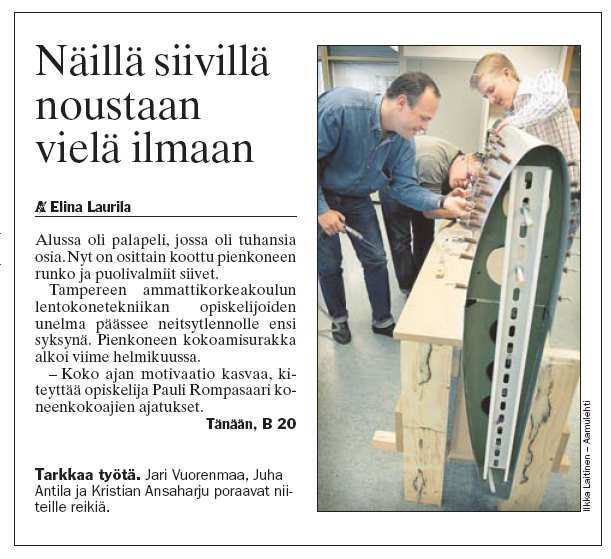
222
223
224
225
226
227
228
229
230
EUROSTAR BASIC KITIN RAKENTAMISEN ORGANISOINTI JA JOHTAMINEN
 TAMPEREEN AMMATTIKORKEAKOULU Kone- ja tuotantotekniikan koulutusohjelma Lentokonetekniikka Tutkintotyö EUROSTAR BASIC KITIN RAKENTAMISEN ORGANISOINTI JA JOHTAMINEN Työn ohjaaja Työn teettäjä Tampere 2005
6a,b 9. 44 2a. 1a 6c 7 8 ULTRAKEVYEN LENTOKONEEN RAKENNE
 1 ULTRAKEVYEN LENTOKONEEN RAKENNE (1a & 1b) siivet (2a & 2b) siivekkeet (3 laskusiivekkeet (4) runko (5) ohjaamo (6a & 6b) pääteline (7) moottori (8) potkuri (9) korkeusvakain (10) korkeusperäsin (11)
LENTOTURVALLISUUSHALLINTO FLIGHT SAFETY AUTHORITY LENTOKELPOISUUSMÄÄRÄYS AIRWORTHINESS DIRECTIVE
 I L M A I L U L A I T O S CIVIL AVIATION ADMINISTRATION PL 50 FIN - 01531 VANTAA, FINLAND Puhelin/Telephone 09-82 771 International + 358 9 82 771 Telefax 09-82 772499 LENTOTURVALLISUUSHALLINTO FLIGHT
MUUTOSTYÖT I L M A I L U L A I T O S TYYPPIHYVÄKSYMÄTTÖMIIN ILMA-ALUKSIIN TEHTÄVÄT MUUTOSTYÖT
 MUUTOSTYÖT TYYPPIHYVÄKSYMÄTTÖMIIN ILMA-ALUKSIIN TEHTÄVÄT MUUTOSTYÖT AIR M5-3 Koe- ja harrasteluokkaan kuuluvan ilma-aluksen lentokelpoisuus ja huolto AIR M5-10 Ultrakevyiden lentokoneiden lentokelpoisuus,
FinFamily PostgreSQL installation ( ) FinFamily PostgreSQL
 FinFamily PostgreSQL") FinFamily PostgreSQL 1 Sisällys / Contents FinFamily PostgreSQL... 1 1. Asenna PostgreSQL tietokanta / Install PostgreSQL database... 3 1.1. PostgreSQL tietokannasta / About the PostgreSQL database...
FinFamily PostgreSQL 1 Sisällys / Contents FinFamily PostgreSQL... 1 1. Asenna PostgreSQL tietokanta / Install PostgreSQL database... 3 1.1. PostgreSQL tietokannasta / About the PostgreSQL database...
Tr af i Im:ffi:#isuusvirasto
 Tr af i Im:ffi:#isuusvirasto Tyyppitodistus Nro FIN / U02B Tämä tyyppitodistus on myönnetty ultrakevyelle lentokoneelle todistukseksi siitä että se täyttää il mai lu mää räyksissä esitetyt vaati mu kset.
SCANFLYERS.COM. Maahantuoja: Scandinavian Flyers PL 10, 01651 Vantaa Puh. 09-849 27 00 Fax. 09-853 14 98 Email: [email protected] www.scanflyers.
 SCANFLYERS.COM Maahantuoja: Scandinavian Flyers PL 10, 01651 Vantaa Puh. 09-849 27 00 Fax. 09-853 14 98 Email: [email protected] www.scanflyers.com MD-3 Rider: Hyvät ominaisuudet, mukava ohjaamo, tyylikästä
ASENNUSOHJE KAMMIOEROTIN JEKA MOOTTORIOHJAIMELLE N 0037.03
 ASENNUSOHJE KAMMIOEROTIN JEKA MOOTTORIOHJAIMELLE N 0037.03 OUTDOOR DISCONNECTOR ISO 9001:2009 ISO 14001:2005 OHSAS 18001:2008 TYPE CUB a) PACKING 9713680 Erotin täydellisenä, sisältää erotinpaketin ja
Tulevat määräysmuutokset
 Tulevat määräysmuutokset Jyrki Laitila Seminaari yleisilmailun lentokelpoisuustehtävissä toimiville henkilöille Vastuullinen liikenne. Rohkeasti yhdessä. EASA mitä muutoksia tulossa L-lupakirja käsitelyty
Ultrakevyen lentokoneen teknilliset tiedot
 FIN/U021 Muutos: 0 Pvm: 25.11.2014 Ultrakevyen lentokoneen teknilliset tiedot Nämä teknilliset tiedot määrittelevät ultrakevyen lentokoneen. Tämä asiakirja on laadittava ja sen on oltava lentokelpoisuustarkastajan
ThermiSol Platina Pi-Ka Asennusohje
 Platina Pi-Ka ThermiSol Platina Pi-Ka essa kerrotaan ThermiSol Platina Kattoelementin käsittelyyn, kiinnitykseen ja työstämiseen liittyviä ohjeita. Platina Pi-Ka 2 1. Elementin käsittely... 3 1.1 Elementtikuorman
HardiePlank kuitusementtipaneelien asennusohje
 HardiePlank kuitusementtipaneelien asennusohje Tuotteet ja tarvikkeet 3 Profiilit 4 Ennen asentamista 5 Asennusperiaatteet 6 Säilyttäminen 7 Työstäminen 8 Kiinnitystarvikkeet 9 Asentaminen 10 Asennustiedot
NÄIN KOKOAT GT-KATOKSEN TARVITTAVAT TYÖKALUT # kaksi 17mm kiintoavainta, rautaviila # kahdet tikkaat # ruuvin väännin/porakone
 GT-KATOS Siisti ympäristöön istuva katos suojaa autot, veneet ja työkoneet ilmansaasteilta, puiden oksilta, lehdiltä ja sateilta. Katoksia voidaan jatkaa 2500mm moduleilla tai tarpeen muuttuessa myös lyhentää
Tuotekortti: Rondo R2
 1 Tuotekortti: Rondo R2 2 TUOTETIEDOT Tuotekoodi Rondo R2-W-Fe RR40-1,0 (tyyppi, hyötyleveys=w, materiaali, väri, ainepaksuus) Pakkaus - Paino 0-2000kg - Levyt pakataan puulavalle muovilla peitettynä ja
On instrument costs in decentralized macroeconomic decision making (Helsingin Kauppakorkeakoulun julkaisuja ; D-31)
") On instrument costs in decentralized macroeconomic decision making (Helsingin Kauppakorkeakoulun julkaisuja ; D-31) Juha Kahkonen Click here if your download doesn"t start automatically On instrument costs
On instrument costs in decentralized macroeconomic decision making (Helsingin Kauppakorkeakoulun julkaisuja ; D-31) Juha Kahkonen Click here if your download doesn"t start automatically On instrument costs
ECVETin soveltuvuus suomalaisiin tutkinnon perusteisiin. Case:Yrittäjyyskurssi matkailualan opiskelijoille englantilaisen opettajan toteuttamana
 ECVETin soveltuvuus suomalaisiin tutkinnon perusteisiin Case:Yrittäjyyskurssi matkailualan opiskelijoille englantilaisen opettajan toteuttamana Taustaa KAO mukana FINECVET-hankeessa, jossa pilotoimme ECVETiä
Installation instruction PEM
 Installation instruction ASENNUSOHJE PEM1032 2010-02 SURGE ARRESTER SET FOR POLE MOUNT TRANSFORMER YLIJÄNNITESUOJASETTI PYLVÄSMUUNTAJALLE ENGLISH SUOMI 2/8 PEM1032 2010-02 ENGLISH GENERAL INFORMATION -
1) Sivulasien asennus Valmistele alumiinilistat (sivu- ja alalistat U-, katonvastainen lista joko F- tai U-profiililla)
 Sivulasien asennus Valmistele alumiinilistat (sivu- ja alalistat U-, katonvastainen lista joko F- tai U-profiililla)") VIHTA-LASISEINÄN ASENNUSOHJE: Käymme tässä asennusohjeessa läpi lasiseinän asennuksen vaihe vaiheelta. Suorittamalla asennustyö huolella tämän ohjeen mukaan lasiseinän asennus sujuu vaivattomasti ja lasiseinän
VIHTA-LASISEINÄN ASENNUSOHJE: Käymme tässä asennusohjeessa läpi lasiseinän asennuksen vaihe vaiheelta. Suorittamalla asennustyö huolella tämän ohjeen mukaan lasiseinän asennus sujuu vaivattomasti ja lasiseinän
EV-97 LENTOKONEEN RAKENTAMISEN KOORDINOINTI
 TAMPEREEN AMMATTIKORKEAKOULU Kone- ja tuotantotekniikan koulutusohjelma Lentokonetekniikka Tutkintotyö EV-97 LENTOKONEEN RAKENTAMISEN KOORDINOINTI Työn ohjaaja Työn teettäjä Tampere 2006 Yliopettaja Heikki
Koskee: Kaikkia Cessna 190- ja 195-lentokoneita lentotuntimäärästä riippumatta.
 M-määräyksen mukainen toimenpide on lentokoneen jatkuvan lentokelpoisuuden edellytyksenä. Suoritettu toimenpide on merkittävä lentokone, moottori- tai potkurikirjaan toimenpiteen laadun mukaan. 242. M-määräys
Ultrakevyen lentokoneen OH-U312 koelento
 Ultrakevyen lentokoneen OH-U312 koelento ref aihe huom 1 trimmi edessä, nopeus Vs, hallintavoima 1.1 trimmi edessä, nopeus Vne, hallintavoima 1.2 trimmi takana, nopeus Vs, hallintavoima 1.3 trimmi takana,
Curriculum. Gym card
 A new school year Curriculum Fast Track Final Grading Gym card TET A new school year Work Ethic Detention Own work Organisation and independence Wilma TMU Support Services Well-Being CURRICULUM FAST TRACK
Santex Huone 81 kiinteällä Santex-katolla ja näkyvällä vesikourulla
 Santex Huone 81 kiinteällä Santex-katolla ja näkyvällä vesikourulla Lue koko asennusohje, ennen kuin aloitat asennuksen. Tämä on näkyvällä vesikourulla varustetun Santex-huoneen 81 ohjeellinen asennusohje.
225 litran kapasiteetilla polymeerisessä syöttölokerossa voi olla jopa 180 kg kuivaa #1 vuorisuolaa, kalsiumkloridia tai muuta jäänestoainetta.
 LP-8 Spreader Paranna liukkaudentorjunnan tehokkuutta Blizzard LP-8 Tailgate -levittimellä, joka on takanäkyvyyden parantamiseksi malliltaan matalaprofiilinen ja jonka kapasiteetti on 225 litraa, jotta
ASENNUS- JA HOITO-OHJE
 03/2005 ASENNUS- JA HOITO-OHJE TREND- Kylpyhuonekalusteet Sisällysluettelo TREND-kylpyhuonekalusteet Asennuslistan mittatiedot laatikollisille TREND alakaapeille 600/900/1200x500x485 mm 2 Kaapin asennus
Suojuspelti, moottorin alle
 Installation instructions, accessories Ohje nro 31269439 Versio 1.2 Osa nro 31269431, 31269432, 31269433, 31269434 Suojuspelti, moottorin alle IMG-328898 Volvo Car Corporation Suojuspelti, moottorin alle-
AUTOTALLI KÄYTTÖOHJE
 AUTOTALLI KÄYTTÖOHJE ENNEN KUIN ALOITAT Ennen kuin aloitat asennuksen, ota selvää paikallisilta viranomaisilta, tarvitseeko autotalli rakennusluvan. Lue käyttöohje huolellisesti ja noudata annettuja ohjeita.
Baby-Merc lastenvaunut Käyttöohjeet
 Baby-Merc lastenvaunut Käyttöohjeet Kiitos, että olet valinnut tuotteemme! Olemme varmoja, että tulet olemaan tyytyväinen lastenvaunuihimme. Ennen kuin käytät lastenrattaita, on erittäin suositeltavaa
AKKREDITOITU TARKASTUSLAITOS ACCREDITED INSPECTION BODY DEKRA INSPECTION OY
 I047/M02/2016 Liite 1 / Appendix 1 Sivu / Page 1(6) AKKREDITOITU TARKASTUSLAITOS ACCREDITED INSPECTION BODY DEKRA INSPECTION OY Tunnus Code Tarkastuslaitos Inspection body Osoite Address www www I047 DEKRA
TUOTEKORTTI: RONDO L1
 TUOTEKORTTI: RONDO L1 Tuotekoodi: Rondo L1-W-Fe RR40-1,0 (tyyppi, hyötyleveys=w, materiaali, väri, ainepaksuus) kuva 1: Rondo L1 seinäliittymä, pystyleikkaus TUOTEKUVAUS Käyttötarkoitus Raaka-aineet Värit
FI.LPINST.101104 ASENNUSOHJE GOLD LP. Asiakirjan alkuperäiskieli on ruotsi. Oikeus muutoksiin pidätetään. www.swegon.fi 1
 ASENNUSOHJE GOLD LP Asiakirjan alkuperäiskieli on ruotsi Oikeus muutoksiin pidätetään. www.swegon.fi 1 1. ASENNUS 1.4 Koneen asennus 1.1 Yleistä Henkilöstön on tutustuttava näihin ohjeisiin ennen koneelle
Ultrakevyen lentokoneen teknilliset tiedot
 Ultrakevyen lentokoneen teknilliset tiedot Nämä teknilliset tiedot määrittelevät ultrakevyen lentokoneen. Tämä asiakirja on laadittava ja sen on oltava lentokelpoisuustarkastajan hyväksymä ennen kuin ultrakevyelle
Capacity Utilization
 Capacity Utilization Tim Schöneberg 28th November Agenda Introduction Fixed and variable input ressources Technical capacity utilization Price based capacity utilization measure Long run and short run
C++ Ohjelmoijan käsikirja. Johdanto
 Johdanto C++ Ohjelmoijan käsikirja Johdanto Tervetuloa Inside C++-kirjan pariin. Tämä on opaskirja standardi C++:n käyttöön. Käsittelemme kirjassa kaikki syntaksin, kieliopin, olio-ohjelmoinnin ja standardikirjastojen
Ruuviliitokset. Yleistä tietoa ruuviliitoksista. Kitkaliitoksen ja muotoliitoksen yhdistelmä
 Yleistä tietoa ruuviliitoksista Yleistä tietoa ruuviliitoksista Ruuviliitokset voidaan tehdä kitkaliitoksina, muotoliitoksina tai näiden kahden yhdistelmänä. Kitkaliitos vaatii noin 10 kertaa enemmän ruuveja
On instrument costs in decentralized macroeconomic decision making (Helsingin Kauppakorkeakoulun julkaisuja ; D-31)
") On instrument costs in decentralized macroeconomic decision making (Helsingin Kauppakorkeakoulun julkaisuja ; D-31) Juha Kahkonen Click here if your download doesn"t start automatically On instrument costs
On instrument costs in decentralized macroeconomic decision making (Helsingin Kauppakorkeakoulun julkaisuja ; D-31) Juha Kahkonen Click here if your download doesn"t start automatically On instrument costs
Julkaisun laji Opinnäytetyö. Sivumäärä 43
 OPINNÄYTETYÖN KUVAILULEHTI Tekijä(t) SUKUNIMI, Etunimi ISOVIITA, Ilari LEHTONEN, Joni PELTOKANGAS, Johanna Työn nimi Julkaisun laji Opinnäytetyö Sivumäärä 43 Luottamuksellisuus ( ) saakka Päivämäärä 12.08.2010
Lapuan myöntämä EU tuki SOLUTION asuinalueille omakoti- tai rivitaloa rakentaville
 Lapuan myöntämä EU tuki SOLUTION asuinalueille omakoti- tai rivitaloa rakentaville Pakollinen liite rakennustyön tarkastusasiakirjaan ja toiseen hakuvaiheeseen / Compulsory supplement the construction
Urajärven kartanomuseo
 Urajärven kartanomuseo Hugon huoneen ikkunan uuden karmin teko ja olemassa olevien pokien kunnostustyö 7-8/2013 Karmi Karmi oli huonokuntoinen ja aiemmissa korjauksissa sitä oli kaltoin kohdeltu. Karmia
HUOMIO! YLEISIÄ VAROITUKSIA!
 Teräspalo-luukkujen FQ HUOMIO! YLEISIÄ VAROITUKSIA! Tämän luukun asennuksessa, käytössä ja kunnossapidossa tulee noudattaa useita varotoimia. Turvallisuussyistä kannattaa huomioida alla mainitut varoitukset
Pienoiskasvihuone. esimerkki ryhmäprojektista koululle tai koulun ulkopuoliselle asiakkaalle.
 Pienoiskasvihuone esimerkki ryhmäprojektista koululle tai koulun ulkopuoliselle asiakkaalle. Raportti teknisen työn erikoistumisopintojen soveltavasta työstä. Antti Laakkonen 27.4.1992 1. Työn kuvaus Esimerkkityöksi
Hydraulinen vetokoukku
 Hydraulinen vetokoukku Tekniset tiedot Traktorin mallisarjat Paino Vetokuulan kanssa Paino vetonupin kanssa Paino vetopuomin kanssa Nostoalue Maavara vetoasennossa (riippuu rengaskoosta) 3/2005 jälkeen
AUTORENGASLIIKE RENGASKORJAAMO A. IHALAINEN
 UNIONINKATU AUTORENGASLIIKE RENGASKORJAAMO A. IHALAINEN - HELSINKI 41 PUHELIMET 29790 37523 Suuri, ajanmukaisella koneistolla varustettu autorenkaiden vulkanoimislaitos AUTORENKAIDEN VULKANOINTI on maassamme,
This notice in TED website:
 1 / 6 This notice in TED website: http://ted.europa.eu/udl?uri=ted:notice:408042-2017:text:en:html -Vantaa: Health and social work services 2017/S 198-408042 Social and other specific services public contracts
TH-FLWBL läpivientianturin asennusohjeet. TH-FLWBL on 11, 200kHz anturi joka on suunniteltu Lowrance laitteisiin jotka käyttävät sinistä liitintä.
 TH-FLWBL läpivientianturin asennusohjeet TH-FLWBL on 11, 200kHz anturi joka on suunniteltu Lowrance laitteisiin jotka käyttävät sinistä liitintä. Lue ohjeet huolella ennenkuin asennat anturin. Muista että
Lab SBS3.FARM_Hyper-V - Navigating a SharePoint site
 Lab SBS3.FARM_Hyper-V - Navigating a SharePoint site Note! Before starting download and install a fresh version of OfficeProfessionalPlus_x64_en-us. The instructions are in the beginning of the exercise.
Linnunpöntön kokoamisohje
 Linnunpöntön kokoamisohje Kiitämme Sinua leijonien rakennussarjan hankkimisesta. Kun seuraat kokoamisen työvaiheittaisia ohjeita huolellisesti, olet saanut rakennettua toimivan kodin linnulle. Rakennussarjojen
TYÖLAITTEET KA250/400 KA300/450 KERÄÄVÄ AURAN KÄYTTÖOHJE. Mateko Oy Punasillantie 6 40950 Muurame PUH. 014 3349 400 FAX 014 2440 61
 TYÖLAITTEET KA250/400 KA300/450 KERÄÄVÄ AURAN KÄYTTÖOHJE Mateko Oy Punasillantie 6 40950 Muurame PUH. 014 3349 400 FAX 014 2440 61 EY-Vaatimustenmukaisuusvakuutus koneesta Lapinlahden levypalvelu Oy vakuuttaa,
Finnforest Terassin kokoamisohje Terassi 10
 Finnforest Terassin kokoamisohje Terassi 10 Terassin kokoaminen ja perustaminen Terassi on tarkoitettu koottavaksi valmiiksi pohjustetulle ja tasatulle maalle. Perustamisessa on otettava huomioon mahdollinen
Tekninen työ. Aihepiirityöskentely: KASETTITELINE. Helsingin yliopisto opettajankoulutuslaitos syksy 1994 Jukka Kasurinen
 Tekninen työ Aihepiirityöskentely: KASETTITELINE Helsingin yliopisto opettajankoulutuslaitos syksy 1994 Jukka Kasurinen 1. MOTIVOINTI Aluksi keskustellaan oppilaiden kanssa, mitä erilaisia kasetteja he
Silent Gliss 9020/21, 9040/41 ja 5091 moottorit. Uusi moottorisukupolvi
 Silent Gliss 9020/21, 9040/41 ja 5091 moottorit Uusi moottorisukupolvi Elämää helpottavia innovaatioita Silent Glissillä on yli 40 vuoden kokemus sähkötoimisista verhokiskoista. Toimme ensimmäisenä markkinoille
ROCKFON SYSTEM G DIRECT
 Järjestelmän kuvaus: ROCKFON SYSTEM G DIRECT Suoraan asennettava järjestelmä Nopea ja tehokas asennusprosessi Oikea valinta mataliin huoneisiin Tyylikäs ja yhtenäinen ilme alakattoon G 300 mm ROCKFON SYSTEM
Information on preparing Presentation
 Information on preparing Presentation Seminar on big data management Lecturer: Spring 2017 20.1.2017 1 Agenda Hints and tips on giving a good presentation Watch two videos and discussion 22.1.2017 2 Goals
Asiantuntijasi rikkojen torjunnassa
 Asiantuntijasi rikkojen torjunnassa Kun viljelykasvien valikoima on laaja, kasvit ovat eri kasvuasteilla ja rivivälit erilevyisiä, ei oikean koneen löytäminen ole helppoa. Usein huomaat etteivät valmistajien
PART-21. Viimeinen päivitys Last Update
 PART-21 Alla olevat lupaotteet sisältävät tiedot Part-21 organisaatioista, joilla on voimassa oleva EASAn määräyksiin perustuva Liikenteen turvallisuusvirasto Trafi:n myöntämä toimilupa. Tiedot ovat ohjeellisia.
Apuja ohjelmointiin» Yleisiä virheitä
 Apuja ohjelmointiin» Yleisiä virheitä Ohjelmaa kirjoittaessasi saattaa Visual Studio ilmoittaa monenlaisista virheistä "punakynällä". Usein tämä johtuu vain siitä, että virheitä näytetään vaikket olisi
LYTH-CONS CONSISTENCY TRANSMITTER
 LYTH-CONS CONSISTENCY TRANSMITTER LYTH-INSTRUMENT OY has generate new consistency transmitter with blade-system to meet high technical requirements in Pulp&Paper industries. Insurmountable advantages are
ILMAILUMÄÄRÄYS AIR M1-2
 ILMAILUMÄÄRÄYS AIR M1-2 muutos 1 6.2.1996 PL 50, 01531 VANTAA, FINLAND, Tel. 358 (0)9 82 771, Fax 358 (0)9 82 772499 www.lentoturvallisuushallinto.fi ILMA-ALUSTEN KANSALLISUUS- JA REKISTERITUNNUKSET Tämä
TIEKE Verkottaja Service Tools for electronic data interchange utilizers. Heikki Laaksamo
 TIEKE Verkottaja Service Tools for electronic data interchange utilizers Heikki Laaksamo TIEKE Finnish Information Society Development Centre (TIEKE Tietoyhteiskunnan kehittämiskeskus ry) TIEKE is a neutral,
TAMPEREEN AMMATTIKORKEAKOULU Kone- ja tuotantotekniikan koulutusohjelma Lentokonetekniikka. Tutkintotyö. Aki Penttinen
 TAMPEREEN AMMATTIKORKEAKOULU Kone- ja tuotantotekniikan koulutusohjelma Lentokonetekniikka Tutkintotyö Aki Penttinen Eurostar lentokoneen ohjaus ja vakavuus Eurostar Aircraft control and stability Työn
Harrasteilmailun ilma-alusten punnitus. 17.4.2013 Markku Hiedanpää
 Harrasteilmailun ilma-alusten punnitus 17.4.2013 Markku Hiedanpää Miksi ilma-aluksia punnitaan Jotta voidaan määritellä onko ilma-alus tyyppihyväksymistodistuksen (so. koelennoilla tositettujen), tyyppitodistuksen
IRROITA SYDÄN. Pulmapeli. BLÄUER 2003 versio ja laita takaisin jos osaat...
 IRROITA SYDÄN ja laita takaisin jos osaat... Pulmapeli BLÄUER 2003 versio 1.05 WWW.KASITYO.COM 1. TYÖN TAVOITE Valmistamme metallisen pulmapelin, jossa tarkoituksena on ottaa sydän pois ja laittaa se takaisin
WEBER.VETONIT TUOTTEET JA TYCROC TWP RAKENNUSLEVYT SEINÄÄN JA LATTIAAN
 WEBER.VETONIT TUOTTEET JA TYCROC TWP RAKENNUSLEVYT SEINÄÄN JA LATTIAAN Ennen Tycroc TWP rakennuslevyjen asennusta täytyy varmistaa, että alusta on kuiva, luja, jäykkä ja vakaa sekä puhdas pölystä, öljystä,
Asennusohje LASISEINÄ
 Asennusohje LASISEINÄ Käymme tässä asennusohjeessa läpi lasiseinän asennuksen vaihe vaiheelta. Suorittamalla asennustyö huolella tämän ohjeen mukaan lasiseinän asennus sujuu vaivattomasti ja taataan lasiseinän
Elektra V ... 13 ... 7... 9 GB... 11 NO ... 21 ... 15 ... 17 DE... 19 PL ... 23 ... 27 ... 25
 SE... 7... 9 GB... 11 NO FR... 13 RU... 15... 17 DE... 19 PL FI... 21 NL... 23 ES... 25 IT... 27 ELV3333, ELV3344, ELV5333, ELV6344 375 300 340 min 300 mm c-c 277 24 9 16 min 300 mm min 500 mm Fig. 1 10
Alkusanat: Tarvittavat työkalut ja tarvikkeet: Martti Myllyntaus Vertical YAK 54 30e ARF 2.9.2009. Rakennusajankohta: 26.8 2.9.
 Rakennusajankohta: 26.8 2.9.2009 Rakennusaika: n.7 tuntia + painopisteen säätö Alkusanat: Verticalin ARF sarjasta rakensin tämän mallin viimeisenä. Alkutarkastelun jälkeen tämä on sattumoisin ollut hyvä
ASENNUSOHJE DYNAAMINEN TRIMMIOHJAUSJÄRJESTELMÄ S-SARJA
 ASENNUSOHJE DYNAAMINEN TRIMMIOHJAUSJÄRJESTELMÄ S-SARJA TYÖKALUT Porakone Poranterät Reikäsaha Ruuvin kannat Ø 2,5 mm (3/32 ) Ø 3 mm (1/8 ) Ø 19 mm (3/4 ) Ø 76 mm (3 ) T10 T20 Ø 3,5 mm (9/64 ) T25 Ø 4 mm
HUOMAA! ON TÄRKEÄÄ, ETTÄ VÄLIT TIIVISTETÄÄN SILIKONILLA. MUUTEN VESI VOI TUNKEUTUA RAKENTEISIIN. Asennusohjeet Vinter-liukuovet
 Lue asennusohjeet läpi ennen töiden aloittamista. Jotta kehykset eivät vaurioituisi kuljetuksen aikana, ne toimitetaan osina. Olemme kuitenkin testanneet koko järjestelmän paneeleineen ennen toimitusta
ASENNUSOHJE MINSTER JA TURMALIN
 Turmalin-savikattotiili Minster-betonikattotiili ASENNUSOHJE Päivitetty 14.12.2012 Tämä korvaa aiemmat asennusohjeet Puh. +358 9 2533 7200 ~ Faksi +358 9 2533 7311 ~ www.monier.fi Sivu 1 / 9 Alkulause
You can check above like this: Start->Control Panel->Programs->find if Microsoft Lync or Microsoft Lync Attendeed is listed
 Online Meeting Guest Online Meeting for Guest Participant Lync Attendee Installation Online kokous vierailevalle osallistujalle Lync Attendee Asennus www.ruukki.com Overview Before you can join to Ruukki
Sami Hirvonen. Ulkoasut Media Works sivustolle
 Metropolia ammattikorkeakoulu Mediatekniikan koulutusohjelma VBP07S Sami Hirvonen Ulkoasut Media Works sivustolle Loppuraportti 14.10.2010 Visuaalinen suunnittelu 2 Sisällys 1 Johdanto 3 2 Oppimisteknologiat
BETRIEBSANLEITUNG RESERVETEILKATALOG OPERATOR S INSTRUCTION BOOK SPARE PARTS LIST
 VÄLI99KA BETRIEBSANLEITUNG RESERVETEILKATALOG OPERATOR S INSTRUCTION BOOK SPARE PARTS LIST 62375 YLIHÄRMÄ FINLAND TEL. +358-(0)6-4835111 FAX +358-(0)6-4846401 Suomi 2 Arvoisa Asiakas Kiitämme osoittamastanne
MUSEOT KULTTUURIPALVELUINA
 Elina Arola MUSEOT KULTTUURIPALVELUINA Tutkimuskohteena Mikkelin museot Opinnäytetyö Kulttuuripalvelujen koulutusohjelma Marraskuu 2005 KUVAILULEHTI Opinnäytetyön päivämäärä 25.11.2005 Tekijä(t) Elina
AKKREDITOITU TARKASTUSLAITOS ACCREDITED INSPECTION BODY INSPECTA TARKASTUS OY
 I001 Liite 1.12 / Appendix 1.12 Sivu / Page 1(6) Ilmoitettu laitos, Notified body, AKKREDITOITU TARKASTUSLAITOS ACCREDITED INSPECTION BODY INSPECTA TARKASTUS OY Tunnus Code Yksikkö tai toimintoala Department
Käämikytkimet, tyyppiä UB moottoriohjaimilla, tyyppiä BUE ja BUL. Asennus- ja käyttöönotto-ohjeet
 Käämikytkimet, tyyppiä UB moottoriohjaimilla, tyyppiä BUE ja BUL Asennus- ja käyttöönotto-ohjeet Tätä ohjetta ei saa kopioida ilman meidän kirjallista lupaamme eikä sisältöä saa luovuttaa kolmannelle osapuolelle
Fonte 16045SAVA 16045VAVA 16045SAVA 16045VAVA ASENNUSOHJE MONTERINGSANVISNING ASSEMBLY INSTRUCTIONS K16045VAK2 K16045SAK1 K16045K3 K16045K3
 Fonte 16045SAVA 16045VAVA ASENNUSOHJE MONTERINGSANVISNING ASSEMBLY INSTRUCTIONS 16045SAVA K16045SAK1 K16045VAK2 K16045K3 16045VAVA K16045VAK1 K16045VAK2 K16045K3 1 2 900167 LE22SWL003 LE22VWL003 LE18VWL001
Suomalaista siviili-ilma-alusten rakentamista vuodesta 1949
 Suomalaista siviili-ilma-alusten rakentamista vuodesta 1949 Markku Hiedanpää 1960 Hämeenlinna Ilmailukerho ry 1963 PIK-16 Vasama, KK Lehtovaara Oy 1965-67 KK-1 Utu, Oy Fibera Ab 1970-1973 PIK-19 Muhinu,
KOKOONTAITETTAVA HENKARI
 VAASAN AMMATTIKORKEAKOULU Ryhmä 3 Olli Eronen Tomi Blomback Jaakko Etelämäki KOKOONTAITETTAVA HENKARI 3D-Tuoteprojekti Simultaanisuunnittelu Tekniikka ja liikenne 2005 2 1. SISÄLLYS 2. RYHMÄESITTELY 3
Mark Summary Form. Tulospalvelu. Competitor No Competitor Name Member
 Summary Form Skill Number 605 Skill Levy ja hitsaus Criterion Criterion Description s Day 1 Day 2 Day 3 Day 4 Award A B C D Puijon hyppyrimäen valmistaminen. Piir n:o 2011300, 2011400, 2011700, 2011600,
Biojätteen keruu QuattroSelect - monilokerojärjestelmällä. 21.10.2015 Tiila Korhonen SUEZ
 Biojätteen keruu QuattroSelect - monilokerojärjestelmällä 21.10.2015 Tiila Korhonen SUEZ Agenda 1 SITA Suomi on SUEZ 2 QS, mikä se on? 3 QS maailmalla 4 QS Suomessa 5 QS Vaasassa SITA Suomi Oy ja kaikki
Asennusja käyttöohje. Agrosec Optivol M11. 408107 (fi)
") Asennusja käyttöohje Agrosec Optivol M11 408107 (fi) ANTTI-TEOLLISUUS OY Koskentie 89 25340 Kanunki, Salo Puh. +358 2 774 4700 Fax +358 2 774 4777 E-mail: [email protected] www.antti-teollisuus.fi
Asennusja käyttöohje Agrosec Optivol M11 408107 (fi) ANTTI-TEOLLISUUS OY Koskentie 89 25340 Kanunki, Salo Puh. +358 2 774 4700 Fax +358 2 774 4777 E-mail: [email protected] www.antti-teollisuus.fi
VARASTOTELTTA KOKOAMISOHJE L3L4
 VARASTOTELTTA KOKOAMISOHJE L3L4 0 TIEDOT Leveys: 4 m Pituus: 8 m Korkeus: 4,2 m TÄRKEÄÄ LUE OHJE ENNEN KOKOAMISTA Puutteellinen alueen valmistelu, kokoaminen ja ylläpito voivat vaikuttaa takuuseen ja johtaa
AKKREDITOITU TARKASTUSLAITOS ACCREDITED INSPECTION BODY TEOLLISUUDEN VOIMA OYJ, TVO:N TARKASTUSLAITOS TVO USER INSPECTORATE
 I024/M09/2016 Liite 1 / Appendix 1 Sivu / Page 1(7) AKKREDITOITU TARKASTUSLAITOS ACCREDITED INSPECTION BODY TEOLLISUUDEN VOIMA OYJ, TVO:N TARKASTUSLAITOS TVO USER INSPECTORATE Tunnus Code Tarkastuslaitos
4 m karjateltta KOKOAMISOHJE. MITAT: L4xP4xK3,2 ml5
 4 m karjateltta KOKOAMISOHJE MITAT: L4xP4xK3,2 ml5 1 ERITTELY Leveys: 4 m Pituus: 4 m Korkeus: 3,2 m TÄRKEÄÄ LUE OHJE ENNEN KOKOAMISTA Puutteellinen alueen valmistelu, kokoaminen ja ylläpito voivat vaikuttaa
MACCO BF Haarukkavaunu KÄYTTÖOHJEET. Oy Machine Tool Co
 MACCO BF Haarukkavaunu KÄYTTÖOHJEET Oy Machine Tool Co 1. Käyttökohteet Käsikäyttöinen MACCO BF -haarukkavaunu on matalarakenteinen, vain kuormalavalla olevan, kovilla pinnoilla liikuteltavan tavaran siirtelyyn
Lämpöputkilämmönsiirtimet HPHE
 Lämpöputkilämmönsiirtimet HPHE LÄMMÖNTALTEENOTTO Lämmöntalteenotto kuumista usein likaisista ja pölyisistä kaasuista tarjoaa erinomaisen mahdollisuuden energiansäästöön ja hiilidioksidipäästöjen vähentämiseen
Hankintailmoitus: Pohjois-Savon sairaanhoitopiirin kuntayhtymä/kiinteistöyksikkö : Puijon sairaalan Pääaula-alueen uudistus, Sähköurakka
 Finland Tender Hankintailmoitus: Pohjois-Savon sairaanhoitopiirin kuntayhtymä/kiinteistöyksikkö : Puijon sairaalan Pääaula-alueen uudistus, Sähköurakka Tarjoukset 6.5.2011 klo 15.00 mennessä osoitteeseen:
WWW.LAMOX.FI [email protected]
 1 Perinteinen valesokkelirakenne Termotuote korjattu rakenne Asennus 2 Ennen työn aloittamista on aina tarkistettava päivitetyt viimeisimmät suunnitteluohjeet valmistajan kotisivuilta. Eristämisessä on
JUSSI-parviportaiden kokoamisohjeet
 MSJ-WOOD OY JUSSI-parviportaiden kokoamisohjeet Kokoamisohjeet suorille parviportaille MSJ-Wood 15.5.2010 www.jussi-portaat.fi Teit erinomaisen valinnan ostaessasi JUSSI-portaan. Ohjeen sisältö: Sisällysluettelo
Installation instruction PEM
 Installation instruction ASENNUSOHJE PEM1031 2010-04 CURRENT LIMITING DEVICE FOR POLE MOUNT TRANSFORMER VIRTAA RAJOITTAVA SUOJA PYLVÄSMUUNTAJALLE ENGLISH SUOMI 75 2/8 PEM1031 2010-04 ENGLISH GENERAL INFORMATION
1. Alkusanat. 2. Käyttötarkoitus. 3. Turvallisuusohjeet
 Minikaivurit Tuotenumero Avant 200-sarjaan A33153 Tuotenumero Avant 500- ja 600-sarjaan 250 mm kauhalla A32393 Tuotenumero Avant 500- ja 600-sarjaan 400 mm kauhalla A32394 2 1. Alkusanat Avant Tecno Oy
Salasanan vaihto uuteen / How to change password
 Salasanan vaihto uuteen / How to change password Sisällys Salasanakäytäntö / Password policy... 2 Salasanan vaihto verkkosivulla / Change password on website... 3 Salasanan vaihto matkapuhelimella / Change
Ultrakevyen lentokoneen teknilliset tiedot
 FIN/U017 Muutos: 0 Pvm: 25.9.2014 Ultrakevyen lentokoneen teknilliset tiedot Nämä teknilliset tiedot määrittelevät ultrakevyen lentokoneen. Tämä asiakirja on laadittava ja sen on oltava lentokelpoisuustarkastajan
Kiinteiden ja liukukattojen yhdistelmä.
 Kiinteiden ja liukukattojen yhdistelmä. Tarkasta aina ennen asennuksen aloittamista, että toimitus sisältää oikean määrän tarvikkeita. Katso tarvikeluettelo seuraavalta sivulta. HUOM! Ruuvit ovat Torx-ruuveja.
TW-LTE 4G/3G. USB-modeemi (USB 2.0)
") TW-LTE 4G/3G USB-modeemi (USB 2.0) Tiedonsiirtonopeus: 100 Mbps/50 Mbps LTE: 1800/2100/2600 MHz GSM/GPRS/EDGE: 850/900/1800/1900 MHz UMTS: 900/2100 MHz Pikaohje (Finnish) CE Käyttöönotto- ohje SIM- kortin
TW-LTE 4G/3G USB-modeemi (USB 2.0) Tiedonsiirtonopeus: 100 Mbps/50 Mbps LTE: 1800/2100/2600 MHz GSM/GPRS/EDGE: 850/900/1800/1900 MHz UMTS: 900/2100 MHz Pikaohje (Finnish) CE Käyttöönotto- ohje SIM- kortin
Tietorakenteet ja algoritmit
 Tietorakenteet ja algoritmit Taulukon edut Taulukon haitat Taulukon haittojen välttäminen Dynaamisesti linkattu lista Linkatun listan solmun määrittelytavat Lineaarisen listan toteutus dynaamisesti linkattuna
anna minun kertoa let me tell you
 anna minun kertoa let me tell you anna minun kertoa I OSA 1. Anna minun kertoa sinulle mitä oli. Tiedän että osaan. Kykenen siihen. Teen nyt niin. Minulla on oikeus. Sanani voivat olla puutteellisia mutta
Choose Finland-Helsinki Valitse Finland-Helsinki
 Write down the Temporary Application ID. If you do not manage to complete the form you can continue where you stopped with this ID no. Muista Temporary Application ID. Jos et onnistu täyttää lomake loppuun
USB-siirto-ohjelman ja ajurin asentaminen
 1 (8) USB-siirto-ohjelman ja ajurin asentaminen Ladattuasi Handan CV-7700 PVR laitteen USB-siirto-ohjelman Welhon internet- sivuilta, asenna ohjelma alla olevien ohjeiden mukaan. Siirto-ohjelman asennus