RENGASKONE TIRE CHANGER ST-1231
|
|
|
- Saara Penttilä
- 7 vuotta sitten
- Katselukertoja:
Transkriptio

1 RENGASKONE TIRE CHANGER ST-1231 KÄYTTÖOHJE USER S MANUAL Lue tämä käyttöohje huolellisesti kokonaisuudessaan ennen koneen asennusta ja käyttöä. Read the entire manual carefully and completely before installation or operation of the machine.
2 Sisällys 1. Esittely Turvallisuusohjeet Varoitustarrat Tekniset tiedot Kuljetus Pakkauksen purkaminen Työskentelyalueen vaatimukset Tuotekaavio Asennus Paineilmakytkentä Sähkökytkentä Toiminnot (kts. 8. Tuotekaavio) Esivalmistelut Palteen irrotus Renkaan kiinnitys asennuspöytään Renkaan irrotus vanteelta Renkaan asennus vanteelle Renkaan täyttäminen Rengaskoneen siirtäminen ja varastointi Huolto Vianmääritys Rengaskoneen räjäytyskuvat Varaosaluettelo ~ 2 ~
3 Rengaskone Lue käyttöohje huolellisesti läpi ennen koneen käytön aloittamista. Säilytä käyttöohje tulevaa tarvetta varten. 1. Esittely Käyttötarkoitus: Puoliautomaattinen rengaskone on suunniteltu renkaiden asennukseen vanteille ja pois vanteilta Huom. Rengaskonetta saa käyttää vain sille suunniteltuun tarkoitukseen. Koneen valmistaja ja maahantuoja eivät ole vastuussa väärinkäytöstä aiheutuneista vahingoista. 2. Turvallisuusohjeet Konetta saa käyttää ainoastaan koneen käyttöön perehtynyt henkilö. Koneen väärinkäyttö sekä koneen tai sen osien muuttaminen vapauttavat valmistajan vastuusta mahdollisesti aiheutuneisiin vahinkoihin. Takuuaika on yksi vuosi. 3. Varoitustarrat 01 Älä laita käsiä asennuspään alle koneen toiminnan aikana 02 Älä laita käsiä leukojen väliin koneen toiminnan aikana 03 Älä laita käsiä vanteen palteelle kun rengasta irrotetaan vanteelta 04 Varmista että kone on asiallisesti maadoitettu 05 Älä laita jalkoja palteenirrottimen ja koneen väliin toiminnan aikana 06 Turvallisuusohjeet 07 Ole huolellinen paineilmakompressorin kanssa ~ 3 ~
4 4. Tekniset tiedot Vanteen kiinnitys ulkopuolelta Vanteen kiinnitys sisäpuolelta Renkaan maksimihalkaisija 1043mm (45 ) Renkaan maksimileveys 406mm (16 ) Palteenirrottimen voima paineella 1 Mpa 2500kg Maksimikäyttöpaine 8-10bar Jännitelähde 380V Moottorin teho 0.75 kw Maksimivääntövoima (asennuspöytä) 1078 Nm (110Kg.m) Ulkomitat 113 x 90 x 103cm Melutaso <75 db 5. Kuljetus Siirrä rengaskone trukilla pohjasta nostamalla (Kuva 1). Kuva 1 6. Pakkauksen purkaminen Irrota niitit, joilla pahvi on kiinnitetty kuormalavaan. pura pahviset ja muoviset pakkausosat. Kun tuote on purettu pakkauksesta, tarkista ettei mukana ole näkyvästi vioittuneita osia. 7. Työskentelyalueen vaatimukset Työskentelyalueen on noudatettava turvallisuusohjeita. Liitä rengaskone sähköverkkoon ja paineilmalähteeseen käyttöohjeen mukaisesti. Työtilassa on oltava hyvä ilmastointi. Rengaskoneen ympärillä on oltava etäisyyttä seiniin Kuvan 2 mukaisesti, jotta kone mahtuu toimimaan hyvin. Kone on suojattava sateelta ja auringonvalolta. Kuva 2 ~ 4 ~
5 8. Tuotekaavio Rengaskone PL-1231 A Lukituskahva I Palteenirrottimen poljin B Asennuspään varsi J Kääntöpoljin C Asennuspää K Rengasrauta D Kiinnitysleuka L Kumipehmike E Asennuspöytä M Palteenirrotin G Kallistuspoljin O Pylväs H Kiinnitysleukojen poljin P Vaakasuora varsi ~ 5 ~
6 9. Asennus 1. Kiinnitä pylväs (osa 1 Kuvassa 3) rungon (9) päälle neljällä pultilla. Pujota ilmaletku (6) pylväässä olevan reiän läpi. Kiristä neljä lukkomutteria. 2. Kiinnitä pultti (13) paikoilleen pylvääseen. Liitä kallistussylinterin tappi (7) ja kiristä lukkomutterilla (12). 3. Aukaise vasemman kannen (10) kaksi ruuvia (11) ja poista kansi. Liitä ilmaletku (8) pylväästä 5-haaraiseen venttiiliin. 4. Kiinnitä muovisuoja (5) kahdella ruuvilla (4). 5. Kiinnitä pienempi muovisuoja (3) pylvääseen ruuvilla (2). 10. Paineilmakytkentä 1. Paina poljin alas varmistaaksesi, etteivät asennuspöydän kiinnitysleuat avaudu odottamatta. 2. Liitä rengaskone paineilmaverkkoon ilmaletkulla (sisähalkaisija 7-8 mm). Ilmanpaineen on oltava 8-10 bar. Ilmanpaine ei saa ylittää 10 bar. 3. Liitä rengaskone paineilmaverkkoon koneen takana olevalla liittimellä. Kuva Sähkökytkentä Huom. Varmista, että jännitelähde vastaa koneen teknisiä tietoja. Yhdistä sähköliitäntä maadoitettuun pistorasiaan. Varmista, että käytettävissä on vähintään 30 A virta. 12. Toiminnot (kts. 8. Tuotekaavio) Lukituskahvalla (A) voidaan lukita asennuspään varsi (B) ja vaakasuora varsi (P). Asennuspäätä (C) voidaan automaattisesti nostaa noin 2-3 mm lukittuna. Kallistuspolkimella (G) voidaan kallistaa pylvästä (O). Kiinnistysleukojen polkimella (H) voidaan avata ja sulkea asennuspöydän kiinnitysleuat (D). Palteenirrottimen polkimella (I) voidaan ohjata palteenirrotinta (M). Kääntöpoljin (J) voidaan kääntää asennuspöytää (E) myötä- tai vastapäivään. Rengaskoneen toiminta koostuu kolmesta osasta: 1) Palteen irrotus 2) Renkaan irrotus vanteelta 3) Renkaan asennus vanteelle Varoitus: Älä käytä löysiä vaatteita konetta käyttäessäsi. Käytä suojalaseja, - hanskoja sekä pitäviä kenkiä. Ennen toiminnon suorittamista, varmista, että rengas on tyhjennetty ilmasta ja poista kaikki rengaspainot vanteesta. Kuva 4 Kuva 5 ~ 6 ~
7 13. Esivalmistelut Tarkista, että rengaskone toimii oikein kytkentöjen jälkeen: 1. Paina kääntöpoljin alas. Asennuspöydän tulisi kääntyä myötäpäivään. 2. Pidä kiinni palteenirrottimesta ja paina palteenirrottimen poljinta. Palteenirrotin sulkeutuu. 3. Paina kiinnitysleukojen poljin pohjaan avataksesi kiinnitysleuat kokonaan. Painamalla uudestaan leuat vapautuvat. Toistamalla painamista kiinnitysleuat sulkeutuvat. 4. Paina kallistuspoljinta. Pylväs kallistuu taaksepäin alkuasentoon. Painamalla uudestaan pylväs kallistuu takaisin työskentelyasentoon. 5. Paina lukituskahvan painiketta. Asennuspään varsi ja vaakasuora varsi lukittuvat asentoonsa. Samaan aikaan asennuspää nousee automaattisesti 2-3 mm vanteen reunasta. Painamalla painiketta uudestaan varret vapautuvat lukituksesta. 14. Palteen irrotus Tyhjennä rengas ilmasta kokonaan. Aseta rengas kumipehmikettä vasten, aseta palteenirrottimen työpää palletta vasten noin 10 mm vanteen reunasta (Kuva 6). Paina palteenirrottimen poljinta saadaksesi palteenirrottimen painamaan palteen alas. Käännä rengasta toistaen edellinen toiminto vanteen ympäri, kunnes palteen irrotus on suoritettu. 15. Renkaan kiinnitys asennuspöytään Huom. Varmista, että rengas on tyhjennetty ilmasta ja poista kaikki rengaspainot vanteesta. Voitele renkaan palle (ilman voitelua rengas voi rikkoutua) Paina kallistuspoljinta, pylväs kallistuu alkuasentoon. Kiinnitä pyörä asennuspöytään ulko- tai sisäpuolelta. Älä laita käsiä pyörän alle kiinnittäessäsi. Aseta pyörä asennuspöydän keskelle. Varmista, että pyörä on tiukasti kiinni neljällä kiinnitysleualla. Kiinnitä pyörä sen koon mukaisesti: a) Kiinnitys ulkopuolelta (renkaan halkaisija ): Liikuta kiinnitysleuat asennuspöydässä painamalla kiinnitysleukojen poljin puoliväliin alas. Aseta vanne leukoihin. Pidä vanne paikallaan ja paina kiinnitysleukojen poljinta kunnes vanne lukittuu paikoilleen. Tarkista, että vanne on tiukasti kiinni leuoissa. b) Kiinnitys sisäpuolelta (renkaan halkaisija ): Kuva 6 ja Liikuta kiinnitysleuat kokonaan kiinni painamalla kiinnitysleukojen poljinta. Aseta vanne leukojen päälle paina kiinnitysleukojen poljinta avataksesi leuat, jolloin ne lukitsevat vanteen paikoilleen. Huom. Ennen jatkotoimenpiteitä varmista, että vanne on tiukasti kiinni. ~ 7 ~


8 16. Renkaan irrotus vanteelta 1. Vedä vaakasuora varsi työskentelyasentoon. Älä laita käsiäsi vanteen reunalle. 2. Laske asennuspään varsi alas siten, että asennuspää on vanteen vieressä ja renkaan yläpuolella. Lukitse varsi paikalleen lukituskahvalla. Asennuspää nousee automaattisesti noin 2-3 mm vanteen reunasta. 3. Laita rengasrauta renkaan palteen alle lähelle asennuspäätä ja nosta palle asennuspään päälle (Kuva 7). 4. Pidä rengasrauta paikoillaan ja käännä asennuspöytää myötäpäivään painamalla kääntöpoljinta. Jatka kunnes rengas on kokonaan irrotettu vanteesta. Nosta rengasta ja irrota renkaan toinen palle vanteesta vastaavasti. Huom. Rengas voi helposti liukua pois asennuspäästä. Estääksesi tämän, pyöritä asennuspöytää ensin 1-2 cm vastapäivään ja vasta sen jälkeen myötäpäivään. Kuva Renkaan asennus vanteelle Tarkista, että vanne ja rengas ovat samaa kokoa. Tarkista myös, ettei rengas ole vahingoittunut. Voitele renkaan palle rikkoutumisen estämiseksi. Kiinnitä vanne kiinnitysleukoihin, kuten kohdassa 12. Aseta rengas vannetta vasten ja liikuta asennuspää oikeaan asentoon, noin 2-3 mm vanteen reunan yläpuolelle. Aseta renkaan alemman palteen toinen reuna asennuspään takaosan yläpuolelle ja toinen reuna asennuspään etuosan alapuolelle. Paina rengasta käsin ja käännä asennuspöytää asentaaksesi alapalteen. Toista edellinen toiminto renkaan toiselle palteelle (Kuva 8). Kuva Renkaan täyttäminen Suorita renkaan täyttäminen huolellisesti ohjeita seuraten. Renkaan puhkeaminen voi aiheuttaa vakavia vammoja. Rengaskoneessa on paineenalennusventtiili, joka estää paineen nousun yli 3.5 bar. Rengas voi kuitenkin puhjeta seuraavista syistä: 1) Vanne ja rengas eivät ole samaa kokoa 2) Rengas tai vanne ovat vahingoittuneet 3) Renkaantäyttöpaine on yli valmistajan suositteleman maksimipaineen 4) Turvallisuusohjeita ei ole noudatettu Toimi seuraavasti: 1) Poista venttiilinhattu renkaan venttiilistä (valve steam) 2) Kiinnitä ilmanpainesuutin (air gauge nozzle) venttiiliin 3) Tarkista, että rengas ja vanne ovat samankokoiset 4) Voitele sekä renkaan palle että vanne Kuva 9 5) Täytä rengas vähitellen. Seuraa täytön aikana paineilmamittaria ja tarkista renkaan palteen kiinnittyminen. ~ 8 ~
9 6) Jatka täyttämistä kunnes sopiva paine on saavutettu. Parhaan lopputuloksen saat ylipaineistamalla renkaan turvallisuusohjeita noudattaen. Vasta sen jälkeen paine lasketaan autonvalmistajan suosittelemaan rengaspaineeseen. Näin rengas asettuu paremmin vanteelle ja tasapainotuksesta tulee tarkempi. Irrota suutin venttiilistä ja kiinnitä venttiilinhattu paikoilleen. E D Varoitus: Älä koskaan ylitä valmistajan määrittämää renkaan maksimipainetta. 19. Rengaskoneen siirtäminen ja varastointi Irrota rengaskone jännitelähteestä ja paineilmalähteestä. Siirrä rengaskone trukilla uuteen paikkaan ja suorita asennus. Jos rengaskone varastoidaan pitkäksi ajaksi, irrota se jännitelähteestä ja paineilmalähteestä. Voitele voitelua tarvitsevat osat. Tyhjennä öljy- ja vesisäiliöt. Suojaa kone pölyyntymisen estämiseksi. 20. Huolto Rengaskoneen huollon saa suorittaa vain asiantunteva henkilö. Pidentääksesi rengaskoneen käyttöikää, huolla se säännöllisesti käyttöohjeiden mukaisesti. Muutoin koneen luotettavuus ja toimivuus voi heiketä. Huom. Ennen huoltotoimenpiteitä, irrota rengaskone virtalähteestä sekä paineilmalähteestä, ja pumppaa palteenirrottimen poljinta 3-4 kertaa tyhjentääksesi kaiken paineilman koneesta. Puhdista kone aina käytön jälkeen. Puhdista lika asennuspöydästä puhdistusaineella kerran viikossa ja voitele kiinnitysleuat sekä niiden liukupinnat. Kuva 11 Tyhjennä vesi ilmasuodattimesta kerran päivässä varmistaaksesi sylinterin hyvän toiminnan (Kuva 10). Huom. Ensimmäisten 20 käyttöpäivän jälkeen, kiristä kiinnitysleukojen ruuvit (Kuva 11). Jos koneen toiminta heikkenee, tarkista että rengaskoneen hihna on kireällä. Irrota koneen vasen sivu avaamalla ruuvit. Kiristä hihna säätämällä ruuveja (Kuva 11). Kuva 10 Jos asennuspään varsi ei lukkiudu tai ei liiku kunnolla, säädä vartta Kuvan 12 mukaisesti. Varmistaaksesi kiinnitysleukojen ja palteenirrottimen oikeanlaisen toiminnan, toimi seuraavasti puhdistaaksesi niiden venttiilit (Kuva 13): 1. Irrota koneen vasen sivu avaamalla ruuvit 2. Löysää kiinnitysleukojen ja palteenirrottimen käyttöpolkimien ilmanpaineventtiilien äänenvaimentimet (A). 3. Puhdista äänenvaimentimet paineilmalla; vaihda osat, jos ne ovat vaurioituneet Kuva 12 Kuva 3 ~ 9 ~ Kuva 13
10 21. Vianmääritys Ongelma Syy Ratkaisu Asennuspöytä pyörii vain yhteen suuntaan tai se ei pyöri ollenkaan. Kiinnitysleuat avautuvat/sulkeutuvat viiveellä; asennuspöytä ei lukittaudu kunnolla. Katkaisija vioittunut Vaurioitunut hihna Moottorin toimintahäiriö Paineilman vuoto Paineilmasylinteri ei toimi Kuluneet kiinnitysleuat Vaihda katkaisija Vaihda hihna. Tarkista kaapeli; vaihda moottori, jos moottori on vioittunut. Tarkista paineilmaliitokset ja - letkut Vaihda sylinterin mäntä Vaihda kiinnitysleuat Sylinterin tiivisteet vioittuneet Vaihda sylinteri Asennuspää koskettaa asennettaessa aina vannetta. Lukituslevy on väärin säädetty tai vaurioitunut Sylinterin ruuvit löystyneet; levy ei lukittaudu Vaihda tai säädä levy Kiristä ruuvit; vaihda levy Palteenirrottimen varsi tai kiinnitysleuat eivät palaudu lähtöasentoon. Vioittunut polkimen jousi Vaihda jousi Palteenirrotin toimii huonosti. Tukkeutunut äänenvaimennin Palteenirrottimen sylinterin männän varren kiinnitys on irronnut tai sylinterin tiivisteet ovat vaurioituneet tai paineilmavoitelu on häiriintynyt Puhdista tai vaihda äänenvaimennin Tarkista kiinnitys, tiivisteet ja paineilmavoitelu ~ 10 ~
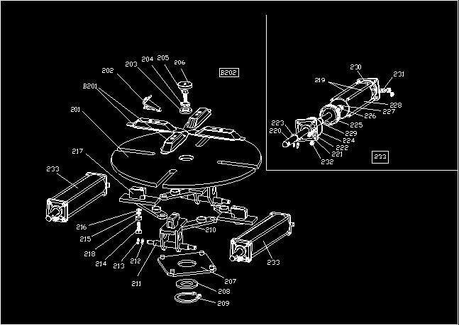
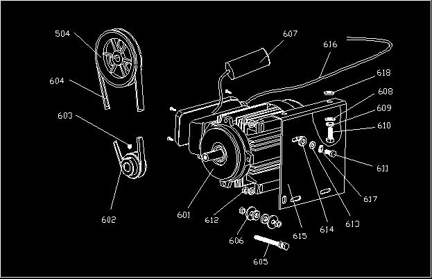
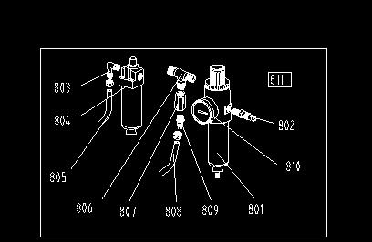
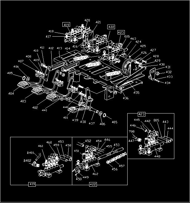
11 22. Rengaskoneen räjäytyskuvat ~ 11 ~
12 ~ 12 ~
13 ~ 13 ~
14 ~ 14 ~
15 ~ 15 ~
16 23. Varaosaluettelo THE SAME SPARE PART LIST OF COMMON&A VERSION ID Item No. Drawing No. Qty Product Name Parts of total assembly 1 U front cover 2 B GB/T 95 2 flat washer φ6*14*1.2 3 B GB/T 70 2 screw M6*55 4 B GB/T 70 2 screw M8*20 5 B GB/T 70 4 screw M5*16 6 B GB/T 95 4 flat washer φ5 7 C U rubber buffer B type 8 B GB/T 70 4 screw M6*40 9 Y U lifting lever 10 C U spring 11 C U rubber support 12 C U box 13 C rubber foot 14 B GB/T 70 4 screw M8*25 15 B GB/T 95 4 flat washer φ8*22*2 16 B GB/T 70 2 screw M10*25 17 B GB/T 41 2 nut M10 18 C U plastic cover 19 B GB/T 70 2 screw M8*25 20 GB/T flat washer φ12*30*3 21 GB/T Self-locking nut M12 Parts of column, horizontal arm& vertical arm 101 C U L-union 1/8-φ6 102 CZ U locking cylinder piston 103 C V-seal 60*50* B GB/T 95 4 flat washer φ6*14* B GB/T 70 4 screw M6* CX U locking cylinder cover φ CX U horizontal locking plate 108 B GB/T 95 2 flat washer φ8*17* C U horizontal locking spring 110 CX U arm protection support 111 B GB/T 95 1 flat washer φ8*17* B GB/T 95 2 flat washer φ8*17* B GB/T 70 2 screw M8* B GB/T 70 1 screw M8* U knob 116 U plastic cover 117 U spring 118 U vertical locking plate 119 C U spring 120 U hexagonal vertical arm 121 U buffer bush 122 CX U pulley 123 CX U mounting head ~ 16 ~
17 124 C U pin 125 B GB/T 78 1 screw M10* CX U flat washer 127 B GB/T 80 3 screw M12* U shock absorber 129 B GB/T screw M6* CZ U washer 131 'CZ U mounting head 132 B GB/T self-locking nut M8 133 B GB/T screw M6* B GB/T self-locking nut M B GB/T 95 2 flat washer φ12*25*2 136 CX U horizontal locking cone 137 B GB/T self-locking nut M8 138 C U T-union 1/8-2*φ6 139 C C hose 6*4 140 C C hose 6*4 141 C C union 1/8-φ6 142 CZ U complete switch handle 143 B GB/T 70 4 screw M6* C C hose 6*4 145 C JB O-seal φ68.26* C U tightener 147 C U cylinder rod 148 B GB/T self-locking nut M8 149 C U flange without handle 150 C JB/T V-seal φ20*36*8 151 C U tilting cylinder piston 152 B GB/T nut M12*7* C U tilting cylinder 154 C C union 1/8-φ6 155 C U flange with handle 156 CX U bell-mouthed sheath 157 C U rubber sheath 158 B GB/T screw M10* CX U flat washer 161 B GB/T self-locking nut M B GB/T 27 1 screw M10* CX U tilting pin 165 B GB/T screw M5* C U plastic cover 167 C U plastic cover 168 B GB/T 95 2 flat washer φ6*14* C U flat washer 170 C U cover 171 C plastic cover 172 CZ U complete tilting cylinder 173 U vertical column 174 U complete locking cylinder 175 C U switch 176 CX U valve pole 177 C U button ~ 17 ~
18 178 C U cover 179 C U spacer 180 C JB O-seal 7.5* B retainer ring φ8 182 U Tilting seat Parts of turning table assembly 201 CX U turntable 202 CX U jaw 203 CX U turntable washer 204 B GB/T 95 1 spring washer φ B GB/T screw M16* C U cap 207 CX U control plate 208 CX U washer 209 B GB/T retainer ring φ CX U connecting rod 211 CX U slide guide with pin 212 B GB/T 95 4 flat washer φ12*25*2 213 B GB/T retainer ring φ B GB/T 80 4 screw M12* B GB/T 95 4 spring washer φ B GB/T 95 4 flat washer φ12*30*3 217 CX U slide guide 218 CX U flat spacer for chuck 219 C U tightener 220 C U cylinder rod 221 C U flange without handle 222 C C union 1/8-φ8 223 C JB/T V-seal UHS-20*28* C JB O-seal 63* C U piston 226 B GB/T 95 2 flat washer φ12*25*2 227 B GB/T nut M12*7* C U clamping cylinder 229 C JB O-seal 20* C U flange with handle 231 C U L-union 1/8-φ8 232 B GB/T self-locking nut M8 233 CZ U complete clamping cylinder Parts of bead breaker cylinder& breaker arm assembly 301 B U screw M14* B GB/T self-locking nut M6 303 C C L-union 1/4-φ8 304 B GB/T nut M16* B GB/T 95 1 flat washer φ16*28*2 306 C JB O-seal 16* C JB O-seal 20* C JB O-seal 180*5 309 CX U bead breaker cylinder lid(front) 310 C U bead breaker rod 311 C JB/T V-seal 185*168*11.5 ~ 18 ~
19 312 C U piston 313 CX U bead breaker cylinder 314 B GB/T screw M6* CX U shovel 316 B GB/T 70 1 screw M12* B GB/T self-locking nut M C U guide belt 319 B GB/T 95 2 spring washer φ B GB/T retainer ring φ B GB/T 96 1 flat washer φ16*28*2 322 U bead breaker arm 323 CX U pin 324 CX U rotating pin 325 B GB/T 95 2 flat washer φ12*25*2 326 B GB/T self-locking nut M B GB/T flat washer φ8*30*3 328 B GB/T93 1 spring washer φ8 329 B GB/T screw M8* C C union 1/8-φ8 331 GB/T self-locking nut M U sheath 333 U pin 334 CZ U complete bead breaker cylinder Parts of pedals assembly 401 U pedal 402 U pedal 403 U pedal 404 U pedal 405 B GB/T retainer ring φ B GB/T95 2 flat washer φ12*25*2 407 B GB/T screw M4* B GB/T flat washer φ4 409 B GB/T95 3 self-locking nut M4 410 B GB/T self-locking nut M8 411 B GB/T flat washer φ8*17* C U cam connecting rod 413 C U pedal support 414 C U spring 415 C U cam 416 C U flat washer 417 B GB/T screw M6* B GB/T95 14 flat washer φ6*12*1 419 CZ complete 5-way valve 420 B GB/T tap screw ST2.9* CX U cam cover 422 CZ complete 5-way valve 423 CZ complete 5-way valve 424 C U switch cover 425 B GB/T 41 2 nut M4 426 C switch 427 B GB/T 70 1 screw M6* B GB/T 95 1 flat washer φ6*12*1 ~ 19 ~
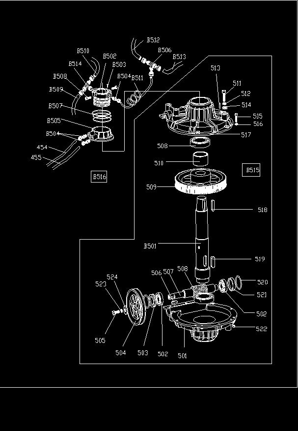
20 429 B GB/T 95 4 flat washer φ4 430 B GB/T 70 4 screw M4* C U switch handle 432 B GB/T 41 1 self-locking nut M6 433 B GB/T 95 1 flat washer φ4 434 B GB/T screw M4* CX U connecting rod 436 B GB/T 41 1 self-locking nut M8 437 CX U pedal shaft 438 B GB/T 41 2 nut M8 439 C U twist spring 440 B GB/T 70 1 screw M8* B GB/T 70 3 screw M8* C L-union 1/8-φ8 443 C hose 5*8 444 C hose 5*8 445 C T-union 1/8-2*φ8 446 C hose 5*8 447 C L-union 1/8-φ8 448 C U way valve 449 C U valve cover 450 B GB/T 70 6 tap screw ST2.9* C C silencer 1/8" 452 C hose 5*8 453 CX U valve pole 454 C hose 5*8 455 C hose 5*8 456 C U spacer 457 C JB O-seal 12*20*4 458 C hose 6*4 459 C hose 6*4 460 C L-union 1/8-φ6 461 C adjust valve 1/8-φ6 462 U way valve 463 CZ wire 3*1.5 Parts of transmission assembly 501 CZ U B 1 bottom cover 502 C GB/T bearing C GB/T seal φ20*35*8 504 CZ U pulley 505 B GB/T 70 1 screw M8* B GB/T key 6* CZ U worm screw 508 C GB/T bearing C U worm gear 510 CZ U spacer 511 B GB/T screw M10* B GB/T93 6 spring washer φ B GB/T pin 6* B GB/T95 6 flat washer φ10*20*2 515 B GB/T screw M6* B GB/T95 10 flat washer φ6*14*1.2 ~ 20 ~
21 517 CZ U A 1 upper cover 518 B GB/T key 10* B GB/T key 14* C JB O-seal φ27.8* C U seal 522 B GB/T self-locking nut M6 523 B GB/T93 1 Spring washer φ8 524 B GB/T95 2 Flat washerφ8*30*3 Parts of motor assembly 601 C motor MY CX U motor pulley 603 B GB/T 71 1 screw M8* C GB/T belt A B GB/T 71 1 screw M8* B GB/T 71 2 flat washer φ8.5*30*3 607 GB/T capacitor 608 B GB/T flat washer φ10*20*2 609 B GB/T93 2 spring washer φ B GB/T 70 2 screw M10* B GB/T 70 4 screw M8* B GB/T95 7 nut M8 613 B GB/T flat washer φ8*22* C U rubber washer 615 CX U motor support 616 CZ RVV 1 wire 5*1 617 B GB/T93 2 spring washer φ8 618 C U rubber washer Parts of air filter& oil fog maker assembly 801 C U relief pressure filter 802 C U quick nozzle 803 C U L-union 804 C oil fog maker 805 C U hose 5*8 806 C big T-joint 807 C union 1/4-1/4 808 C hose 5*8 809 C union 1/8-φ manometer 811 CZ oil fog maker assembly THE SPECIAL SPARE PART LIST OF COMMON VERSION B001 U body B002 U left cover B201 CX U slide B202 CZ U complete turntable Φ615 B401 C hose 5*8 B402 C L-union 1/8-φ6 B501 CZ U worm gear shaft B502 CZ U rotating union mandrel B503 B GB/T screw M4*6 B504 C C union 1/8"-φ8 B505 CZ U rotating valve casing ~ 21 ~
22 B506 C C T-union 3*φ8 B507 C JB O-seal 59.9*2.62 B508 B GB/T 70 2 screw M6*20 B509 C air inlet hose 5*8 B510 C air inlet hose 5*8 B511 C hose 5.5*φ8 B512 C air outlet hose 5*8 B513 C air outlet hose 5*8 B514 C C T-union 1/8-2*φ8 B515 CZ U complete gearbox B516 CZ U complete rotating union B701 Y U air gauge B702 Y U hose B703 C U nut B704 C union 1/4-1/4 B705 B GB/T flat washer φ13 B706 C AR pressure reducer B707 C L-union 1/4-φ8 B708 C U hose 5*8 B709 U complete inflating gun THE SPECIAL SPARE PART LIST OF A VERSION A001 U A 1 body A002 U A 1 left cover A201 CZ U A 1 complete turntable Φ615a A501 CZ U A 1 worm gear shaft A502 CZ U complete gear box A01 C /4-φ10 4 union 1/4-φ10 A02 C *φ10 4 hose 6.5*φ10 A03 C hose 5*8 A04 C *φ8 1 T-union A05 C hose 5*8 A06 C *φ8 1 hose 5.5*φ8 A07 C /8-φ8 1 union 1/8-φ8 A08 C U A 1 rotating valve casing A09 C hose 5*8 A10 C hose 5*8 A11 C *8 1 hose 12*8 A12 C *8 1 hose 12*8 A13 C hose 5*8 A14 B GB/T 70 4 screw M6*30 A15 C U A 1 exhaust valve A16 C U A 1 rubber sheet A17 B GB/T 70 2 screw M6*20 A18 C U A 1 exhaust valve cover A19 B GB/T95 6 nut M6 A20 C hose 5*8 A21 C /4-φ8 1 L-union 1/4-φ8 A22 CX U A 1 exhaust valve support A23 B GB/T95 2 nut M6 A24 B GB/T 70 2 screw M6*16 A25 C /8-2*φ8 1 T-union 1/8-2*φ8 A26 C U A 1 rubber washer φ24*34*2 A27 U A 1 tie-in A28 B GB/T95 2 self-locking nut M10 A29 C U A 1 rubber casing ~ 22 ~
23 A30 C U A 1 hose A31 U A 1 tie-in A32 C water discharge valve A33 B GB/T 70 2 screw M10*25 A34 CX U A 1 tank A35 C GB-TQ-L10 1 safety valve A36 Y connection hose A37 C X8 1 hose 5*8 A38 C X8 1 hose 5*8 A39 CZ complete pressure gauge box A40 C /2-φ12 4 union 1/2-φ12 A41 C /8-φ8 2 union 1/8-φ8 A42 C *2 1 O-seal A43 C *2.8 3 O-seal φ62*2.8 A44 B GB/T 70 2 screw M6*25 A45 C X8 1 hose 5*8 A46 C /8-2*φ8 1 T-union 1/8-2*φ8 A47 C X8 1 hose 5*8 A48 CX slide plate A49 B GB/T 70 2 screw M4*6 A50 C U A 1 rotating union mandrel A51 C union 3/8-φ10 A52 C A 1 pressure gauge box A53 CX A 1 button A54 C A 1 spring A55 CX A 1 valve A56 C /8 1 plug A57 C *1.8 1 O-seal 4*1.8 A58 C *1.8 1 O-seal 6.9*1.8 A59 CX A 1 shaft A60 P pressure gauge A61 CZ A 1 seat with holes A62 C union 1/8-φ8 A63 B GB/T 70 7 screw M4*30 A64 CX A 1 pressure gauge box support A65 B GB/T 70 2 screw M6*16 A66 B GB/T flat washer φ8*30*3 A67 B GB/T93 2 spring washer φ8 A68 B GB/T 70 2 screw M6*25 A69 CX U A 1 inflation pedal support A70 C plug 1/8 A71 C L-union 1/8-φ8 A72 C L-union 1/8-φ8 A73 B GB/T 70 1 screw M5*20 A74 B GB/T 41 1 self-locking nut M5 A75 CX U A 1 valve connecting rod A76 B GB/T 70 1 screw M6*25 A77 B GB/T95 1 flat washer φ6*12*1 A78 B GB/T 70 1 screw M8*25 A79 B GB/T 41 1 Nut 8 A80 B GB/T 41 1 self-locking nut M10 A81 C U A 1 spring A82 B GB/T 70 1 screw M10 A83 C *40 1 pin A84 C U A 1 rubber cover ~ 23 ~
24 A85 CX U A 1 pedal connecting rod A86 B GB/T 41 1 nut M6 A87 C U spring A88 B GB/T 70 1 screw M6*25 A89 B GB/T 41 2 nut A90 B GB/T 41 4 self-locking nut M6 A91 B GB/T95 4 flat washer φ6*12*1 A92 B GB/T 70 4 screw M6*20 A93 U way valve A94 C JB O-seal 12*20*4 A95 C U valve cover A96 B GB/T 70 2 tap screw ST2.9*16 A97 C U valve spacer A98 CX U A 1 valve pole A99 C JB O-seal 12*20*4 A100 CZ complete inflation pedal A101 U A 4 Locking sliders A102 U A 1 Complete rotating valve casing A103 C hose 5*8 ~ 24 ~
25 ~ 25 ~
26 Index 1. Introduction Safety requlations Warning labels Technical data Transportation Unpacking Workspace requirements Product diagram Installation Pneumatic connection Electrical connection Machine controls Preparations Breaking the bead Clamping the wheel Demounting the tire Mounting the tire Inflating the tire Transportation and storage Maintenance Troubleshooting Explosion pictures Spare parts list ~ 26 ~

27 Tire changer Read this manual carefully before using the machine. Keep this manual safe for future use. 1. Introduction The semi-automatic tire changer is designed for mounting and demounting tires. Please use the machine only for its indented purpose, not for any other purposes. The manufacturer shall not be responsible for any damage or injury caused by failure to comply with these regulations. 2. Safety regulations This machine is to be used only by those trained or qualified to do it, or someone who has read the manual carefully or has experience with operating similar machinery. Any changes to the machine that haven t been permitted by the manufacturer may cause the machine to malfunction or be damaged, in which case the manufacturer can cancel the warranty. The warranty expires in one year. 3. Warning labels 01 Don t place your hands under the mount/demount head during operation 02 Don t place your hands between the jaws during operation 03 Don t place your hands on the tire bead while demounting it 04 Make sure to check whether the system is properly grounded 05 Don t put your feet between the bead breaker shovel and the body during operation 06 Safety instructions 07 Be careful with the pneumatic compressor ~ 27 ~
28 4. Technical data External locking rim dimensions Internal locking rim dimensions Max. wheel diameter Max. wheel width Bead breaker force at 1 Mpa Working Pressure Power supply Motor power Max. rotating torque (Turntable) Overall dimensions Noise level 12~23" 14~26" 1043mm(45") 406mm(16") 2500kg 8-10bar 380V 0.37 kw 1078 Nm 113*90*103 cm <75dB 5. Transportation Move the tire changer with a forklift by lifting from the base of the machine (Fig 1). 6. Unpacking Pull out the nails that hold the package on the plate with pliers and unpack the carton and plastic cover. After unpacking, check if there are any parts that are clearly damaged. Fig 1 7. Workspace requirements Follow the safety regulations when choosing the workspace. Connect the machine to electricity and air source following the manual s instructions. The workspace must have good air conditioning. For the machine to be operated correctly, the workspace must have enough clear space from each wall as shown in Fig 2. The machine must be protected from rain and sunshine. Fig 2 ~ 28 ~

29 8. Product diagram Tire changer ST-1231 A Locking switch I Bead breaker pedal B Vertical arm J Turntable pedal C Mount/demount head K Tire iron D Jaw L Rubber cover E Turntable M Bead breaker G Tilting pedal O Column H Jaw pedal P Horizontal arm ~ 29 ~
 Insert screw (13) into the hole on the column and add tilting cylinder plug (7), tighten with self-locking nuts (12).")
 Attach the plastic cover (5) with two bolts (4) 5) Attach the smaller plastic cover (3) on the column with a screw (2). 10.")
30 9. Installation 1) Place the tilting hinge (1 in Fig 3) on the body (9) with four bolts and push the air hose (6) through the hole on the column. Tighten with 4 self-locking nuts. 2) Insert screw (13) into the hole on the column and add tilting cylinder plug (7), tighten with self-locking nuts (12). 3) Unscrew the two bolts (11) on the left cover (10) and remove the cover, connect the air hose (8) to the side holes which control the tilting 5-way valve. Put the left cover back on the machine. 4) Attach the plastic cover (5) with two bolts (4) 5) Attach the smaller plastic cover (3) on the column with a screw (2). 10. Pneumatic connection 1) Push down the pedal to make sure that the turntable jaws don t open unexpectedly. 2) Attach the tire machine to pneumatic air source with an air hose (inner diameter 7-8 mm). The air pressure must be 8-10 bar 3) Air pressure must not exceed 10 bar. Attach the tire changer Fig 3 to pneumatic air source with a coupling found at the back of the machine. 11. Electrical connection Warning: Make sure that the voltage source matches with the machine s technical data. Attach the electrical connection to a grounded socket. Make sure that it provides at least 30 A of power. 12. Machine controls The locking switch (A) can be used to lock the vertical arm (B) and horizontal arm (P). The mount/demount head (C) can be automatically lifted for 2-3 mm while it s locked. The tilting pedal (G) can be used to tilt the column (O). Fig 4 The jaw pedal (H) opens and closes the jaws (D) on the turntable. The bead breaker pedal (I) controls the bead breaker (M). The turntable pedal (J) is used for rotating the turntable (E) clockwise or counterclockwise. The tire machine can be used in three different ways: 1) Breaking the tire bead 2) Demounting a tire 3) Mounting a tire Warning: Do not wear loose clothing when using the machine. Please use protective glasses and gloves and wear non-slip shoes. Before using the machine, make sure that the tire is completely empty and that any wheel weights have been removed from the rim. ~ 30 ~ Fig
 Press the bead breaker pedal to close the bead breaker. 3) Press down the jaw pedal to open the jaws completely. By pressing the pedal again the jaws are released.")
31 13. Preparations Make sure that the tire machine works correctly after installing it. 1) Press the turntable pedal down. The turntable should rotate clockwise. 2) Press the bead breaker pedal to close the bead breaker. 3) Press down the jaw pedal to open the jaws completely. By pressing the pedal again the jaws are released. If the pressing is continued, the jaws close. 4) Press the tilting pedal. The column tilts back to its original position. By pressing again, the column returns to its working position. 5) Press the locking switch to make the vertical arm and the horizontal arm lock in place. This also causes the mount/demount head to rise automatically to a distance of 2-3 mm from the rim s edge. By pressing the switch again both arms become mobile. 14. Breaking the bead Make sure to completely remove any air in the tire. Place the tire against the rubber padding. Bring the bead breaker against the tire bead at a distance of about 10 mm from the edge of the rim (Fig 6). Press the bead breaker pedal to push the breaker into the tire. Repeat the above procedures on different positions around the tire and on both sides of the tire until the bead has been completely released from the rim. 15. Clamping the wheel Warning: Make sure to remove all wheel weights from the rim and to completely empty the tire before demounting it. Fig 6 Apply lubricating grease (or a similar lubricant) around the tire bead. If the lubricant isn t used, the tire may be badly damaged or it may even tear. Press the tilting pedal to tilt the column to its original position. Clamp the rim either from the outside or from the inside. Do not place your hands under the wheel while clamping it. Place the when in the middle of the turntable. Make sure that the wheel is held in place with all four jaws. The wheel must be clamped according to its dimensions: a) Clamping the rim from the outside (wheel diameter ): Lift the jaw pedal halfway down to its middle position, positioning the jaws on the turntable according to the rim s size. Put the wheel on the turntable, hold the rim and lift the pedal of the jaws until the wheel is secured in place by the jaws. b) Clamping the rim from the inside (wheel diameter ) Position the jaws on the middle of the turntable in their closed position. Put the tire on the turntable and lift the jaw pedal to open the jaws position and this way clamping onto the rim from the inside. Warning: Before continuing, make sure that the wheel is firmly kept in place. ~ 31 ~

32 16. Demounting the tire 1) Lower the horizontal arm to its working position. 2) Lower the vertical arm until the mount/demount head rests next to the edge of the rim. Flip the pneumatic locking button to lock the vertical and horizontal arms in position. Make sure that there is a distance of about 2-3 mm between the rim s edge and the mount/demount head. 3) Insert the tire iron between the tire bead and the mount/demount head s front section, and lift the tire above the mount/demount head as shown in Fig 7. 4) With the mount/demount head held in position, press the turntable pedal to rotate the turntable clockwise until the Fig 7 tire is completely separated from the rim. Lift the tire and demount the other bead by following these steps again. Attention: The tire can easily slip off the mount/demount head. To prevent this, first rotate the turntable 1-2 cm counterclockwise before rotating it clockwise. 17. Mounting the tire Make sure that the tire and the rim are of same size. Also check the tire for any damages. To avoid damaging the tire bead, the tire bead and rim edge must be lubricated. Clamp the wheel with the jaws. Place the tire against the rim and move the mount/demount head above it. Place one side of the tire bead above the rear section of the mount/demount head and the other side below the mount/demount head s front section. Press the tire with hands or assist arm and spin Fig 8 the turntable to mount the tire s lower bead. Repeat the above procedure to mount the tire s upper bead (Fig 8). 18. Inflating the tire Inflate the tire carefully and always follow the instructions. If the tire bursts, it can cause serious injuries. The tire changer is equipped with a pressure relief valve, which keeps the pressure from rising above 3.5 bar. Tire may, however, burst because of the following reasons: 1) The tire and the rim are not of the same size 2) The tire or the rim is damaged 3) The pressure of tire inflation is over the maximum pressure recommended by the manufacturer 4) The operator has failed to comply with safety regulations Please do this: 1) Remove the valve cap from the valve stem. 2) Make sure that the air nozzle is pressed down completely over the threads of the valve stem. 3) Make sure that the rim and the tire are of the same size. Fig 9 ~ 32 ~


33 4) Lubricate both the tire bead and the wheel rim, add lubrication if needed. 5) Inflate the tire gradually. When inflating, check the pressure listed on the pressure gauge, and also keep an eye out for whether the bead is fixed on the rim or not. Repeat until the bead is tightly secured to the rim. 6) Continue inflating and checking the air pressure regularly until the pressure has reached the tire s recommended pressure. The best results can be achieved by at first safely going bit over the pressure recommended by the manufacturer, and only after doing this lowering the pressure to the level recommended by the manufacturer. By inflating the tire this way, it settles on the rim better and the balance of the tire becomes more precise. Warning: Never exceed the maximum pressure stated by the tire manufacturer 19. Transportation and storage Disconnect the tire changer from electricity network and pneumatic supply. Move the tire changer with a forklift to its desired location and install it there. Fig 10 If the machine is being stored for extended periods of time, it must be disconnected from electricity and pneumatic air source. Lubricate any parts that need it. Empty the oil and water tanks. Protect the machine from dust. 20. Maintenance Performing maintenance is reserved to professionals. To prolong the machine s life, maintain the machine on a regular basis according to the manual. Otherwise Fig 11 the machine s reliability will be impacted. Caution: Before performing any maintenance, the tire changer must be disconnected from electricity network and pneumatic air supply. The jaw pedal and turntable pedal must be pressed 3-4 times to exhaust any compressed air that was left in the machine. Clean the machine once every day after using it. Clean the turntable with diesel oil once per week and lubricate the jaws and their slides. Empty any water from the air filter daily to ensure that the cylinder works perfectly (Fig 10). Note: After the first 20 days of use, tighten the jaws with the screws on the Fig 12 turntable (Fig 11). If the tire changer no longer works correctly, check if the machine s belt is tight. Detach the machine s side panel by unscrewing the screws. Fasten the belt by adjusting the screws (Fig 11) If the vertical arm no longer locks in place, adjust it like in Fig 12. To make sure that the jaws and the bead breaker work correctly, clean their valves (Fig 13): 1) Remove the cover on the left side of the machine by unscrewing two screws. 2) Loosen the valve mufflers (A) of the jaw pedal and bead breaker pedal. Fig 13 ~ 33 ~
34 3) Clean the mufflers with compressed air. If they are damaged, please replace them with spare parts mentioned in the spare parts list. 21. Troubleshooting Problem Cause Solution The turntable only rotates in one Reverse switch broken Replace the reverse switch direction or doesn t rotate Damaged belt Replace the belt When demounting or mounting the wheel, the turntable doesn t lock in place and spins with the wheel; The jaws open and close slowly; The turntable locks the rim incorrectly The motor has malfuntioned Check the motor cable and terminal block s wires; Replace the motor if it is broken Pneumatic air leakage Check all the parts of the air network Jaw cylinder doesn t work Replace the cylinder piston Jaws are worn down Broken seals of the chuck cylinder Replace the jaws Replace them The mount/demount head always makes contact with the rim during operation The bead breaker pedal and jaw pedal don t return to their original positions The bead breaker is difficult to operate The locking plate is incorrectly adjusted or unqualified The screws on the cylinder are loose; The vertical arm can t be locked by the locking plate Pedal spring is broken Clogged silencer The piston has detached or he seals of the bead breaker cylinder are broken or the pneumatic lubrication has been distrupted Replace it or adjust it Tighten the screws; Replace the locking plate Replace it Clean it or replace it Check the connections, seals and lubrication ~ 34 ~

35 22. Explosion pictures ~ 35 ~
36 ~ 36 ~
37 ~ 37 ~
38 ~ 38 ~
39 ~ 39 ~
40 23. Spare parts list THE SAME SPARE PART LIST OF COMMON&A VERSION ID Item No. Drawing No. Qty Product Name Parts of total assembly 1 U front cover 2 B GB/T 95 2 flat washer φ6*14*1.2 3 B GB/T 70 2 screw M6*55 4 B GB/T 70 2 screw M8*20 5 B GB/T 70 4 screw M5*16 6 B GB/T 95 4 flat washer φ5 7 C U rubber buffer B type 8 B GB/T 70 4 screw M6*40 9 Y U lifting lever 10 C U spring 11 C U rubber support 12 C U box 13 C rubber foot 14 B GB/T 70 4 screw M8*25 15 B GB/T 95 4 flat washer φ8*22*2 16 B GB/T 70 2 screw M10*25 17 B GB/T 41 2 nut M10 18 C U plastic cover 19 B GB/T 70 2 screw M8*25 20 GB/T flat washer φ12*30*3 21 GB/T Self-locking nut M12 Parts of column, horizontal arm& vertical arm 101 C U L-union 1/8-φ6 102 CZ U locking cylinder piston 103 C V-seal 60*50* B GB/T 95 4 flat washer φ6*14*1.2 ~ 40 ~
41 105 B GB/T 70 4 screw M6* CX U locking cylinder cover φ CX U horizontal locking plate 108 B GB/T 95 2 flat washer φ8*17* C U horizontal locking spring 110 CX U arm protection support 111 B GB/T 95 1 flat washer φ8*17* B GB/T 95 2 flat washer φ8*17* B GB/T 70 2 screw M8* B GB/T 70 1 screw M8* U knob 116 U plastic cover 117 U spring 118 U vertical locking plate 119 C U spring 120 U hexagonal vertical arm 121 U buffer bush 122 CX U pulley 123 CX U mounting head 124 C U pin 125 B GB/T 78 1 screw M10* CX U flat washer 127 B GB/T 80 3 screw M12* U shock absorber 129 B GB/T screw M6* CZ U washer 131 'CZ U mounting head 132 B GB/T self-locking nut M8 133 B GB/T screw M6* B GB/T self-locking nut M B GB/T 95 2 flat washer φ12*25*2 136 CX U horizontal locking cone 137 B GB/T self-locking nut M8 ~ 41 ~
42 138 C U T-union 1/8-2*φ6 139 C C hose 6*4 140 C C hose 6*4 141 C C union 1/8-φ6 142 CZ U complete switch handle 143 B GB/T 70 4 screw M6* C C hose 6*4 145 C JB O-seal φ68.26* C U tightener 147 C U cylinder rod 148 B GB/T self-locking nut M8 149 C U flange without handle 150 C JB/T V-seal φ20*36*8 151 C U tilting cylinder piston 152 B GB/T nut M12*7* C U tilting cylinder 154 C C union 1/8-φ6 155 C U flange with handle 156 CX U bell-mouthed sheath 157 C U rubber sheath 158 B GB/T screw M10* CX U flat washer 161 B GB/T self-locking nut M B GB/T 27 1 screw M10* CX U tilting pin 165 B GB/T screw M5* C U plastic cover 167 C U plastic cover 168 B GB/T 95 2 flat washer φ6*14* C U flat washer 170 C U cover 171 C plastic cover 172 CZ U complete tilting cylinder ~ 42 ~
43 173 U vertical column 174 U complete locking cylinder 175 C U switch 176 CX U valve pole 177 C U button 178 C U cover 179 C U spacer 180 C JB O-seal 7.5* B retainer ring φ8 182 U Tilting seat Parts of turning table assembly 201 CX U turntable 202 CX U jaw 203 CX U turntable washer 204 B GB/T 95 1 spring washer φ B GB/T screw M16* C U cap 207 CX U control plate 208 CX U washer 209 B GB/T retainer ring φ CX U connecting rod 211 CX U slide guide with pin 212 B GB/T 95 4 flat washer φ12*25*2 213 B GB/T retainer ring φ B GB/T 80 4 screw M12* B GB/T 95 4 spring washer φ B GB/T 95 4 flat washer φ12*30*3 217 CX U slide guide 218 CX U flat spacer for chuck 219 C U tightener 220 C U cylinder rod 221 C U flange without handle 222 C C union 1/8-φ8 ~ 43 ~
44 223 C JB/T V-seal UHS-20*28* C JB O-seal 63* C U piston 226 B GB/T 95 2 flat washer φ12*25*2 227 B GB/T nut M12*7* C U clamping cylinder 229 C JB O-seal 20* C U flange with handle 231 C U L-union 1/8-φ8 232 B GB/T self-locking nut M8 233 CZ U complete clamping cylinder Parts of bead breaker cylinder& breaker arm assembly 301 B U screw M14* B GB/T self-locking nut M6 303 C C L-union 1/4-φ8 304 B GB/T nut M16* B GB/T 95 1 flat washer φ16*28*2 306 C JB O-seal 16* C JB O-seal 20* C JB O-seal 180*5 309 CX U bead breaker cylinder lid(front) 310 C U bead breaker rod 311 C JB/T V-seal 185*168* C U piston 313 CX U bead breaker cylinder 314 B GB/T screw M6* CX U shovel 316 B GB/T 70 1 screw M12* B GB/T self-locking nut M C U guide belt 319 B GB/T 95 2 spring washer φ B GB/T retainer ring φ B GB/T 96 1 flat washer φ16*28*2 ~ 44 ~
45 322 U bead breaker arm 323 CX U pin 324 CX U rotating pin 325 B GB/T 95 2 flat washer φ12*25*2 326 B GB/T self-locking nut M B GB/T flat washer φ8*30*3 328 B GB/T93 1 spring washer φ8 329 B GB/T screw M8* C C union 1/8-φ8 331 GB/T self-locking nut M U sheath 333 U pin 334 CZ U complete bead breaker cylinder Parts of pedals assembly 401 U pedal 402 U pedal 403 U pedal 404 U pedal 405 B GB/T retainer ring φ B GB/T95 2 flat washer φ12*25*2 407 B GB/T screw M4* B GB/T flat washer φ4 409 B GB/T95 3 self-locking nut M4 410 B GB/T self-locking nut M8 411 B GB/T flat washer φ8*17* C U cam connecting rod 413 C U pedal support 414 C U spring 415 C U cam 416 C U flat washer 417 B GB/T screw M6* B GB/T95 14 flat washer φ6*12*1 419 CZ complete 5-way valve ~ 45 ~
46 420 B GB/T tap screw ST2.9* CX U cam cover 422 CZ complete 5-way valve 423 CZ complete 5-way valve 424 C U switch cover 425 B GB/T 41 2 nut M4 426 C switch 427 B GB/T 70 1 screw M6* B GB/T 95 1 flat washer φ6*12*1 429 B GB/T 95 4 flat washer φ4 430 B GB/T 70 4 screw M4* C U switch handle 432 B GB/T 41 1 self-locking nut M6 433 B GB/T 95 1 flat washer φ4 434 B GB/T screw M4* CX U connecting rod 436 B GB/T 41 1 self-locking nut M8 437 CX U pedal shaft 438 B GB/T 41 2 nut M8 439 C U twist spring 440 B GB/T 70 1 screw M8* B GB/T 70 3 screw M8* C L-union 1/8-φ8 443 C hose 5*8 444 C hose 5*8 445 C T-union 1/8-2*φ8 446 C hose 5*8 447 C L-union 1/8-φ8 448 C U way valve 449 C U valve cover 450 B GB/T 70 6 tap screw ST2.9* C C silencer 1/8" 452 C hose 5*8 ~ 46 ~
47 453 CX U valve pole 454 C hose 5*8 455 C hose 5*8 456 C U spacer 457 C JB O-seal 12*20*4 458 C hose 6*4 459 C hose 6*4 460 C L-union 1/8-φ6 461 C adjust valve 1/8-φ6 462 U way valve 463 CZ wire 3*1.5 Parts of transmission assembly 501 CZ U B 1 bottom cover 502 C GB/T bearing C GB/T seal φ20*35*8 504 CZ U pulley 505 B GB/T 70 1 screw M8* B GB/T key 6* CZ U worm screw 508 C GB/T bearing C U worm gear 510 CZ U spacer 511 B GB/T screw M10* B GB/T93 6 spring washer φ B GB/T pin 6* B GB/T95 6 flat washer φ10*20*2 515 B GB/T screw M6* B GB/T95 10 flat washer φ6*14* CZ U A 1 upper cover 518 B GB/T key 10* B GB/T key 14* C JB O-seal φ27.8* C U seal ~ 47 ~
48 522 B GB/T self-locking nut M6 523 B GB/T93 1 Spring washer φ8 524 B GB/T95 2 Flat washerφ8*30*3 Parts of motor assembly 601 C motor MY CX U motor pulley 603 B GB/T 71 1 screw M8* C GB/T belt A B GB/T 71 1 screw M8* B GB/T 71 2 flat washer φ8.5*30*3 607 GB/T capacitor 608 B GB/T flat washer φ10*20*2 609 B GB/T93 2 spring washer φ B GB/T 70 2 screw M10* B GB/T 70 4 screw M8* B GB/T95 7 nut M8 613 B GB/T flat washer φ8*22* C U rubber washer 615 CX U motor support 616 CZ RVV 1 wire 5*1 617 B GB/T93 2 spring washer φ8 618 C U rubber washer Parts of air filter& oil fog maker assembly 801 C U relief pressure filter 802 C U quick nozzle 803 C U L-union 804 C oil fog maker 805 C U hose 5*8 806 C big T-joint 807 C union 1/4-1/4 808 C hose 5*8 809 C union 1/8-φ manometer ~ 48 ~
49 811 CZ oil fog maker assembly THE SPECIAL SPARE PART LIST OF COMMON VERSION B001 U body B002 U left cover B201 CX U slide B202 CZ U complete turntable Φ615 B401 C hose 5*8 B402 C L-union 1/8-φ6 B501 CZ U worm gear shaft B502 CZ U rotating union mandrel B503 B GB/T screw M4*6 B504 C C union 1/8"-φ8 B505 CZ U rotating valve casing B506 C C T-union 3*φ8 B507 C JB O-seal 59.9*2.62 B508 B GB/T 70 2 screw M6*20 B509 C air inlet hose 5*8 B510 C air inlet hose 5*8 B511 C hose 5.5*φ8 B512 C air outlet hose 5*8 B513 C air outlet hose 5*8 B514 C C T-union 1/8-2*φ8 B515 CZ U complete gearbox B516 CZ U complete rotating union B701 Y U air gauge B702 Y U hose B703 C U nut B704 C union 1/4-1/4 B705 B GB/T flat washer φ13 B706 C AR pressure reducer B707 C L-union 1/4-φ8 B708 C U hose 5*8 B709 U complete inflating gun ~ 49 ~
50 THE SPECIAL SPARE PART LIST OF A VERSION A001 U A 1 body A002 U A 1 left cover A201 CZ U A 1 complete turntable Φ615a A501 CZ U A 1 worm gear shaft A502 CZ U complete gear box A01 C /4-φ10 4 union 1/4-φ10 A02 C *φ10 4 hose 6.5*φ10 A03 C hose 5*8 A04 C *φ8 1 T-union A05 C hose 5*8 A06 C *φ8 1 hose 5.5*φ8 A07 C /8-φ8 1 union 1/8-φ8 A08 C U A 1 rotating valve casing A09 C hose 5*8 A10 C hose 5*8 A11 C *8 1 hose 12*8 A12 C *8 1 hose 12*8 A13 C hose 5*8 A14 B GB/T 70 4 screw M6*30 A15 C U A 1 exhaust valve A16 C U A 1 rubber sheet A17 B GB/T 70 2 screw M6*20 A18 C U A 1 exhaust valve cover A19 B GB/T95 6 nut M6 A20 C hose 5*8 A21 C /4-φ8 1 L-union 1/4-φ8 A22 CX U A 1 exhaust valve support A23 B GB/T95 2 nut M6 A24 B GB/T 70 2 screw M6*16 A25 C /8-2*φ8 1 T-union 1/8-2*φ8 A26 C U A 1 rubber washer φ24*34*2 A27 U A 1 tie-in ~ 50 ~
51 A28 B GB/T95 2 self-locking nut M10 A29 C U A 1 rubber casing A30 C U A 1 hose A31 U A 1 tie-in A32 C water discharge valve A33 B GB/T 70 2 screw M10*25 A34 CX U A 1 tank A35 C GB-TQ-L10 1 safety valve A36 Y connection hose A37 C X8 1 hose 5*8 A38 C X8 1 hose 5*8 A39 CZ complete pressure gauge box A40 C /2-φ12 4 union 1/2-φ12 A41 C /8-φ8 2 union 1/8-φ8 A42 C *2 1 O-seal A43 C *2.8 3 O-seal φ62*2.8 A44 B GB/T 70 2 screw M6*25 A45 C X8 1 hose 5*8 A46 C /8-2*φ8 1 T-union 1/8-2*φ8 A47 C X8 1 hose 5*8 A48 CX slide plate A49 B GB/T 70 2 screw M4*6 A50 C U A 1 rotating union mandrel A51 C union 3/8-φ10 A52 C A 1 pressure gauge box A53 CX A 1 button A54 C A 1 spring A55 CX A 1 valve A56 C /8 1 plug A57 C *1.8 1 O-seal 4*1.8 A58 C *1.8 1 O-seal 6.9*1.8 A59 CX A 1 shaft A60 P pressure gauge ~ 51 ~
52 A61 CZ A 1 seat with holes A62 C union 1/8-φ8 A63 B GB/T 70 7 screw M4*30 A64 CX A 1 pressure gauge box support A65 B GB/T 70 2 screw M6*16 A66 B GB/T flat washer φ8*30*3 A67 B GB/T93 2 spring washer φ8 A68 B GB/T 70 2 screw M6*25 A69 CX U A 1 inflation pedal support A70 C plug 1/8 A71 C L-union 1/8-φ8 A72 C L-union 1/8-φ8 A73 B GB/T 70 1 screw M5*20 A74 B GB/T 41 1 self-locking nut M5 A75 CX U A 1 valve connecting rod A76 B GB/T 70 1 screw M6*25 A77 B GB/T95 1 flat washer φ6*12*1 A78 B GB/T 70 1 screw M8*25 A79 B GB/T 41 1 Nut 8 A80 B GB/T 41 1 self-locking nut M10 A81 C U A 1 spring A82 B GB/T 70 1 screw M10 A83 C *40 1 pin A84 C U A 1 rubber cover A85 CX U A 1 pedal connecting rod A86 B GB/T 41 1 nut M6 A87 C U spring A88 B GB/T 70 1 screw M6*25 A89 B GB/T 41 2 nut A90 B GB/T 41 4 self-locking nut M6 A91 B GB/T95 4 flat washer φ6*12*1 A92 B GB/T 70 4 screw M6*20 A93 U way valve ~ 52 ~
53 A94 C JB O-seal 12*20*4 A95 C U valve cover A96 B GB/T 70 2 tap screw ST2.9*16 A97 C U valve spacer A98 CX U A 1 valve pole A99 C JB O-seal 12*20*4 A100 CZ complete inflation pedal A101 U A 4 Locking sliders A102 U A 1 Complete rotating valve casing A103 C hose 5*8 ~ 53 ~
54 ~ 54 ~

55 EY-VAATIMUSTENMUKAISUUSVAKUUTUS EG-FÖRSÄKRAN OM ÖVERENSSTÄMMELSE SAMSVARSERKLÆRING EC-DECLARATION OF CONFORMITY tyrelia.com HITSAAJANTIE 1 FI KOUVOLA FINLAND VAKUUTAMME, ETTÄ RENGASKONEEN ST-1231 VALMISTUS JA RAKENNE OVAT EUROOPAN YHTEISÖN KONEDIREKTIIVIN 2006/42/EY SÄÄNNÖSTEN MUKAISET JA NOSTIN ON STANDARDIEN EN : 2006+A1: 2009 MUKAINEN. RENGASKONE ST-1231 ON CCQS-UK Ltd. Suite B, Regal Court 112 London Road, Headington, Oxford, OX3 9AW, UK, CE-MERKINNÄN HYVÄKSYMISNUMERO 1105, TYYPPITARKASTAMA. SERTIFIKAATIN NUMERO: CE-C A. VI GARANTERE ATT KONSTRUKTION OCH TILLVERKNING AV DÄCKMASKIN ST ÖVERENSSTÄMMER MED EUROPEISKA GEMENSKAPENS MASKINDIREKTIV 2006/42/EG OCH STANDARDER EN : 2006+A1: DÄCKMASKIN ST-1231 HAR TYPBESIKTATS AV CCQS-UK Ltd. Suite B, Regal Court 112 London Road, Headington, Oxford, OX3 9AW, UK, CE-MÄRKNINGES GODKÄNNINGSNUMMER CERTIFIKATNR: CE-C A. BEKREFTER AT DÄECKMASKIN ST-1231 PRODUKSJON OG KONSTRUKSJON ER I SAMSVAR MED EUROPÆISKE FÆLLESSKAB MASKINDIREKTIV 2006/42/EF OG SAMSVAR MED STANDARDER EN : 2006+A1: DÄECKMASKIN ST-1231 ER TYPE INSPEKTION PÅ CCQS-UK Ltd. Suite B, Regal Court 112 London Road, Headington, Oxford, OX3 9AW, UK, CE MARK GODKENDELSNUMMER 1105, CERTIFIKAT NUMMER: CE-C A. DECLARES THAT TIRE CHANGER ST-1231 MANUFACTURING AND DESIGN COMPLIES EUROPEAN PARLIAMENT AND COUNSILS DIRECTIVE 2006/42/EC AND COMPLIES TO STANDARDS EN : 2006+A1: TIRE CHANGER ST-1231 IS TYPE EXAMINATED BY CCQS-UK Ltd. Suite B, Regal Court 112 London Road, Headington, Oxford, OX3 9AW, UK, CE MARKING NUMBER Certificate NO: CE-C- CE-C A. ~ 55 ~
RENGASKONE PL-1231 KÄYTTÖOHJE
 RENGASKONE PL-1231 KÄYTTÖOHJE SISÄLLYS 1. Esittely... 2 2. Turvallisuusohjeet... 2 3. Varoitustarrat... 2 4. Tekniset tiedot... 3 5. Kuljetus... 3 6. Pakkauksen purkaminen... 3 7. Työskentelyalueen vaatimukset...
RENGASKONE ST-1200 / ST-1203 KÄYTTÖOHJE
 RENGASKONE ST-00 / ST-03 KÄYTTÖOHJE SISÄLLYS. Esittely.... Turvallisuusohjeet... 3. Varoitustarrat.... Tekniset tiedot...3 5. Kuljetus...3 6. Pakkauksen purkaminen...3 7. Työskentelyalueen vaatimukset...3
RENGASKONE TIRE CHANGER ST-1236IT
 RENGASKONE TIRE CHANGER ST-1236IT KÄYTTÖOHJE USER S MANUAL Lue tämä käyttöohje huolellisesti kokonaisuudessaan ennen koneen asennusta ja käyttöä. Read the entire manual carefully and completely before
TIRE CHANGER RENGASKONE ST-1256 KÄYTTÖOHJE USER S MANUAL
 TIRE CHANGER RENGASKONE ST-1256 KÄYTTÖOHJE USER S MANUAL ~ 1 ~ Lue tämä käyttöohje huolellisesti kokonaisuudessaan ennen koneen asennusta ja käyttöä. Read the entire manual carefully and completely before
PAINEILMALETKUKELA-AUTOMAATTI AUTOMATIC AIR HOSE REEL
 MAV4 MAV5 MAV6 PAINEILMALETKUKELA-AUTOMAATTI AUTOMATIC AIR HOSE REEL Käyttöohje Instruction manual HUOMIO! Lue käyttöohjeet huolellisesti ennen laitteen käyttöä ja noudata kaikkia annettuja ohjeita. Säilytä
PARTS LIST Item Description Q'TY Item Description Q'TY
 PARTS LIST Item Description Q'TY Item Description Q'TY 1 Lower door 1 40 Jockey wheel axel 1 2 Safety switch 1 41 Power cord 1 3 Screw M4 35 4 42 Switch 1 4 Hex bolt M6 8 4 43 Lower shaft bracket 1 5 Washer
SAGA 150. Asennusohjeet. Mittaa oven korkeus. Piirrä seinään oven kiinni -päätyyn seinäkannattimen kohdalle vaakaviiva korkeudelle ovi + 75mm + 20 mm.
 SAGA 150 Asennusohjeet 500 1 2 Mittaa oven korkeus. Piirrä seinään oven kiinni -päätyyn seinäkannattimen kohdalle vaakaviiva korkeudelle ovi + 75mm + 20 mm. 3 Piirrä vesivaa an avulla viiva myös kiskon
MOOTTORIPYÖRÄNOSTIN MOTORCYCLE LIFT
 MEG30 Lue käyttöohjeet huolellisesti ennen laitteen käyttöä ja noudata kaikkia annettuja ohjeita. Säilytä ohjeet myöhempää tarvetta varten. Read the instruction manual carefully before using the tool and
CONVERSION KITS FOR FRAMES MR8 AND MR9 INSTALLATION INSTRUCTIONS
 CONVERSION KITS FOR FRAMES MR8 AND MR9 INSTALLATION INSTRUCTIONS MR8 AND MR9 CONVERSION KIT - INSTALLATION INSTRUCTION Document ID: DPD01787, Revision: A, Release date: 17.11.2015 1.1 MR8 kit contents
PUMPPUYKSIKKÖ PUMP UNIT
 PUMPPUYKSIKKÖ PUMP UNIT 6 Osa no. Part no. Kuvaus PUMPPUYKSIKKÖ PUMP UNIT Description Määrä Quantity 1 O-rengas O-ring 1 2 Pumpun sylinteri Pump cylinder 1 3 Tiivisterengas Seal ring 1 4 Pölyrengas Dust
OSAT DELAR PARTS No. Kuvaus Description
 OSAT DELAR PARTS No. Kuvaus Description 1 Vaihteiston suojus Change gear cover 2 Kantaruuvi Cap screw 3 Kantaruuvi Cap screw 4 Sarana Hinge 5 Aluslevy Washer 6 Mutteri Nut 7 Kannatin Cantilever 8 Mutteri
O-renkaan vaihto-ohje Instructions for replacement of o-ring
 Vexve-teräsventtiilin DN10-50 Venttiileille jotka valmistettu vuonna 2006 tai sen jälkeen ja kahva (2) irroita pidätinrengas (3) irroita rajoitin (4) karan tiivisteholkki (5) vaihda vioittunut o-rengas
National Building Code of Finland, Part D1, Building Water Supply and Sewerage Systems, Regulations and guidelines 2007
 National Building Code of Finland, Part D1, Building Water Supply and Sewerage Systems, Regulations and guidelines 2007 Chapter 2.4 Jukka Räisä 1 WATER PIPES PLACEMENT 2.4.1 Regulation Water pipe and its
Recirkulering. El-tilslutning. Kontrolpanel. Dansk. Timerfunktion
 1 2 Dansk Recirkulering Luften renses ved hjælp at aktive kulfiltre hvorefter den returneres til rummet. Kulfiltre bestilles separat. El-tilslutning Emhætten skal tilsluttes 230 V i henhold til stærkstrømsreglementet.
SÄILYTÄ TÄMÄ OPAS KONEEN VIERESSÄ. VARMISTA ETTÄ KAIKKI KONEEN KÄYTTÄJÄT OVAT SEN LUKENEET. Rengaskone ASENNUS-, KÄYTTÖ-, JA HUOLTO-OPAS
 SÄILYTÄ TÄMÄ OPAS KONEEN VIERESSÄ. VARMISTA ETTÄ KAIKKI KONEEN KÄYTTÄJÄT OVAT SEN LUKENEET. Rengaskone ASENNUS-, KÄYTTÖ-, JA HUOLTO-OPAS SEURAA OHJEITA TARKASTI, NIIN KONE TOIMII LUOTETTAVASTI JA ON PITKÄIKÄINEN.
VAROITUKSET. Älä pura laitetta osiin.
 VAROITUKSET Laitteen väärinkäyttö voi johtaa henkilövahinkoihin. Noudata kaikkia tässä ohjekirjassa annettuja ohjeita ja käytä laitetta oikein. Älä koskaan seiso laitteen alapuolella. Älä pura laitetta
LYTH-CONS CONSISTENCY TRANSMITTER
 LYTH-CONS CONSISTENCY TRANSMITTER LYTH-INSTRUMENT OY has generate new consistency transmitter with blade-system to meet high technical requirements in Pulp&Paper industries. Insurmountable advantages are
SPARE PART LIST VARAOSALUETTELO FINN-POWER FP140X IS AS VS 1.3 DATE:030320
 SPARE PART LIST VARAOSALUETTELO FINN-POWER FP140X IS AS VS 1.3 DATE:030320 030320 FINN-POWER FP140X IS AS VS 1.3 Drawings and part lists No Piirustukset ja osaluettelot EQUIPMENT 692392 VARUSTELU HYDRAULIC
SPARE PART LIST FINN-POWER. P20X version 1.5. Released 9/2010
 SPARE PART LIST FINN-POWER P0X version. Released 9/00 7089 EQUIPMENT VARUSTELU FINN-POWER 8 8 0 7 9 9 P0 6 0 9 8 9 0 0 7 6 7089 EQUIPMENT VARUSTELU FINN-POWER NO CODE REV QTY NAME DESCRIPTION NIMITYS 708
KOPIOINTILAITE PUUSORVIIN WOOD LATHE COPYING ATTACHEMENT
 XW016-3 XW017-3 KOPIOINTILAITE PUUSORVIIN WOOD LATHE COPYING ATTACHEMENT Käyttöohje Instruction manual HUOMIO! Lue käyttöohjeet huolellisesti ennen laitteen käyttöä ja noudata kaikkia annettuja ohjeita.
Installation instruction PEM
 Installation instruction ASENNUSOHJE PEM1032 2010-02 SURGE ARRESTER SET FOR POLE MOUNT TRANSFORMER YLIJÄNNITESUOJASETTI PYLVÄSMUUNTAJALLE ENGLISH SUOMI 2/8 PEM1032 2010-02 ENGLISH GENERAL INFORMATION -
Box 1. Things you have/ Pakkaus sisältää. x 4 x 16 x 4 x 4. 300mm. 1700mm. 300mm 1. Things you should know / Sinun Tulee Tietää
 Phobos 30 Things you should know / Sinun Tulee Tietää Things you prepare / Näitä Tarvitset DURING INSTALLATION ALL PRODUCTS: use protective gloves at all times use eye protection at all times never install
1. SIT. The handler and dog stop with the dog sitting at heel. When the dog is sitting, the handler cues the dog to heel forward.
 START START SIT 1. SIT. The handler and dog stop with the dog sitting at heel. When the dog is sitting, the handler cues the dog to heel forward. This is a static exercise. SIT STAND 2. SIT STAND. The
Secto Design Oy Kauppalantie 12 02700 Kauniainen Finland tel. +358 9 5050598 fax +358 9 5475 2535 info@sectodesign.fi www.sectodesign.
 Secto Design Oy Kauppalantie 12 02700 Kauniainen Finland tel. +358 9 5050598 fax +358 9 5475 2535 info@sectodesign.fi www.sectodesign.fi Secto 4200 pendant natural birch, black or white laminate, walnut
SPARE PART LIST VARAOSALUETTELO FINN-POWER P20X 1.4 DATE:
 SPARE PART LIST VARAOSALUETTELO FINN-POWER P0X. DATE: 0707 0707 FINN-POWER P0X. Drawings and part lists No Piirustukset ja osaluettelot EQUIPMENT 70859 VARUSTELU CRIMPING UNIT 69 PURISTUSYKSIKKÖ SPARE
Fitting instructions. Fitting set for joining all types of DEVI self limiting heating cables to heating cables Art. no. 19805779 SSTL nro 04 312 85
 GB/FI Fitting instructions Fitting set for joining all types of DEVI self limiting heating cables to heating cables Art. no. 19805779 SSTL nro 04 312 85 intelligent varme Contents: GB Connection kits 3
INSTALLATION INSTRUCTION ASENNUSOHJE PEM SJTK31 SJTK46 ENGLISH SUOMI
 INSTALLATION INSTRUCTION ASENNUSOHJE PEM1256 2010-2 SJTK31 SJTK46 ENGLISH SUOMI GB GENERAL INFORMATION - Check that the kit is suitable for the cable type. - Check the materials listed in the bill of materials
SPARE PART LIST VARAOSALUETTELO FINN-POWER 32 MS 1.7 DATE:
 SPARE PART LIST VARAOSALUETTELO FINN-POWER MS.7 DATE: 08056 08056 FINN-POWER MS.7 Drawings and part lists No Piirustukset ja osaluettelot EQUIPMENT 70590 VARUSTELU MECHANICAL PARTS 70566 MEKAANISET OSAT
RÄJÄYTYSKUVAT JA OSALISTAT EXPLODED VIEWS AND PART LISTS
 RÄJÄYTYSKUVAT JA OSALISTAT EXPLODED VIEWS AND PART LISTS AWD9021 AWD9021 (FI) Nro Kuvaus Nro Kuvaus Nro Kuvaus Nro Kuvaus 1 Pultti M8 16 24 Vaimennin 47 Litteä aluslevy 5 70 Pultti M4 10 2 Ilmanohjain
SPARE PART LIST VARAOSALUETTELO FINN-POWER P32X 1.1 DATE:
 SPARE PART LIST VARAOSALUETTELO FINN-POWER PX. DATE: 0707 0707 FINN-POWER PX. Drawings and part lists No Piirustukset ja osaluettelot EQUIPMENT 70878 VARUSTELU CRIMPING UNIT 7005 PURISTUSYKSIKKÖ SPARE
SPARE PART LIST VARAOSALUETTELO FINN-POWER P32X 1.0 DATE:
 SPARE PART LIST VARAOSALUETTELO FINN-POWER PX.0 DATE: 0507 0507 FINN-POWER PX.0 Drawings and part lists No Piirustukset ja osaluettelot EQUIPMENT 68 VARUSTELU HYDR. UNIT COVER 7005 KONEIKON SUOJA CRIMPING
Keräävä harjalaite KH2000S varaosat / Collecting sweeper KH2000S spare parts. Piir. nro / Drawing No _V0
 8 7 7 3 5 8 87 B 53 38 9 3 5 75 9 9 3 93 9 8 79 5 79 55 A 0 9 9 0 5 7 8 83 8 8 7 88 78 80 85 77 8 30 8 Keräävä harjalaite KH000S KH000S spare parts 503_V0 75 3 5 9 7 9 50 3 3 57 3 58 8 5 5 DETAIL C SCALE
JTD nostoyksikkö / lift unit
 JTD nostoyksikkö / lift unit Nostoyksikön tuotenro Lift unit code 310207571 NY JTD112 153/70x5547 310207573 NY JTD112 153/85x4436 310207575 NY JTD112 173/85x5546 310207577 NY JTD112 195/85x6646 310208020
1/4. Resetointi ja vianmääritys. 22.11.2013 ntr
 A400-64176 Sähköpöydät 1/4 Resetointi ja vianmääritys Pöydän resetointi tehdään aina ennen käyttöönottoa ja tarvittaessa häiriötilanteessa. Määritä pöydän tyyppi käyttökytkimen ja jalustan mukaan ja tee
JTC nostoyksikkö / lift unit
 JTC nostoyksikkö / lift unit Nostoyksikön tuotenro Lift unit code 310207085 NY JTC112 195/85x6646 L145 310207097 NY JTC112 173/85x5546 L145 310207119 NY JTC112 153/85x4436 L145 310207197 NY JTC112 153/70x5547
FI GB. Asennus-, käyttöohjeet. Installation, operation instructions
 FI GB Asennus-, käyttöohjeet Installation, operation instructions Asennus FI Keinuripustuksen asennus Tekstin sulkeissa olevat numerot viittaavat kuvien 1, 2, 3 ja 4 numerointiin. Kiinnitä keinuripustuksen
SPARE PART LIST VARAOSALUETTELO FINN-POWER P51 MS 1.1 DATE:030403
 SPARE PART LIST VARAOSALUETTELO FINN-POWER P51 MS 1.1 DATE:030403 030403 FINN-POWER P51 MS 1.1 Drawings and part lists No Piirustukset ja osaluettelot EQUIPMENT 404361 VARUSTELU SWAGING HEAD 400674 PURISTUSYKSIKKÖ
On instrument costs in decentralized macroeconomic decision making (Helsingin Kauppakorkeakoulun julkaisuja ; D-31)
") On instrument costs in decentralized macroeconomic decision making (Helsingin Kauppakorkeakoulun julkaisuja ; D-31) Juha Kahkonen Click here if your download doesn"t start automatically On instrument costs
On instrument costs in decentralized macroeconomic decision making (Helsingin Kauppakorkeakoulun julkaisuja ; D-31) Juha Kahkonen Click here if your download doesn"t start automatically On instrument costs
Keräävä harjalaite KH1600S varaosat / Collecting sweeper KH1600S spare parts. Piir. nro / Drawing No _V0
 5 7 5 70 5 7 C 5 50 0 0 0 5 55 A 7 5 7 7 5 5 0 7 Keräävä harjalaite KH00S KH00S spare parts 505_V0 0 5 75 7 7 7 7 5 7 5 7 7 5 DETAIL E SCALE : 7 Keräävä harjalaite KH00S KH00S spare parts 505_V0 5 5 7
Vannekiristin metallivanteelle. Sealless steel strapping tool
 XK6071 Vannekiristin metallivanteelle Sealless steel strapping tool Käyttöohje Manual HUOMIO! Lue käyttöohjeet huolellisesti ennen laitteen käyttöä ja noudata kaikkia annettuja ohjeita. Säilytä ohjeet
S-polven asennuksen jälkeen voit kiinnittää sen halutessasi metallilevyllä seinään.
 CREAVIT WC-ISTUIMEN ASENNUSOHJE WC-istuinten mitat Koti t Q2 Q3 WN 3141 175 235 235 DR3141 180 225 240 VT3641 175 230 230 SL 3141 180 220 225 KR 3141 180 210 220 SA 3141 185 235 235 MR 3641 175 185 215
SPARE PART LIST VARAOSALUETTELO FINN-POWER P32 MS 1.4 DATE:
 SPARE PART LIST VARAOSALUETTELO FINN-POWER P MS. DATE: 00 00 FINN-POWER P MS. Drawings and part lists No Piirustukset ja osaluettelot EQUIPMENT 6970 VARUSTELU HYDRAULIC UNIT -V 708 KONEIKKO -V HYDRAULIC
SPARE PART LIST VARAOSALUETTELO FINN-POWER P32 CS 1.1 DATE:
 SPARE PART LIST VARAOSALUETTELO FINN-POWER P32 CS 1.1 DATE: 070124 070124 FINN-POWER P32 CS 1.1 Drawings and part lists No Piirustukset ja osaluettelot EQUIPMENT 12V 701901 VARUSTELU 12V EQUIPMENT 12V
SPARE PART LIST VARAOSALUETTELO FINN-POWER P32X 1.2 DATE:
 SPARE PART LIST VARAOSALUETTELO FINN-POWER PX. DATE: 080 080 FINN-POWER PX. Drawings and part lists No Piirustukset ja osaluettelot EQUIPMENT 70096 VARUSTELU CRIMPING UNIT 70086 PURISTUSYKSIKKÖ SPARE
Installation instruction PEM
 Installation instruction ASENNUSOHJE PEM1031 2010-04 CURRENT LIMITING DEVICE FOR POLE MOUNT TRANSFORMER VIRTAA RAJOITTAVA SUOJA PYLVÄSMUUNTAJALLE ENGLISH SUOMI 75 2/8 PEM1031 2010-04 ENGLISH GENERAL INFORMATION
I-VALO VEGA FIXING MODULE B300
 Nämä ohjeet eivät välttämättä sisällä kaikkien valaisinten tai tarvikkeiden yksityiskohtaisia ohjeita, eivätkä ohjeista kaikissa asennukseen ja käyttöön tai huoltoon liittyvissä tilanteissa. / These instructions
4x4cup Rastikuvien tulkinta
 4x4cup Rastikuvien tulkinta 4x4cup Control point picture guidelines Päivitetty kauden 2010 sääntöihin Updated for 2010 rules Säännöt rastikuvista Kilpailijoiden tulee kiinnittää erityistä huomiota siihen,
SPARE PART LIST VARAOSALUETTELO FINN-POWER P32 CS 1.2 DATE:
 SPARE PART LIST VARAOSALUETTELO FINN-POWER P32 CS 1.2 DATE: 080212 080212 FINN-POWER P32 CS 1.2 Drawings and part lists No Piirustukset ja osaluettelot EQUIPMENT 12V 704091 VARUSTELU 12V EQUIPMENT 12V
Jokaisella person. käyttökerralla tehtävän rutiinitarkastuksen lisäksi pätevän henkilön tulisi tehdä henkilösuojaimelle
 Inspection Henkilösuojaimen tarkastus Tarkastusohjeet Inspection Inspection Inspection In addition to routine checks for each use, should regularly undergo a detailed inspection by a competent Jokaisella
SPARE PART LIST VARAOSALUETTELO FINN-POWER P32 IS AS VS 1.3 DATE:030320
 SPARE PART LIST VARAOSALUETTELO FINN-POWER P32 IS AS VS 1.3 DATE:030320 030320 FINN-POWER P32 IS AS VS 1.3 Drawings and part lists No Piirustukset ja osaluettelot EQUIPMENT 691750 VARUSTELU HYDRAULIC
JTC nostoyksikkö / lift unit
 JTC nostoyksikkö / lift unit JTC nostoyksikkö / lift unit Nostoyksikön tuotenro Lift unit code 310208742 NY JTC 153/ 85x4436 (DA24) 310208744 NY JTC 153/ 70x5547 (DA24) 310208746 NY JTC 173/ 85x5546 (DA24)
Information on preparing Presentation
 Information on preparing Presentation Seminar on big data management Lecturer: Spring 2017 20.1.2017 1 Agenda Hints and tips on giving a good presentation Watch two videos and discussion 22.1.2017 2 Goals
RENKAAN AUTOMAATTITÄYTTÖLAITE ST-961B KÄYTTÖOHJE
 RENKAAN AUTOMAATTITÄYTTÖLAITE ST-961B KÄYTTÖOHJE Sisältö 1 Tekniset tiedot... 3 2 Ominaisuudet... 3 3 Käyttötarkoitus... 3 4 Näppäimet... 3 5 Käyttö... 4 5.1 Tavallinen täyttö... 4 5.2 Ylitäyttö... 4 5.3
SPARE PART LIST VARAOSALUETTELO FINN-POWER P21 IS AS VS 1.2 DATE:030320
 SPARE PART LIST VARAOSALUETTELO FINN-POWER P21 IS AS VS 1.2 DATE:030320 030320 FINN-POWER P21 IS AS VS 1.2 Drawings and part lists No Piirustukset ja osaluettelot EQUIPMENT 691749 VARUSTELU HYDRAULIC
Curriculum. Gym card
 A new school year Curriculum Fast Track Final Grading Gym card TET A new school year Work Ethic Detention Own work Organisation and independence Wilma TMU Support Services Well-Being CURRICULUM FAST TRACK
SPARE PART LIST VARAOSALUETTELO FINN-POWER P32 IS AS VS 1.5 DATE:
 SPARE PART LIST VARAOSALUETTELO FINN-POWER P IS AS VS. DATE: 008 008 FINN-POWER P IS AS VS. Drawings and part lists No Piirustukset ja osaluettelot EQUIPMENT 970 VARUSTELU HYDRAULIC UNIT -V 7000 KONEIKKO
KONEISTUSKOKOONPANON TEKEMINEN NX10-YMPÄRISTÖSSÄ
 KONEISTUSKOKOONPANON TEKEMINEN NX10-YMPÄRISTÖSSÄ https://community.plm.automation.siemens.com/t5/tech-tips- Knowledge-Base-NX/How-to-simulate-any-G-code-file-in-NX- CAM/ta-p/3340 Koneistusympäristön määrittely
- Käyttäjien tulee valita oikea ilmakompressori sopivalla ilmavirralla ja paineella käynnissä olevan työn mukaisesti.
 - Käyttäjien tulee valita oikea ilmakompressori sopivalla ilmavirralla ja paineella käynnissä olevan työn mukaisesti. - Tarkista ennen kompressorin kytkemistä sähköverkkoon, että jännite vastaa moottorin
Secto 4200 pendant natural birch, black or white laminate, walnut veneer
 Secto Design Oy Kauppalantie 12 02700 Kauniainen Finland tel. +358 9 5050598 fax +358 9 5475 2535 info@sectodesign.fi www.sectodesign.fi Secto 4200 pendant natural birch, black or white laminate, walnut
TÄYTTÖAUTOMAATIT TÄYTTÖAUTOMAATIT COMPUTER INFLATORS
 31 S AHCON computer inflators are designed with a view to high quality, precision and long service life. The inflation computers are designed in Denmark and manufactured and tested in our own workshop.
03 PYÖRIEN SIIRTÄMINEN
 78 03 PYÖRIEN SIIRTÄMINEN Wheels and tyres are heavy. Their handling may involve heavy lifting at the workshop. We have developed a logical ergonomic method for transporting wheels. The focus here is our
INSTALLATION INSTRUCTION ASENNUSOHJE PEM1417 2012-11 ENGLISH SUOMI CURRENT LIMITING DEVICE VIRTAA RAJOITTAVA SUOJA SDI46.812 & SDI46.
 INSTALLATION INSTRUCTION ASENNUSOHJE PEM1417 2012-11 ENGLISH SUOMI CURRENT LIMITING DEVICE VIRTAA RAJOITTAVA SUOJA SDI46.812 & SDI46.824 2/8 SDI46.812 & SDI46.824 PEM1417 2012-11 ENGLISH GENERAL INFORMATION
Asennusopas. DEVIreg 531. Elektroninen termostaatti.
 Asennusopas DEVIreg 531 Elektroninen termostaatti www.devi.com Sisällysluettelo 1 Johdanto................. 3 1.1 Tekniset tiedot.......... 4 1.2 Turvaohjeet............ 5 2 Asennusohjeet.............
Solar Water Heater Kit. EcoStyle. 1 User Manual/Operating Instructions. Contents FREE LESSON PLANS AVAILABLE.
 EcoStyle 1 User Manual/Operating Instructions Contents 1 Contents 2 What s in the box? 3 Setting up the 4 Heating water 5 Measuring water temperature with the digital thermometer 6 Maximum/minimum temperature
RT sylinteriryhmät / twin ram gear
 RT sylinteriryhmät / twin ram gear Sylinteriryhmän numero Twin ram gear code 310207304 RT59 115/ 55x2354 310207305 RT59 115/ 70x1760 310207306 RT59 132/ 55x2940 310207308 RT59 132/ 70x2346 310207309 RT59
KONEEN SÄÄTÖJÄ. Laita koneesta virta pois,kun aloitat säädön. Käytä koneen katkaisua Trim manual nähdäksesi terän paikan tarkemmin.
 SWF C 14 KONEEN SÄÄTÖJÄ WARNING Laita koneesta virta pois,kun aloitat säädön. Käytä koneen katkaisua Trim manual nähdäksesi terän paikan tarkemmin. Käyttövarsi Säätöruuvi Terän rajoitinlevy TERÄN RAJOITTIMEN
PALLOVENTTIILI Sarja Ballstar 50 BALL VALVE Series Ballstar 50
 KOLMIOSAINEN PALLOVENTTIILI Käsipalloventtiili Haponkestävää terästä CF8M DN 10-50 PN 64 DN 65-100 PN 40 THREE - PIECE Manually operated ball valve Stainless steel CF8M 3/8 to 2 1000* PSI 2 1/2 to 4 800*
Exercise 1. (session: )
") EEN-E3001, FUNDAMENTALS IN INDUSTRIAL ENERGY ENGINEERING Exercise 1 (session: 24.1.2017) Problem 3 will be graded. The deadline for the return is on 31.1. at 12:00 am (before the exercise session). You
EEN-E3001, FUNDAMENTALS IN INDUSTRIAL ENERGY ENGINEERING Exercise 1 (session: 24.1.2017) Problem 3 will be graded. The deadline for the return is on 31.1. at 12:00 am (before the exercise session). You
CultiPack 3001 / 4001
 Tume-Agri Oy 98707704 B 10/2008/PK CultiPack 3001 / 4001 Varaosaluettelo Spare part list Oikeudet rakenteen muutoksiin pidetään The manufacturer reserves the right for changes without prior notice RUNKO
Victo Finishes Shade Cable + ceiling cup Natural birch White White laminated White Black laminated Black Walnut veneer White.
 Victo 4250 Finishes Shade Cable + ceiling cup Natural birch White White laminated White Black laminated Black Walnut veneer White Material Sizes Light source Cable IP Rating Maintenance Form pressed birch
KÄYTTÖOHJE 600 MAGNETIC
 KÄYTTÖOHJE 600 MAGNETIC BUILT FOR HEALTH Vaihe 1: a. Kiinnitä etu ja takajalkatuet (I & J) laitteen runkoon käyttämällä aluslevyjä (N-4) ja ruuveja (N-3). Vaihe 2 a. Asenna vasen ja oikea poljin ( G-4
Käyttöohje 5,5hv lumilinko
 OMISTAJAN OPAS / KÄYTTÖOHJEKIRJA A L K U P E R Ä I S T E N O H J E I D E N K Ä Ä N N Ö S Käyttöohje 5,5hv lumilinko Alkuperäisten ohjeiden käännös HANDAI IS REGISTERED TRADEMARK www.handai.fi 1. MERKIT
SPARE PART LIST VARAOSALUETTELO FINN-POWER P20 MS 1.2 DATE:
 SPARE PART LIST VARAOSALUETTELO FINN-POWER P0 MS. DATE: 060 060 FINN-POWER P0 MS. Drawings and part lists No Piirustukset ja osaluettelot EQUIPMENT 6978 VARUSTELU HYDRAULIC UNIT 00V 7098 KONEIKKO 00V
Choose Finland-Helsinki Valitse Finland-Helsinki
 Write down the Temporary Application ID. If you do not manage to complete the form you can continue where you stopped with this ID no. Muista Temporary Application ID. Jos et onnistu täyttää lomake loppuun
SPARE PART LIST VARAOSALUETTELO FINN-POWER P60 MS 1.1 DATE:
 SPARE PART LIST VARAOSALUETTELO FINN-POWER P0 MS. DATE: 0500 0500 FINN-POWER P0 MS. Drawings and part lists No Piirustukset ja osaluettelot EQUIPMENT 404 VARUSTELU HYDRAULIC UNIT 50HZ 7045 KONEIKKO 50HZ
LINC 17. sanka.fi 130624A
 LINC 17 130624A SANKA takaa tuotteen toimivuuden kun asennus tapahtuu ohjeiden mukaisesti. SANKA garanterar produktens funktion då monteringsanvisningen följs. sanka.fi Tarvittaessa. Vid behov. 6mm 3mm
LÄPPÄVENTTIILI Sarja SK DN BUTTERFLY VALVES Series SK DN
 LÄPPÄVENTTIILI Sarja SK DN 50-350 BUTTERFLY VALVES Series SK DN 50-350 TYYPPIMERKINTÄ JA OSIEN MATERIAALIVAIHTOEHDOT TYPE MARKING AND MATERIALS Venttiilin sarjatunnus Laipaton runko SK Valve serial code
BALL VALVE Series Ballstar 50
 KOLMIOSAINEN PALLOVENTTIILI Käsikäyttöinen palloventtiili Haponkestävää terästä CF8M (1.4408) DN 10-50 PN63 DN 65-100 PN16, PN40 THREE-PIECE BALL VALVE Manually operated ball valve Stainless steel CF8M
6-7 HPS III-SXE Ø 9 mm. Kaikki tämän luettelon mitat viittaavat EWIKON-kuumakanavan komponentteihin niiden ollessa käyttölämpötilassaan
 230V Sisältö/Content 2-5 Yleiskatsaus Overview 6-7 8-9 Locating ring 10 Asennusohje Assembly note Kaikki tämän luettelon mitat viittaavat EWIKON-kuumakanavan komponentteihin niiden ollessa käyttölämpötilassaan
Octo Finishes Shade Cable + ceiling cup Natural birch White White laminated White Black laminated Black Walnut veneer White.
 Octo 4240 Finishes Shade Cable + ceiling cup Natural birch White White laminated White Black laminated Black Walnut veneer White Material Sizes Light source Cable IP Rating Maintenance Form pressed birch
6-7 HPS III-SXE Ø 12 mm. Kaikki tämän luettelon mitat viittaavat EWIKON-kuumakanavan komponentteihin niiden ollessa käyttölämpötilassaan
 230V Sisältö/Content 2-5 Yleiskatsaus Overview 6-7 8-9 Locating ring 10 Asennusohje Assembly note Kaikki tämän luettelon mitat viittaavat EWIKON-kuumakanavan komponentteihin niiden ollessa käyttölämpötilassaan
Network to Get Work. Tehtäviä opiskelijoille Assignments for students. www.laurea.fi
 Network to Get Work Tehtäviä opiskelijoille Assignments for students www.laurea.fi Ohje henkilöstölle Instructions for Staff Seuraavassa on esitetty joukko tehtäviä, joista voit valita opiskelijaryhmällesi
Yhtiön nimi: - Luotu: - Puhelin: - Fax: - Päiväys: -
 Positio Laske Kuvaus 1 MAGNA 32-1 N Tuote No.: 98117 Huom.! Tuotteen kuva voi poiketa todellisesta tuotteesta The pump is of the canned rotor type, i.e. pump and motor form an integral unit without shaft
FinFamily PostgreSQL installation ( ) FinFamily PostgreSQL
 FinFamily PostgreSQL") FinFamily PostgreSQL 1 Sisällys / Contents FinFamily PostgreSQL... 1 1. Asenna PostgreSQL tietokanta / Install PostgreSQL database... 3 1.1. PostgreSQL tietokannasta / About the PostgreSQL database...
FinFamily PostgreSQL 1 Sisällys / Contents FinFamily PostgreSQL... 1 1. Asenna PostgreSQL tietokanta / Install PostgreSQL database... 3 1.1. PostgreSQL tietokannasta / About the PostgreSQL database...
RT sylinteriryhmät / twin ram gear
 RT sylinteriryhmät / twin ram gear Sylinteriryhmän numero Twin ram gear code 310207304 RT59 115/ 55x2354 310207305 RT59 115/ 70x1760 310207306 RT59 132/ 55x2940 310207308 RT59 132/ 70x2346 310207309 RT59
6-7 HPS III-SXE Ø 6 mm. Kaikki tämän luettelon mitat viittaavat EWIKON-kuumakanavan komponentteihin niiden ollessa käyttölämpötilassaan
 230V Sisältö/Content 2-5 Yleiskatsaus Overview 6-7 8-9 Keskitysrengas Locating ring 10 Asennusohje Assembly note Kaikki tämän luettelon mitat viittaavat EWIKON-kuumakanavan komponentteihin niiden ollessa
You can check above like this: Start->Control Panel->Programs->find if Microsoft Lync or Microsoft Lync Attendeed is listed
 Online Meeting Guest Online Meeting for Guest Participant Lync Attendee Installation Online kokous vierailevalle osallistujalle Lync Attendee Asennus www.ruukki.com Overview Before you can join to Ruukki
On instrument costs in decentralized macroeconomic decision making (Helsingin Kauppakorkeakoulun julkaisuja ; D-31)
") On instrument costs in decentralized macroeconomic decision making (Helsingin Kauppakorkeakoulun julkaisuja ; D-31) Juha Kahkonen Click here if your download doesn"t start automatically On instrument costs
On instrument costs in decentralized macroeconomic decision making (Helsingin Kauppakorkeakoulun julkaisuja ; D-31) Juha Kahkonen Click here if your download doesn"t start automatically On instrument costs
Salasanan vaihto uuteen / How to change password
 Salasanan vaihto uuteen / How to change password Sisällys Salasanakäytäntö / Password policy... 2 Salasanan vaihto verkkosivulla / Change password on website... 3 Salasanan vaihto matkapuhelimella / Change
Kuivajääpuhallus IB 7/40 Advanced
 Kuivajääpuhallus IB 7/40 Advanced Vakiovarusteet: Suutinrasva Viuhkasuutin Työkalu suuttimenvaihtoon 2 kpl Puhallusletku, sähköliitäntä ja pikaliitin Jääpuhalluspistooli (ergonominen ja turvallinen) Kuivajään
ASENNUSOHJE KAMMIOEROTIN JEKA MOOTTORIOHJAIMELLE N 0037.03
 ASENNUSOHJE KAMMIOEROTIN JEKA MOOTTORIOHJAIMELLE N 0037.03 OUTDOOR DISCONNECTOR ISO 9001:2009 ISO 14001:2005 OHSAS 18001:2008 TYPE CUB a) PACKING 9713680 Erotin täydellisenä, sisältää erotinpaketin ja
IEC IP V AC. VIZULO Stork Little Brother LED street luminaire / katuvalaisin. Mounting instruction Asennusohjeet. min 40 C.
 VIZULO Stork Little Brother LED street luminaire / katuvalaisin Mounting instruction Asennusohjeet 05 IEC EN 60598 IP66 min 40 C max + 45 C 198-264 V AC PH2 4 6 29/01/2016 SIA VIZULO Ganibu dambis 7a,
TÄYTTÖASEMAT TÄYTTÖASEMAT INFLATION STATIONS
 T S AHCON s inflation stations are used for safe inflation of passenger car and C-van tyres where the fitter is protected in the event of a tyre burst. The inflation stations are simply an indispensable
Dataluettelo. Pyöränruuvien/-mutterien asennusohjeita
 Dataluettelo ruuvien/-mutterien asennusohjeita Copyright Opel Automobile GmbH, Rüsselsheim am Main, Germany Tässä painotuotteessa mainitut tiedot pätevät alkaen alla mainitusta päivämäärästä. Opel Automobile
TW-LTE 4G/3G. USB-modeemi (USB 2.0)
") TW-LTE 4G/3G USB-modeemi (USB 2.0) Tiedonsiirtonopeus: 100 Mbps/50 Mbps LTE: 1800/2100/2600 MHz GSM/GPRS/EDGE: 850/900/1800/1900 MHz UMTS: 900/2100 MHz Pikaohje (Finnish) CE Käyttöönotto- ohje SIM- kortin
TW-LTE 4G/3G USB-modeemi (USB 2.0) Tiedonsiirtonopeus: 100 Mbps/50 Mbps LTE: 1800/2100/2600 MHz GSM/GPRS/EDGE: 850/900/1800/1900 MHz UMTS: 900/2100 MHz Pikaohje (Finnish) CE Käyttöönotto- ohje SIM- kortin
MÖNKIJÄN TUKKIKÄRRY ATV TRAILER
 A T V 1 MÖNKIJÄN TUKKIKÄRRY ATV TRAILER KÄYTTÖOHJE MANUAL HUOMIO! Lue käyttöohjeet huolellisesti ennen laitteen käyttöä ja noudata kaikkia annettuja ohjeita. Säilytä ohjeet myöhempää tarvetta varten. NOTE!
SPARE PARTS CATALOGUE
 TWIN TWIN0ENG_B SPARE PARTS CATALOGUE YLIHÄRMÄ FINLAND TEL. +-(0)- FAX +-(0)-0 SÄILIÖ RESERVOIR 0 V OSA KPL VARAOSANR KOODI NIMIKE DESCRIPTION REF QTY PART NO CODE SÄILIÖ RESERVOIR 00 SÄILIÖ RESERVOIR
WINE COOLER TFW METOS TFW 160S, TFW 365-2S, TFW 375S MG ,
 WINE COOLER TFW METOS TFW 160S, TFW 365-2S, TFW 375S MG4116794, 4116798, 4116797 Instruction manual TWF 365-2S TWF 375S TWF 160S 01.09.2015 Table if Contents 1. Important safety instructions...3 2. Unpacking
T 145mm 490mm 345mm 346mm 120mm 685mm 1000mm 41kg
 3 10004-0203 3T 145mm 490mm 345mm 346mm 120mm 685mm 1000mm 41kg HOW TO OPERATE THE FOOT PLATE 1 Close the release valve clockwise. 2 Move the jack under the load. 3 Please push the foot plate with hand
KÄYTTÖOHJE MINIHIOMAKONE 12102
 KÄYTTÖOHJE MINIHIOMAKONE 12102 01032006 Lue ja perehdy tähän ohjeeseen ennen koneen käyttöönottoa! Läs noga igenom denna bruksanvisning innan du använder maskinen! SISÄLLYS Turvaohjeet Tekniset tiedot